2AFD4-183268Early Coding
fischertechnik GmbH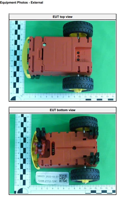
Click to zoom
Application Details
- Equipment Class
- DTS - Digital Transmission System
- Date of Grant
- Jan 25, 2023
- Application Purpose
- Original Equipment
- Date of Application
- Jan 25, 2023
- Equipment Note
- Early Coding
- Frequency Range
- 2402.00000000 - 2480.00000000
- Company
- fischertechnik GmbH
- Country
- Germany
Documents & Files
Document Text
Text extracted from the exhibit documents filed with the FCC. Open a document above to read the original.
Users Manual
EARLY CODING 1 Table of Contents Downloading the app and preparations ............................................................................................................ 2 Adventure 1: Connecting to the “First Coding” App / remote control .............................................................. 4 Adventure 3: Recording and saving motions ................................................................................................... 10 Adventure 4: Programming using programming blocks and traveling along a path ...................................... 13 Adventure 5: Trying out sensors ...................................................................................................................... 17 Adventure 6: Following a track ........................................................................................................................ 20 Adventure 7: Detecting an obstacle on the track and turning around ........................................................... 21 Adventure 8: Following a track – detecting an obstacle – playing a sound .................................................... 23 Adventure 9: Robby is trapped ........................................................................................................................ 25 Adventure 10: Noise activation ....................................................................................................................... 29 Adventure 11: The wanderer ........................................................................................................................... 31 What’s next? .................................................................................................................................................... 35 2 Downloading the app and preparations • First, download the “First Coding App” from the Google Play store (Android) or App store (Apple) for your smartphone or tablet. • Open the battery compartment of the Robby and place batteries in the compartment. • Switch on your Robby and make sure the LED is illuminated green. 3 • Now, assemble your Robby. Select one of the three available models and build it using the building instructions. 4 Adventure 1: Connecting to the “First Coding” App / remote control • Open the app on your smartphone or table. • After you have opened the app, click the Bluetooth symbol which is highlighted blue. • Press the left button on the Robby until the LED starts flashing green. 5 • After the connection is completed successfully, your app interface should appear as follows. Use the track ball at the bottom right side of the display to steer your Robby. 6 Adventure 2: Getting started programming • We’re going to get started by programming something easy, let's go! • The goal is for your Robby to play a sound when the bumper is touched. • We will use the following block to do so - drag it to the programming interface, this is our query for the bumper: 7 To delete a block, you can simply drag it to the trash can: • After you have inserted the block for the bumper query, it is time to switch functions. To do so, simply click the circular arrow: • After you click it, the function of the blocks will change. 8 • Now, select the sound block and add it to the programming interface, to the right of your green block: • Click the block once again to select a certain sound. 9 • Now, test out your program. To do so, click the “Play” button highlighted in green: • Try out your program by pressing the bumper on your Robby. This sound will now be played each time an obstacle touches the bumper of your Robby. 10 Play Record Adventure 3: Recording and saving motions • Make your Robby travel in any pattern you like. You will see that it remembers the pattern, and you can travel the programmed path as often as you like. • You can find these options using the track ball: 11 Stop • Use “Record” to start the learning phase. Your Robby will now remember each motion you carry out after you press Record. After you have traveled a specific path, for instance, you can press “Stop.” • Now, move your Robby back to its initial position and click “Play”: • The Robby will now copy exactly the movements that you made during the recording. This is a very simple way to program the Robby. In technical language, this is referred to as “teach-in programming.” 12 • The program will be retained until you either switch off the Robby or end the coding app. • If you would like to carry out additional tests, simply make your Robby travel in a square and see how well it can remember the path. 13 Adventure 4: Programming using programming blocks and traveling along a path • Next, we will use programming blocks to make the Robby travel along a certain path. • Task: Make the Robby travel forward for 20cm o Make the Robby travel forward for 20cm o To do so, you only need the following blocks: 14 o Press the blue block to set the distance: • Task: Make the Robby turn around and travel backward for 20cm o Now, try it out on your own. If you can’t figure out the task, see the next page for the solution 15 • Solution: • The grey blocks with a clock on them are delays. In this case, the Robby will wait for 1 second each time before executing the next block • So far so good, keep it up. You’re on the best path to becoming a great programmer. 16 • You can use the Save symbol at the top right to save the program on your smartphone or tablet and give it a name. 17 Adventure 5: Trying out sensors • Sensors are components the Robby uses to perceive its environment. It can use them to see or touch something. You are already familiar with the bumper. When you press it, there are 2 sensors inside the Robby that detect whether the bumper is pressed on the left, right or in the center. • The image at the top right of the screen shows you the point at which the bumper was pressed. Try it out. What do you observe? • Your Robby should now detect which side of the bumper was pressed. 18 • There ar…
Text truncated - open the document above for the full version.
Users Manual
Early Coding ROBOTICS 3 MODELS Bauanleitung Assembly instruction Instructions de montage Bouwhandleiding Instrucciónes de construcción Manual de montagem Istruzioni di montaggio Инструкция по сборке 安装说明书 Early Coding ROBOTICS fischertechnik GmbH Klaus-Fischer-Str. 1 72178 Waldachtal Germany Phone: +49 74 43/12-43 69 Fax: +49 74 43/12-45 91 [email protected] www.fischertechnik.de www.fischertechnik.de 185595 · 02/22 · Co · Printed in Germany · Technische Änderungen vorbehalten · Subject to technical modifications ■ ■ Software und spannende Abenteuer: Auf dem fischertechnik eLearning Portal findest du: • Installationshinweise zur First Coding App • Erste Schritte und weiterführende Informationen • Spannende Abenteuer für deine Roboter Link zum eLearning Portal: https://www.fischertechnik.de/elearning-earlycoding ■ ■ Software and exciting adventures: On the fischertechnik eLearning portal, you will find: • Installation information for the First Coding App • First steps and further information • Exciting adventures for your robots Link to the eLearning portal: https://www.fischertechnik.de/elearning-earlycoding ■■ Des logiciels et une aventure passionnante: Sur le portail de eLearning fischertechnik, vous trouverez: • Consignes d’installations pour l‘application First Coding • Premiers pas et autres informations • Des aventures passionnantes pour votre robot Lien vers le portail de eLearning: https://www.fischertechnik.de/elearning- earlycoding ■■ Software en spannende avonturen: Op het fischertechnik eLearning-portaal vindt je: • instructies voor de installatie van de First Coding-app • De eerste stappen en uitgebreide informatie • Spannende avonturen voor jouw robots Link naar het eLearning-portaal: https://www.fischertechnik.de/elearning- earlycoding ■■ Software y aventuras emocionantes: En el portal eLearning de fischertechnik encontrarás: • Instrucciones de instalación de la aplicación First Coding • Primeros pasos e información para avanzar • Emocionantes aventuras para tus robots Enlace al portal eLearning: https://www.fischertechnik.de/elearning- earlycoding ■■ Software e aventuras emocionantes: No portal de aprendizagem virtual da fischertechnik, você encontra: • Instruções de instalação para o App First Coding • Primeiros passos e informações de instrução adicionais • Aventuras emocionantes para seus robôs Link para o portal de aprendizagem virtual: https://www.fischertechnik.de/elearning- earlycoding ■■ Software e avventure entusiasmanti: Sul portale di eLearning di fischertechnik puoi trovare: • Istruzioni di installazione della First Coding App • Primi passi e ulteriori informazioni • Avventure entusiasmanti per i tuoi robot Link al portale di e-learning: https://www.fischertechnik.de/elearning- earlycoding ■■ Программы и захватывающие приключения: на обучающем интернет-портале fi schertechnik ты найдешь: • Инструкции по установке приложения First Coding • Первые шаги и подробную информацию • Захватывающие приключения для твоих роботов Ссылка на обучающий интернет-портал: https://www.fischertechnik.de/elearning-earlycoding ■■ 软件和激动人心的奇妙之旅: 在 fi schertechnik eLearning 在线学习门户网站上,您可以发现: • First Coding 应用程序的安装提示 • 前几个步骤和进一步的信息 • 利用您的机器人开启激动人心的奇妙之旅 eLearning 在线学习门户网站的链接: https://www.fischertechnik.de/elearning-earlycoding earlycoding 1 6 22 43 6 Bob LillyGary 2 31 010 4 x 31 124 3 x 31 913 2 x 31 981 4 x 31 983 2 x 32 064 1 x 32 085 1 x 32 627 2 x 32 913 2 x 34 995 2 x 35 049 2 x 35 404 1 x 36 573 1 x 37 237 3 x 37 238 1 x 37 468 2 x 38 241 1 x 38 428 1 x 38 464 1 x 116 252 2 x 154 452 2 x 161 691 2 x 163 200 2 x 163 201 3 x 163 204 4 x 172 809 2 x 183 268 1 x Art.-Nr. 189521 189 521 1 x ROBOTICS 189728 · 02/22 · Co · Printed in Germany · Technische Änderungen vorbehalten · Subject to technical modifications 189 728 1 x Einzelteilübersicht Onderdelenoverzicht Singoli componenti Spare parts list Lista da piezas Перечень деталей Liste des pièces détachées Resumo de peça individual 零件概览 Montagetipps Montagetips Consigli per il montaggio Tips for assembly Consejos para el montaje Советы по сборке Tuyaux pour le montage ”Dicas” para montagem 装配建议 3x AAA Tips for assembly Consejos para el montaje Tuyaux pour le montage ”Dicas” para montagem Montagetipps Montagetips Consigli per il montaggio Советы по сборке 装配建议 3x AAA Batterien sind nicht Inhalt der Packung Batteries not included Batteries non comprise De batterijen wordt niet meegeleverd La baterias no está incluida en el suministro A baterias não é o conteúdo da embalagem La batteria non è inclusa nella confezione Батарея в комплект не входит 包装中不含电池 3 ■■Nicht wiederaufladbare Batterien dürfen nicht geladen werden · Aufladbare Batterien dürfen nur von Erwachsenen geladen werden · Aufladbare Batterien sind aus dem Batteriehalter herauszunehmen, bevor sie geladen werden. · Batterien müssen mit der richtigen Polarität eingelegt werden. · Leere Batterien müssen aus dem Spielzeug herausgenommen werden · Die Anschlussklemmen dürfen nicht kurzgeschlossen werden. · Verbrauchte Batterien dem Sondermüll zuführen. · Drähte nicht in Steckdose einführen! · Ungleiche Batterietypen oder neue und gebrauchte Batterien dürfen nicht zusammen verwendet werden. ■■Do not attempt to charge NON-rechargeable batteries. · Rechargeable batteries are only to be charged by adults. · Take rechargeable batteries out of the battery tray before charging them. · Insert batteries with the correct polarity. · Remove dead batteries from the toy. · Do not short circuit the connecting terminals! · Discard spent dry cells at special waste disposal centre. · Do not insert the wires into an outlet! · Do not use dissimilar battery types or new and used batteries together. ■■Il est interdit de recharger des piles qui ne sont pas des accumulateurs · Le chargement des accumulateurs doit toujours se faire par des adultes · Retirer les accumulateurs du support de pile avant de les recharger. · Veiller à la polarité correcte lors de la mise en place des piles. · Retirer impérati…
Text truncated - open the document above for the full version.
Cover Letter(s)
https://www.lairdconnect.com/ 1 © Copyright 2022 Laird Connectivity All Rights Reserved Americas: +1-800-492-2320 Europe: +44-1628-858-940 Hong Kong: +852-2762-4823 Regulatory Information v1.3 The BL651 holds current certifications in the following countries: Country/Region Regulatory ID USA (FCC) SQGBL651 EU N/A Canada (ISED) 3147A-BL651 UK (UKCA) N/A Japan (MIC) 201-180356 Australia N/A New Zealand N/A The BL651 family has been designed to operate with the antennas listed below with a maximum gain of 2 dBi. The required antenna impedance is 50 ohms. The OEM can choose a different manufacturer’s antenna but must make sure it is of same type and that the gain is less than or equal to the antenna that is approved for use.* *Note: Japan (MIC) lists applicable antennas on its certificates. If your antenna is not on the approved list, regardless of whether it is comparative, it must be added to the certificate before it can be used in Japan. Manufacturer Model Laird Connectivity Part Number Type Connector Peak Gain 2400-2480 MHz 2400-2500 MHz Laird Connectivity NanoBlue EBL2400A1-10MH4L PCB Dipole IPEX MHF4 2 dBi Laird Connectivity FlexPIFA 001-0022 PCB Dipole IPEX MHF4 2 dBi Mag.Layers EDA-8709-2G4C1-B27-CY 0600-00057 Dipole IPEX MHF4 2 dBi Laird Connectivity mFlexPIFA EFA2400A3S- 10MH4L PIFA IPEX MHF4 2 dBI Laird Connectivity 453-00005 PCB printed antenna NA Printed PCB N/A 0 dBi To ensure regulatory compliance, when integrating the BL651 into a host device, it is necessary to meet the documentation requirements set forth by the applicable regulatory agencies. The following sections (FCC, ISED Canada, European Union, https://www.lairdconnect.com/ 2 © Copyright 2022 Laird Connectivity All Rights Reserved Americas: +1-800-492-2320 Europe: +44-1628-858-940 Hong Kong: +852-2762-4823 and others) outline the information that may be included in the user’s guide and external labels for the host devices into which the BL651 is integrated. Model US/FCC 453-00005 452-00006 SQGBL651 The BL651 Series hold full modular approvals. The OEM must follow the regulatory guidelines and warnings listed below to inherit the modular approval. Part # Form Factor Tx Outputs Antenna 453-00005 Surface Mount 4 dBm PCB Trace 453-00006 Surface Mount 4 dBm IPEX MHF4 *Last two slots "XX" in Part # are used for production firmware release changes. Can be values 01-99, aa-zz The BL651 family has been designed to operate with the antennas listed below with a maximum gain of 2 dBi. The required antenna impedance is 50 ohms. Manufacturer Model Laird Connectivity Part Number Type Connector Peak Gain 2400-2480 MHz 2400-2500 MHz Laird Connectivity NanoBlue EBL2400A1-10MH4L PCB Dipole IPEX MHF4 2 dBi Laird Connectivity FlexPIFA 001-0022 PCB Dipole IPEX MHF4 2 dBi Mag.Layers EDA-8709-2G4C1-B27-CY 0600-00057 Dipole IPEX MHF4 2 dBi Laird Connectivity mFlexPIFA EFA2400A3S- 10MH4L PIFA IPEX MHF4 2 dBI Laird Connectivity 453-00005 PCB printed antenna NA Printed PCB N/A 0 dBi This equipment has been tested and found to comply with the limits for a Class B digital device, pursuant to Part 15 of the FCC Rules. These limits are designed to provide reasonable protection against harmful interference in a residential installation. This equipment generates, uses, and can radiate radio frequency energy and, if not installed and used in accordance with the instructions, may cause harmful interference to radio communications. However, there is no guarantee that interference will not occur in an installation. If this equipment does cause harmful interference to radio or television reception, which can be determined by turning the equipment off and on, the user is encouraged to try to correct the interference by one of the following measures: ▪ Reorient or relocate the receiving antenna. ▪ Increase the separation between the equipment and receiver. ▪ Connect the equipment into an outlet on a circuit different from that to which the receiver is connected. ▪ Consult the dealer or an experienced radio/TV technician for help. FCC Caution: Any changes or modifications not expressly approved by the party responsible for compliance could void the user's authority to operate this equipment. https://www.lairdconnect.com/ 3 © Copyright 2022 Laird Connectivity All Rights Reserved Americas: +1-800-492-2320 Europe: +44-1628-858-940 Hong Kong: +852-2762-4823 This device complies with Part 15 of the FCC Rules. Operation is subject to the following two conditions: 1. This device may not cause harmful interference; and 2. This device must accept any interference received, including interference that may cause undesired operation. This product complies with the US portable RF exposure limit set forth for an uncontrolled environment and is safe for intended operation as described in this manual. Further RF exposure reduction can be achieved if the product is kept as far as possible from the user body or is set to a lower output power if such function is available. This transmitter must not be co-located or operated in conjunction with any other antenna or transmitter. This device is intended only for OEM integrators under the following condition: 1. The transmitter module may not be co-located with any other transmitter or antenna, If the condition above is met, further transmitter testing is not required. However, the OEM integrator is still responsible for testing their end-product for any additional compliance requirements required with this installed module. IMPORTANT NOTE: If this condition cannot be met (for example, certain laptop configurations or co-location with another transmitter), then the FCC authorization is no longer considered valid and the FCC ID cannot be used on the final product. In these circumstances, the OEM integrator is responsible for re-evaluating the end product (including the transmitter) and obtaining a separate FCC authorization. The end product must be labeled in a visible area with the following: Contains FCC ID: SQGBL651 The OEM inte…
Text truncated - open the document above for the full version.
Cover Letter(s)
Report No.: FR852803AE Page : 1 of 59 Report Version: Rev. 01 FCC Test Report FCC ID : SQGBL651 Equipment : Bluetooth 5.0 Module w/Integrated PCB Antenna (Refer to item 1.1.1 for more details) Model No. : BL651 Brand Name : Laird Applicant : Laird Technologies Address : W66N220 Commerce Court, Cedarburg, Wisconsin 53012, USA Standard : 47 CFR FCC Part 15.247 Received Date : May 28, 2018 Tested Date : Jun. 01 ~ Jun. 06, 2018 We, International Certification Corp., would like to declare that the tested sample has been evaluated and in compliance with the requirement of the above standards. The test results contained in this report refer exclusively to the product. It may be duplicated completely for legal use with the approval of the applicant. It shall not be reproduced except in full without the written approval of our laboratory. Reviewed by: Approved by: Along Chen / Assistant Manager Gary Chang / Manager Report No.: FR852803AE Page : 2 of 59 Report Version: Rev. 01 Table of Contents 1 GENERAL DESCRIPTION .................................................................................................................... 5 1.1 Information .............................................................................................................................................. 5 1.2 Local Support Equipment List ................................................................................................................ 7 1.3 Test Setup Chart .................................................................................................................................... 7 1.4 Test Equipment List and Calibration Data .............................................................................................. 8 1.5 Test Standards ....................................................................................................................................... 9 1.6 Measurement Uncertainty ...................................................................................................................... 9 2 TEST CONFIGURATION ..................................................................................................................... 10 2.1 Testing Condition ................................................................................................................................. 10 2.2 The Worst Test Modes and Channel Details ....................................................................................... 10 3 TRANSMITTER TEST RESULTS ........................................................................................................ 11 3.1 Conducted Emissions ........................................................................................................................... 11 3.2 6dB and Occupied Bandwidth .............................................................................................................. 16 3.3 RF Output Power .................................................................................................................................. 20 3.4 Power Spectral Density ........................................................................................................................ 22 3.5 Emissions in Restricted Frequency Bands ........................................................................................... 26 3.6 Emissions in non-restricted Frequency Bands ..................................................................................... 55 4 TEST LABORATORY INFORMATION ............................................................................................... 59 Report No.: FR852803AE Page : 3 of 59 Report Version: Rev. 01 Release Record Report No. Version Description Issued Date FR852803AE Rev. 01 Initial issue Aug. 22, 2018 Report No.: FR852803AE Page : 4 of 59 Report Version: Rev. 01 Summary of Test Results FCC Rules Test Items Measured Result 15.207 AC Power Line Conducted Emissions [dBuV]: 0.369MHz 34.13 (Margin -14.39dB) - AV Pass 15.247(d) 15.209 Radiated Emissions Meet the requirement of limit Pass 15.247(b)(3) Maximum Output Power Power [dBm]: 4.93 Pass 15.247(a)(2) 6dB Bandwidth Meet the requirement of limit Pass 15.247(e) Power Spectral Density Meet the requirement of limit Pass 15.203 Antenna Requirement Meet the requirement of limit Pass Report No.: FR852803AE Page : 5 of 59 Report Version: Rev. 01 1 General Description 1.1 Information 1.1.1 Product Details The following models are provided to this EUT. Brand Name Model Name Product Name Description Laird BL651 Bluetooth 5.0 Module w/Integrated PCB Antenna Printed PCB Antenna Bluetooth 5.0 Module w/External Antenna MHF4 Connector Type Antenna 1.1.2 Specification of the Equipment under Test (EUT) RF General Information Frequency Range (MHz) Bluetooth Mode Ch. Freq. (MHz) Channel Number Data Rate 2400-2483.5 V5.0 LE 2402-2480 0-39 [40] 1 Mbps 2400-2483.5 V5.0 LE 2402-2480 0-39 [40] 2 Mbps Note 1: Bluetooth LE (Low energy) uses GFSK modulation. 1.1.3 Antenna Details Ant. No. Manufacturer Model Laird Part Number Type Connector Gain (dBi) Remarks 1 Laird NanoBlue EBL2400A1- 10MH4L PCB Dipole IPEX MHF4 2 MHF4 Connector Type Antenna 2 Laird FlexPIFA 001-0022 PIFA IPEX MHF4 2 MHF4 Connector Type Antenna 3 Mag.Layers EDA-8709- 2G4C1-B27-CY 0600-00057 Dipole IPEX MHF4 2 MHF4 Connector Type Antenna 4 Laird mFlexPIFA EFA2400A3S- 10MH4L PIFA IPEX MHF4 2 MHF4 Connector Type Antenna 5 Laird PCB printed antenna NA Printed PCB N/A 0 Printed PCB Antenna Note: Antenna 3 was chosen for final rest 1.1.4 Power Supply Type of Equipment under Test (EUT) Power Supply Type DC 1.8V & DC 3.3V from host Report No.: FR852803AE Page : 6 of 59 Report Version: Rev. 01 1.1.5 Accessories N/A 1.1.6 Channel List Frequency band (MHz) 2400~2483.5 Channel Frequency (MHz) Channel Frequency (MHz) Channel Frequency (MHz) Channel Frequency (MHz) 37 2402 9 2422 18 2442 28 2462 0 2404 10 2424 19 2444 29 2464 1 2406 38 2426 20 2446 30 2466 2 2408 11 2428 21 2448 31 2468 3…
Text truncated - open the document above for the full version.
Cover Letter(s)
TCB GRANT OF EQUIPMENT AUTHORIZATION TCB Certification Issued Under the Authority of the Federal Communications Commission By: Telefication B.V. Edisonstraat 12a Zevenaar, NL-6902 PK Netherlands Date of Grant: 08/29/2018 Application Dated: 08/28/2018 Laird Technologies W66N220 Commerce Court Cedarburg, WI 53012 Attention: Thomas Smith , Director of EMC Compliance, Connectivity Solutio NOT TRANSFERABLE EQUIPMENT AUTHORIZATION is hereby issued to the named GRANTEE, and is VALID ONLY for the equipment identified hereon for use under the Commission's Rules and Regulations listed below. FCC IDENTIFIER: SQGBL651 Name of Grantee: Laird Technologies Equipment Class:Digital Transmission System Notes:Bluetooth 5.0 Module w/Integrated PCB Antenna / Bluetooth 5.0 Module w/External Antenna Modular Type:Single Modular Grant Notes FCC Rule Parts Frequency Range (MHZ) Output Watts Frequency Tolerance Emission Designator 15C2402.0 - 2480.0 0.003 Output power listed is conducted. This grant is valid only when the module is sold to OEM integrators and must be installed by the OEM or OEM integrators. The antennas used for this transmitter must not be co-located or operating in conjunction with any other antenna or transmitter. End-users may not be provided with the module installation instructions. OEM integrators and end-users must be provided with transmitter operating conditions for satisfying RF exposure compliance. Page 1 of 1FCC -OET TCB Form 731 Grant of Equipment Authorization 30-08-2018https://apps.fcc.gov/oetcf/tcb/reports/Tcb731GrantForm.cfm?RequestTimeOut=300
External Photos
FCC ID 2AFD4-183268 G0M-2112-1241 FCC ID 2AFD4-183268 G0M-2112-1241 FCC ID 2AFD4-183268 G0M-2112-1241 FCC ID 2AFD4-183268 G0M-2112-1241 FCC ID 2AFD4-183268 G0M-2112-1241 FCC ID 2AFD4-183268 G0M-2112-1241
Internal Photos
FCC ID 2AFD4-183268 G0M-2112-1241 FCC ID 2AFD4-183268 G0M-2112-1241 FCC ID 2AFD4-183268 G0M-2112-1241 FCC ID 2AFD4-183268 G0M-2112-1241 FCC ID 2AFD4-183268 G0M-2112-1241
RF Exposure Info
Test Report No.: G0M-2112-1241-TFC093PE-V01 Eurofins Product Service GmbH Storkower Str. 38c, D-15526 Reichenwalde, Germany Page 1 of 14 RF-EXPOSURE REPORT FCC 47 CFR Part 2.1093 RF-Exposure evaluation of portable equipment Report Reference No G0M-2112-1241-TFC093PE-V01 Testing Laboratory Eurofins Product Service GmbH Address Storkower Str. 38c 15526 Reichenwalde Germany Accreditation A2LA Accredited Testing Laboratory, Certificate No.: 1983.01 FCC Test Firm Designation Number: DE0008 ISED Testing Laboratory site: 3470A-2 Applicant fischertechnik GmbH Address Klaus-Fischer-Str. 1 72178 Waldachtal Germany Test Specification According to FCC rules Standard FCC 47 CFR 2.1093 Non-Standard Test Method None Equipment under Test (EUT): Product Description Roboter Chassis Early Coding for Toy and Education market Model(s) Roboter Chassis 183268 Additional Model(s) None Brand Name(s) fischertechnik Hardware Version(s) PL-221c Software Version(s) 0.20 FCC ID 2AFD4-183268 Test Result PASSED Test Report No.: G0M-2112-1241-TFC093PE-V01 Eurofins Product Service GmbH Storkower Str. 38c, D-15526 Reichenwalde, Germany Page 3 of 14 VERSION HISTORY Version History Version Issue Date Remarks Revised By 01 2022-10-12 Initial Release Test Report No.: G0M-2112-1241-TFC093PE-V01 Eurofins Product Service GmbH Storkower Str. 38c, D-15526 Reichenwalde, Germany Page 4 of 14 ABBREVIATIONS AND ACRONYMS Acronyms Acronym Description EIRP Equivalent Isotropic Radiated Power ERP Effective Radiated Power EUT Equipment Under Test LPE Low Power Exclusion Test Report No.: G0M-2112-1241-TFC093PE-V01 Eurofins Product Service GmbH Storkower Str. 38c, D-15526 Reichenwalde, Germany Page 5 of 14 REPORT INDEX 1 Equipment (Test Item) Under Test................................................................................................... 6 1.1 Reference Documents ................................................................................................................................... 7 1.2 Standalone radiation sources ........................................................................................................................ 8 1.3 Concurrent Sources ...................................................................................................................................... 8 2 Result Summary ................................................................................................................................. 9 3 RF-Exposure classification ............................................................................................................ 10 4 RF-Exposure limits and exclusion thresholds ............................................................................ 11 4.1 SAR limits .................................................................................................................................................... 11 4.2 SAR standalone test exclusion threshold .................................................................................................... 11 4.3 SAR concurrent test exclusion threshold ..................................................................................................... 12 5 RF-Exposure Evaluation ................................................................................................................. 13 6 Single Source Evaluation Results - FCC ...................................................................................... 14 Test Report No.: G0M-2112-1241-TFC093PE-V01 Eurofins Product Service GmbH Storkower Str. 38c, D-15526 Reichenwalde, Germany Page 6 of 14 1 Equipment (Test Item) Under Test Description Roboter Chassis Early Coding for Toy and Education market Model Roboter Chassis 183268 Additional Model(s) None Brand Name(s) fischertechnik Serial Number(s) 183268 Hardware Version(s) PL-221c Software Version(s) 0.20 FCC ID 2AFD4-183268 Equipment type End Product Environment General public Use case Body worn Test Report No.: G0M-2112-1241-TFC093PE-V01 Eurofins Product Service GmbH Storkower Str. 38c, D-155…
Text truncated - open the document above for the full version.
Contact Information
Applicant
Hartmut Knecht
Test Firm
Eurofins Product Service GmbHMichael Howard
Technical Specifications
| # | Rule Parts | Frequency Range | Power Output |
|---|---|---|---|
| 1 | 15C | 2.40 GHz - 2.48 GHz | 3.00 mW |