2AFG8SNWDG001Wireless USB Dongle
Cyber Power Systems, Inc.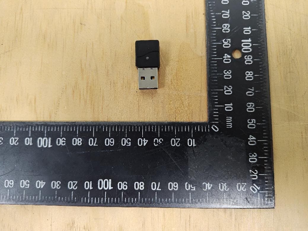
Click to zoom
Application Details
- Equipment Class
- DTS - Digital Transmission System
- Date of Grant
- Mar 19, 2026
- Application Purpose
- Original Equipment
- Equipment Note
- Wireless USB Dongle
- Frequency Range
- 2405.00000000 - 2475.00000000
- Company
- Cyber Power Systems, Inc.
- Country
- Taiwan
Documents & Files
Document Text
Text extracted from the exhibit documents filed with the FCC. Open a document above to read the original.
Users Manual
CyberPower Wireless ENVIRONMENTAL SENSOR/DONGLE EMWS-U01/EMWD-U01 Quick Start Guide Package Content EMWS-U01 EMWS-U01 (Wireless Sensor) ×1 Metal Plate ×1 Double-sided Adhesive ×1 Flat Head Screw ×1 Plastic Expansion Anchor ×1 Cable Tie ×2 Overview The wireless environmental sensor (EMWS-U01) along with wireless USB dongle (EMWD-U01) provide most Switched and Monitored PDUs to monitor the temperature and humidity of a server closet and/or data center in a wireless way. Users can establish thresholds that will automatically notify users when an event has occurred via email, SMS, SNMP traps and Syslog. EMWD-U01 EMWD-U01 (Wireless Dongle) x1 Serial number sticker x1 EMWS-U01 Battery CR2477 Battery Life 3–5 years Typical Measurement Range and Accuracy Temperature -4°F to 131°F with accuracy ± 0.9°F -20°C to 55°C with accuracy ± 0.5°C Humidity 10-90 RH with accuracy ± 2% Communication Wireless Radio Frequency Radio Band 2.4 GHz Physical Dimensions (L x W x H) 1.46 x 1.46 x 0.79 inches/ 37 x 37 x 20 mm Weight TBC. Safety Approvals FCC Class A, CE EMWD-U01 Power Consumption 120 mW Communication Connection Port USB Type A (2.0) Wireless Radio Frequency Radio Band 2.4 GHz Physical Dimensions (L x W x H) 0.30 × 0.59 × 1.16 inches/ 7.6 x 15 x 29.4 mm Weight TBC. Safety Approvals FCC Class A, CE Installation Guide EMWS-U01 Method 1: Cable Tie Mounting Step 1. Position the sensor against the desired location on the rack or PDU. Step 2. Pass a cable tie through the mounting holes on the sensor and secure it around the rack post or PDU frame. Step 3. Tighten the cable tie to hold the sensor in place. Method 2: Magnet Mounting Step 1. Clean the metal surface on the rack or PDU where the sensor will be installed. Step 2. Place the sensor back directly against the metal surface. The built-in magnets will hold it in place. Step 3. Ensure the sensor is securely attached and oriented for accurate temperature measurement. NOTE: Avoid mounting on painted or uneven metal surfaces for best adhesion. Method 3: Hook and Loop Tape Mounting Step 1. Clean the surface on the rack or PDU where the sensor will be installed. Apply one side of the hook and loop tape to the sensor bottom and the other side to the installation surface. Step 2. Attach the sensor and hold for a few seconds to ensure proper adhesion. Method 4: Fixed Mounting Step 1. Drill a hole on the rack or mounting surface compatible with the included anchor and insert the anchor. Step 2. Insert and tighten the screw, leaving enough exposed to hang or attach the sensor. Step 3. Mount the sensor horizontally or vertically. EMWD-U01 Step 1: Insert the EMWD-U01 into a USB port on the PDU. Step 2: Ensure the dongle is securely connected and recognized by the PDU. The EMWD-U01 is compatible only with supported devices and is not supported on Windows systems. Manufacturer ensuring that the RF parameters of the device cannot be operated outside its authorization for operation Conformance Approvals FCC Statement This device complies with Part 15 of the FCC Rules. Operation is subject to the following two conditions: 1. This device may not cause harmful interference, and 2. This device must accept any interference received, including interference that may cause undesired operation. NOTE: This equipment has been tested and found to comply with the limits for a Class A digital device, pursuant to part 15 of the FCC Rules. These limits are designed to provide reasonable protection against harmful interference when the equipment is operated in a commercial environment. This equipment generates, uses, and can radiate radio frequency energy and, if not installed and used in accordance with the instruction manual, may cause harmful interference to radio communications. Operation of this equipment in a residential area is likely to cause harmful interference in which case the user will be required to correct the interference at his own expense. If this equipment does cause harmful interference to radio or television reception, which can be determined by turning the equipment off and on, the user is encouraged to try to correct the interference by one or more of the following measures: • Reorient or relocate the receiving antenna. • Increase the separation between the equipment and receiver. • Connect the equipment into an outlet on a circuit different from that to which the receiver is connected. • Consult the dealer or an experienced radio/TV technician for help. Note: This equipment has been tested and found to comply with the limits for a Class A digital device, pursuant to part 15 of the FCC Rules. These limits are designed to provide reasonable protection against harmful interference when the equipment is operated in a commercial environment. This equipment generates, uses, and can radiate radio frequency energy and, if not installed and used in accordance with the instruction manual, may cause harmful interference to radio communications. Operation of this equipment in a residential area is likely to cause harmful interference in which case the user will be required to correct the interference at his own expense. Warning: Changes or modifications not expressly approved by the party responsible for compliance could void the user’s authority to operate the equipment. FCC Radiation Exposure Statement This equipment complies with FCC RF radiation exposure limits set forth for an uncontrolled environment. This equipment should be installed and operated with a minimum distance of 20 centimeters between the radiator and your body. This transmitter must not be co-located or operating in conjunction with any other antenna or transmitter. The antennas used for this transmitter must be installed to provide a separation distance of at least 20 cm from all persons and must not be co-located or operating in conjunction with any other antenna or transmitter. Industry Canada Statement This device complies with Industry Canada licence-exempt RSS 247 standard. Operation is subject to t…
Text truncated - open the document above for the full version.
Users Manual
CyberPower Wireless ENVIRONMENTAL SENSOR/DONGLE SNWEV001/SNWDG001 Quick Start Guide Package Content SNWEV001 SNWEV001 (Wireless Sensor) ×1 Metal Plate ×1 Double-sided Adhesive ×1 Flat Head Screw ×1 Plastic Expansion Anchor ×1 Cable Tie ×2 Overview The CyberPower wireless environmental sensor (SNWEV001) along with wireless USB dongle (SNWDG001) provide most Switched and Monitored PDUs to monitor the temperature and humidity of a server closet and/or data center in a wireless way. Users can establish thresholds that will automatically notify users when an event has occurred via email, SMS, SNMP traps and Syslog. SNWDG001 SNWDG001 (Wireless Dongle) x1 Serial number sticker x1 SNWEV001 Battery CR2477 Battery Life 3–5 years Typical Measurement Range and Accuracy Temperature -4°F to 131°F with accuracy ± 0.9°F -20°C to 55°C with accuracy ± 0.5°C Humidity 10-90 RH with accuracy ± 2% Communication Wireless Radio Frequency Radio Band 2.4 GHz Physical Dimensions (L x W x H) 1.46 x 1.46 x 0.79 inches/ 37 x 37 x 20 mm Weight TBC. Safety Approvals FCC Class A, CE SNWDG001 Power Consumption 120 mW Communication Connection Port USB Type A (2.0) Wireless Radio Frequency Radio Band 2.4 GHz Physical Dimensions (L x W x H) 0.30 × 0.59 × 1.16 inches/ 7.6 x 15 x 29.4 mm Weight TBC. Safety Approvals FCC Class A, CE Installation Guide SNWEV001 Method 1: Cable Tie Mounting Step 1. Position the sensor against the desired location on the rack or PDU. Step 2. Pass a cable tie through the mounting holes on the sensor and secure it around the rack post or PDU frame. Step 3. Tighten the cable tie to hold the sensor in place. Method 2: Magnet Mounting Step 1. Clean the metal surface on the rack or PDU where the sensor will be installed. Step 2. Place the sensor back directly against the metal surface. The built-in magnets will hold it in place. Step 3. Ensure the sensor is securely attached and oriented for accurate temperature measurement. NOTE: Avoid mounting on painted or uneven metal surfaces for best adhesion. Method 3: Hook and Loop Tape Mounting Step 1. Clean the surface on the rack or PDU where the sensor will be installed. Apply one side of the hook and loop tape to the sensor bottom and the other side to the installation surface. Step 2. Attach the sensor and hold for a few seconds to ensure proper adhesion. Method 4: Fixed Mounting Step 1. Drill a hole on the rack or mounting surface compatible with the included anchor and insert the anchor. Step 2. Insert and tighten the screw, leaving enough exposed to hang or attach the sensor. Step 3. Mount the sensor horizontally or vertically. SNWDG001 Step 1: Insert the SNWDG001 into a USB port on the PDU. Step 2: Ensure the dongle is securely connected and recognized by the PDU. The SNWDG001 is compatible only with supported devices and is not supported on Windows systems. Manufacturer ensuring that the RF parameters of the device cannot be operated outside its authorization for operation. Conformance Approvals FCC Statement This device complies with Part 15 of the FCC Rules. Operation is subject to the following two conditions: 1. This device may not cause harmful interference, and 2. This device must accept any interference received, including interference that may cause undesired operation. NOTE: This equipment has been tested and found to comply with the limits for a Class A digital device, pursuant to part 15 of the FCC Rules. These limits are designed to provide reasonable protection against harmful interference when the equipment is operated in a commercial environment. This equipment generates, uses, and can radiate radio frequency energy and, if not installed and used in accordance with the instruction manual, may cause harmful interference to radio communications. Operation of this equipment in a residential area is likely to cause harmful interference in which case the user will be required to correct the interference at his own expense. If this equipment does cause harmful interference to radio or television reception, which can be determined by turning the equipment off and on, the user is encouraged to try to correct the interference by one or more of the following measures: • Reorient or relocate the receiving antenna. • Increase the separation between the equipment and receiver. • Connect the equipment into an outlet on a circuit different from that to which the receiver is connected. • Consult the dealer or an experienced radio/TV technician for help. Note: This equipment has been tested and found to comply with the limits for a Class A digital device, pursuant to part 15 of the FCC Rules. These limits are designed to provide reasonable protection against harmful interference when the equipment is operated in a commercial environment. This equipment generates, uses, and can radiate radio frequency energy and, if not installed and used in accordance with the instruction manual, may cause harmful interference to radio communications. Operation of this equipment in a residential area is likely to cause harmful interference in which case the user will be required to correct the interference at his own expense. Warning: Changes or modifications not expressly approved by the party responsible for compliance could void the user’s authority to operate the equipment. FCC Radiation Exposure Statement This equipment complies with FCC RF radiation exposure limits set forth for an uncontrolled environment. This equipment should be installed and operated with a minimum distance of 20 centimeters between the radiator and your body. This transmitter must not be co-located or operating in conjunction with any other antenna or transmitter. The antennas used for this transmitter must be installed to provide a separation distance of at least 20 cm from all persons and must not be co-located or operating in conjunction with any other antenna or transmitter. Industry Canada Statement This device complies with Industry Canada licence-exempt RSS 247 standard. Operation is …
Text truncated - open the document above for the full version.
External Photos
Appendix EP Photographs of EUT Product: Wireless USB Dongle Brand Name: Cyber Power Type Identification: SNWDG001, EMWD-U01 Page 1 of 3 Appendix EP Photographs of EUT Product: Wireless USB Dongle Brand Name: Cyber Power Type Identification: SNWDG001, EMWD-U01 Page 2 of 3 Appendix EP Photographs of EUT Product: Wireless USB Dongle Brand Name: Cyber Power Type Identification: SNWDG001, EMWD-U01 Page 3 of 3
ID Label/Location Info
2. l'utilisateur de l'appareil doit accepter tout brouillage radioélectrique subi, même si le brouillage est susceptible d'en compromettre le fonctionnement. Canadian Compliance Statement CAN ICES-3 (A)/NMB-3(A) Model: EMWS-U01 FCC ID: 2AFG8SNWEV001 IC: 11470A-SNWEV001 Model: EMWD-U01 FCC ID: 2AFG8SNWDG001 IC: 11470A-SNWDG001 已註解 [S1]: 新增FCC ID 跟IC ID/拿掉NCC警語 2. l'utilisateur de l'appareil doit accepter tout brouillage radioélectrique subi, même si le brouillage est susceptible d'en compromettre le fonctionnement. Canadian Compliance Statement CAN ICES-3 (A)/NMB-3(A) Model: SNWEV001 FCC ID: 2AFG8SNWEV001 IC: 11470A-SNWEV001 Model: SNWDG001 FCC ID: 2AFG8SNWDG001 IC: 11470A-SNWDG001 NCC警語 取得審驗證明之低功率射頻器材,非經核准,公司、商號或使用者均不得擅自變更頻率、加大功率或變更原設計之 特性及功能。低功率射頻器材之使用不得影響飛航安全及干擾合法通信;經發現有干擾現象時,應立即停用,並改 善至無干擾時方得繼續使用。前述合法通信,指依電信管理法規定作業之無線電通信。低功率射頻器材須忍受合法 通信或工業、科學及醫療用電波輻射性電機設備之干擾。 本產品內含發射器模組
Internal Photos
Appendix EP Photographs of EUT Product: Wireless USB Dongle Brand Name: Cyber Power Type Identification: SNWDG001, EMWD-U01 Page 1 of 3 Appendix EP Photographs of EUT Product: Wireless USB Dongle Brand Name: Cyber Power Type Identification: SNWDG001, EMWD-U01 Page 2 of 3 Appendix EP Photographs of EUT Product: Wireless USB Dongle Brand Name: Cyber Power Type Identification: SNWDG001, EMWD-U01 Page 3 of 3 Antenna Location RF module, model: STM32WB55
RF Exposure Info
TÜ V SÜ D Asia Ltd., Taiwan Branch 7F., No. 37, Sec. 2, Zhongyang S. Rd., Beitou District, Taipei City, 11270, Taiwan (R.O.C.) Phone: + 886 2 2898-6818 Fax: + 886 2 2895-1598 Revision: 1.0 Effective: 2024-06-07 Page 1 of 6 RF Exposure Evaluation Applicant : Cyber Power Systems, Inc. Product : Wireless USB Dongle Model : SNWDG001, EMWD-U01 FCC ID : 2AFG8SNWDG001 In accordance with FCC rule Part §1.13101 RESPONSIBLE FOR NAME SIGNATURE DATE Approved By Jack Chang 2025.08.28 Prepared By Ariel Hsu 2025.08.28 Signatures in this approval box have checked this document in line with the requirements of TÜ V SÜ D Product Service control rules. EXECUTIVE SUMMARY TÜ V SÜ D Asia Ltd., reports apply only to the specific samples tested under stated test conditions. Construction of the actual test samples has been documented. It is the manufacturer's responsibility to assure that additional production units of this model are manufactured with identical electrical and mechanical components. The manufacturer/importer is responsible to the Competent Authorities for any modifications made to the production units which result in non-compliance to the relevant regulations. TÜ V SÜ D Asia Ltd. shall have no liability for any deductions, inferences or generalizations drawn by the client or others from TÜ V SÜD Asia Ltd. issued reports. This report is the confidential property of the client. As a mutual protection to our clients, the public and ourselves, extracts from the test report shall not be reproduced except in full without our written approval. Page 2 of 6 Contents 1 General Information ....................................................................................................................3 1.1 Report Modification Record ...........................................................................................................3 1.2 Introduction ....................................................................................................................................3 1.3 Applied Standard ...........................................................................................................................4 1.4 Deviation from standards ..............................................................................................................4 1.5 Reference Test Report ..................................................................................................................4 2 General EUT Information ............................................................................................................5 2.1 Technical Specification of EUT .....................................................................................................5 2.2 Antenna List ..................................................................................................................................5 3 FCC Maximum Permissible Exposure Evaluation ...................................................................6 3.1 Introduction ....................................................................................................................................6 3.2 Reference Levels ..........................................................................................................................6 3.3 Power Density Calculation (Worst Case) ......................................................................................6 Page 3 of 6 1 General Information 1.1 Report Modification Record Alterations and additions to this report will be issued to the holders of each copy in the form of a complete document. History of this test report Issue Description of Change Date of Issue 1 Initial Issue 2025-08-28 1.2 Introduction The information contained in this report is intended to show verification of RF qualification approval. The testing requirements of the standards for the tests listed in Section 1.5. Applicant : Cyber Power Systems, Inc. Address : 11F, No. 26,, Jinzhuang Rd., Neihu Dist., Taipei, Taiwan Manufacturer : CyberPower (ShenZhen) System lnc. Brand Name : CyberPower Product Name : Wireless USB Dongle Model Number(s) : SNWDG001, EMWD-U01 Date of Receipt of EUT : 2025-07-10 Start of Test : 2025-07-15 Finish of Test : 2025-07-24 Test Laboratory : TÜ V SÜ D Asia Ltd., Taiwan Branch Address : 7F., No. 37, Sec. 2, Zhongyang S. Rd., Beitou District, Taipei City 11270, R.O.C. Taiwan Test Location : TÜ V SÜ D Asia Ltd., Taiwan Branch, Guishan Laboratory Address : No. 31, Dinghu Road, Guishan District, Taoyuan City, TAIWAN (R.O.C.) The test facility is accredited by TAF (member of ILAC), under number 2573 according to ISO/IEC 17025: 2017. FCC Designation Number No.: TW2573 Page 4 of 6 1.3 Applied Standard FCC rule Part §2.1091 FCC Part §1.1310 FCC KDB 447498 D04 Interim General RF Exposure Guidance v01 1.4 Deviation from standards None 1.5 Reference Test Report Test Lab TÜ V SÜ D Asia Ltd., Taiwan Branch Report Number 6128625041301 Page 5 of 6 2 General EUT Information All information in this chapter was provided by the applicant. 2.1 Technical Specification of EUT Items EUT information Operating Frequency 2402 ~ 2475 MHz Channel number 15 Maximum Output Power (dBm) Zigbee: 4.38dBm Operation Voltage 5Vdc Modulation O-QPSK Test Software Version STM32CubeMonitor-RF: Version 2.12.0 2.2 Antenna List Antenna Type Brand Model Connector Freq. (MHz) Peak Antenna Gain (dBi) Main Chip Antenna WALSIN MULTILAYER CERAMIC ANTENNA Permanently attached antenna 2400 - 2500 2.13 Page 6 of 6 3 FCC Maximum Permissible Exposure Evaluation 3.1 Introduction This Standard specifies requirements for, and provides guidance on, assessing compliance with the exposure limits of radiofrequency (RF) safety standards such as IEEE Std C95.1. This includes methodologies for making an assessment (by measurement or computation) of human exposure to ambient RF fields and induced body currents in the frequency range of 0 kHz to 300 GHz. This Standard may also be used as a guide for making low-level environmental exp…
Text truncated - open the document above for the full version.
Test Report
Approval sheet Page 1 of 10 ASC_RFANT3216120A1T_V07 Aug. 2021 RFANT Series – RoHS Compliance MULTILAYER CERAMIC ANTENNA Halogens Free Product 2400 ~ 2500 MHz Working Frequency P/N: RFANT3216120A1T *Contents in this sheet are subject to change without prior notice. Approval sheet Page 2 of 10 ASC_RFANT3216120A1T_V07 Aug. 2021 FRATURES 1. Surface Mounted Devices with a small dimension of 3.2 X 1.6 X 1.2 mm 3 meet future miniaturization trend. 2. LTCC process 3. High stability in Temperature / Humidity Change APPLICATIONS 1. 2400 ~ 2500 MHz Working Frequency 2. Bluetooth, Wireless, HomeRF CONSTRUCTION Top view DIMENSIONS Figure Symbol Dimension (mm) L 3.20 ± 0.20 W 1.60 ± 0.10 T 1.20 ± 0.10 A 0.25 ± 0.15 PIN Connection 1 Feeding 2 Identification Mark 3 Soldering terminal P1 P3 P2 Approval sheet Page 3 of 10 ASC_RFANT3216120A1T_V07 Aug. 2021 ELECTRICAL CHARACTERISTICS RFANT3216120A1T Specification Working Frequency Range 2450 ± 50 MHz Fc (GHz) 2.5 Gain (dBi) 2 (Typical) Matching component valve Series 1 2.7nH Series 2 - Power Capacity 3 W max Maximum Input Power 5 Watts for 5 minutes Polarization Linear Azimuth Beamwidth Omni-directional Moisture sensitivity levels MSL is LEVEL 1 (Refer to : IPC/JEDEC J-STD-020) HBM ESD Pass 1KV on all pins (Base on AEC-Q200-002) MM ESD Pass 200V (Base on EIA/JESD22-A115) Operating & Storage Condition (Component) Operation Temperature Range: -40°C ~ +85°C Storage Temperature Range: -40°C ~ +85°C Storage Condition before Soldering (Included packaging material) Storage Temperature Range: +5 ~ +40°C Humidity: 30 to 70% relative humidity * This frequency must be adjusted to 2.45GHz with matching circuit. Approval sheet Page 4 of 10 ASC_RFANT3216120A1T_V07 Aug. 2021 Ground Soldering Pad 50 Transmission Line Unit : mm 19.4 Empty Area 6x6 mm 50 Feed line 45mm 20mm Series 1 Series 2 Ground Soldering Pad 50 Transmission Line Unit : mm 19.4 Empty Area 6x6 mm 50 Feed line 45mm 20mm Series 1 Series 2 SOLDER LAND PATTERN DESIGN Figure 1.66 0.8 2.3 1.63 6 3.43 1.6 6 1.36 0.36 0.88 0.34 1.88 1.83 0.8 0.54 1.66 0.8 2.3 1.63 6 3.43 1.6 6 1.36 0.36 0.88 0.34 1.88 1.83 0.8 0.54 Approval sheet Page 5 of 10 ASC_RFANT3216120A1T_V07 Aug. 2021 Antenna on Test Board ( Thickness 1.2mm) Antenna S11 on Test Board 0.8mm 1.6 mm 19.4 mm Empty Area 6x6 mm 50 Feed line 1.66mm GROUND 0.8mm 1.6 mm 19.4 mm Empty Area 6x6 mm 50 Feed line 1.66mm GROUND 0.8mm 1.6 mm 19.4 mm Empty Area 6x6 mm 50 Feed line 1.66mm GROUND 0.8mm 1.6 mm 19.4 mm Empty Area 6x6 mm 50 Feed line 1.66mm GROUND A Approval sheet Page 6 of 10 ASC_RFANT3216120A1T_V07 Aug. 2021 RADIATION PATTERN Radiation Pattern and Gain were dependent on measurement board design. The specification of RFANT3216120A1T antenna was measured based on the PCB size and installation position as shown in the below figure Test Board Vertical Horizontal Y - Z Plane Average Gain= 0.859 dBi Peak Gain = 2.13dBi Average Gain = 0.62 dBi Peak Gain= -6.47dBi Average Gain=-11.86dBi X - Z Plane Average Gain= -1.804 dBi Peak Gain= -7.43 dBi Average Gain= -12.30dBi Peak Gain= 1.07 dBi Average Gain= -2.21 dBi X - Y Plane Average Gain= -2.365 dBi Peak Gain= -9.98 dBi Average Gain= -15.53dBi Peak Gain= 1.84 dBi Average Gain= -2.57 dBi GROUND X Y Z GROUND X Y Z X Y Z Approval sheet Page 7 of 10 ASC_RFANT3216120A1T_V07 Aug. 2021 RELIABILITY TEST Test item Test condition / Test method Specification Solderability JIS C 0050-4.6 JESD22-B102D *Solder bath temperature:235 5C *Immersion time:2 0.5 sec Solder:Sn3Ag0.5Cu for lead-free At least 95% of a surface of each terminal electrode must be covered by fresh solder. Resistance to soldering heat JIS C 0050-5.4 *Preheating temperature:120~150°C, 1 minute. *Solder temperature:2705C *Immersion time:101 sec Solder:Sn3Ag0.5Cu for lead-free Measurement to be made after keeping at room temperature for 242 hrs No mechanical damage. Electrical specification shall satisfy the descriptions in electrical characteristics under the operational temperature range within -40 ~ 85°C. Loss of metallization on the edges of each electrode shall not exceed 25%. Drop Test JIS C 0044 Customer’s specification. *Height:75 cm *Test Surface:Rigid surface of concrete or steel. *Times:6 surfaces for each units;2 times for each side. No mechanical damage. Electrical specification shall satisfy the descriptions in electrical characteristics under the operational temperature range within -40 ~ 85°C. Vibration JIS C 0040 *Frequency:10Hz~55Hz~10Hz(1min) *Total amplitude:1.5mm *Test times:6hrs.(Two hrs each in three mutually perpendicular directions) No mechanical damage. Electrical specification shall satisfy the descriptions in electrical characteristics under the operational temperature range within -40 ~ 85°C. Adhesive Strength of Termination JIS C 0051- 7.4.3 *Pressurizing force: 5N (LGA terminal series);5N(≦0603); 10N(>0603) *Test time:10±1 sec No remarkable damage or removal of the termination. Bending test JIS C 0051- 7.4.1 The middle part of substrate shall be pressurized by means of the pressurizing rod at a rate of about 1 mm/s per second until the deflection becomes 1mm/s and then pressure shall be maintained for 51 sec. Measurement to be made after keeping at room temperature for 242 hours No mechanical damage. Electrical specification shall satisfy the descriptions in electrical characteristics under the operational temperature range within -40 ~ 85°C. Approval sheet Page 8 of 10 ASC_RFANT3216120A1T_V07 Aug. 2021 Temperature cycle JIS C 0025 1. 303 minutes at -40C3C, 2. 10~15 minutes at room temperature, 3. 303 minutes at +85C3C, 4. 10~15 minutes at room temperature, Total 100 continuous cycles Measurement to be made after keeping at room temperature for 242 hrs No mechanical damage. Electrical specification shall satisfy the descriptions in electrical characteristics under the operational temperature range within -40 ~ 85°C. High temperature JIS C 0021 *Temperature:85C2C *Test duration:1000+24/-0 hours Measu…
Text truncated - open the document above for the full version.
Test Report
TÜ V SÜ D Asia Ltd., Taiwan Branch 7F., No. 37, Sec. 2, Zhongyang S. Rd., Beitou District, Taipei City, 11270, Taiwan (R.O.C.) Phone: + 886 2 2898-6818 Fax: + 886 2 2895-1598 Revision: 1.0 Effective: 2024-06-07 Page 1 of 58 RF Test Report Report Number : 6128625041301 Applicant : Cyber Power Systems, Inc. Product : Wireless USB Dongle Model : SNWDG001, EMWD-U01 FCC ID : 2AFG8SNWDG001 IC : 11470A-SNWDG001 In accordance with FCC rule Part §15.247 ISED RSS-247 ISED RSS-Gen RESPONSIBLE FOR NAME SIGNATURE DATE Approved By Jack Chang 2026.02.02 Prepared By Ariel Hsu 2026.02.02 Signatures in this approval box have checked this document in line with the requirements of TÜ V SÜ D Product Service control rules. EXECUTIVE SUMMARY TÜ V SÜ D Asia Ltd., reports apply only to the specific samples tested under stated test conditions. Construction of the actual test samples has been documented. It is the manufacturer's responsibility to assure that additional production units of this model are manufactured with identical electrical and mechanical components. The manufacturer/importer is responsible to the Competent Authorities for any modifications made to the production units which result in non-compliance to the relevant regulations. TÜ V SÜ D Asia Ltd. shall have no liability for any deductions, inferences or generalizations drawn by the client or others from TÜ V SÜD Asia Ltd. issued reports. This report is the confidential property of the client. As a mutual protection to our clients, the public and ourselves, extracts from the test report shall not be reproduced except in full without our written approval. Report Number: 6128625041301 Page 2 of 58 Contents 1 General Information ....................................................................................................................3 1.1 Report Modification Record ...........................................................................................................3 1.2 Introduction ....................................................................................................................................3 1.3 Applied Standard ...........................................................................................................................4 1.4 Deviation from standards ..............................................................................................................4 1.5 List of applied test(s) of the EUT ...................................................................................................4 2 General EUT Information ............................................................................................................5 2.1 Technical Specification of EUT .....................................................................................................5 2.2 Variation of family model(s) ...........................................................................................................6 2.3 Antenna List ..................................................................................................................................6 3 Configuration of Equipment .......................................................................................................7 3.1 Equipment used ............................................................................................................................7 3.2 Cable(s) used ................................................................................................................................7 3.3 System configuration .....................................................................................................................8 4 General Test Configurations ................................................................................................... 10 4.1 Operating channels and frequencies ......................................................................................... 10 4.2 Description of test mode ............................................................................................................ 11 4.3 Test Condition ............................................................................................................................ 12 5 Test Result .....................…
Text truncated - open the document above for the full version.
Contact Information
Applicant
Kevin Hsu(Safety Manager)
[email protected]Fax: 886-2-8792-9621
Technical Contact
Cyber Power Systems (USA), Inc.Jake Shevik
4241 12th Avenue East, Suite 400 · United States
Test Firm
TUV SUD Asia Ltd. Taiwan BranchMax Yao
[email protected]Fax: +886 2 2895 1598
Technical Specifications
| # | Rule Parts | Frequency Range | Power Output |
|---|---|---|---|
| 1 | 15C | 2.40 GHz - 2.48 GHz | 2.70 mW |