2AFH5TXR1Water protection system
Whiz Bang Technologies Inc.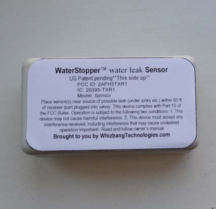
Click to zoom
Application Details
- Equipment Class
- DXX - Part 15 Low Power Communication Device Transmitter
- Date of Grant
- Aug 26, 2015
- Application Purpose
- Original Equipment
- Date of Application
- Aug 26, 2015
- Equipment Note
- Water protection system
- Frequency Range
- 2468.00000000 - 2468.00000000
- Company
- Whiz Bang Technologies Inc.
- Country
- Canada
Documents & Files
Document Text
Text extracted from the exhibit documents filed with the FCC. Open a document above to read the original.
Users Manual
______________________________________________________________________________________________________ Page 1 of 7 WaterStopper User Instruction Setup and Troubleshooting guide Thank you for purchasing the newest, most exciting development in home automation. WatersStopper is an affordable state of the art, purpose designed and built system that allows the user to easily reduce their risk of water damage caused by burst or leaky pipes inside a building. All water systems leak, it is just a matter of time. System description Water damage from burst or leaking pipes presents a major risk to landlords and home and business owners. Such losses add up to billions annually. While many such losses may be insurable, the inconvenience and stress associated with such disasters is stressful and unnecessary. The WaterStopper system consists of 5 water sensors which, when activated(by water), send a coded signal to the receiver. The receiver actuates a ball valve (included) which is installed in- line with the building’s main water line. This closes the valve and minimizes any further water damage. The receiver’s LED turns from green to red and the receiver emits an audible alarm tone. The receiver also sends a text (via Ethernet) if it has been plugged into a connected router with an Ethernet cable. This alerts the user of the water situation and allows them to take timely action. Precautions and limitations There are some important things to remember when setting up and using your new system 1) Like all low power radio devices it has a limited range. The sensors should not be located more than about 60 feet from the receiver. 2) A repeater unit can be installed between the sensor and the receiver to help increase the range. 3) The repeater is powered using a 3.3V DC adaptor (wall wart) with a smaller barrel jack. 4) The receiver is powered using a 5VDC AC adaptor (wall wart). It can also be powered using USB to barrel jack (cable supplied). If the receiver is not powered (indicated by a green LED) , the system will not function. 5) The ball valve must be installed correctly as described and illustrated below. The electrical cable must be plugged fully into the side of the receiver in order to actuate the ball valve and to allow the ball valve to be reset following a repair of a leak. ______________________________________________________________________________________________________ Page 2 of 7 Figure 1- Sensor Top side- coins for size comparison 6) Placement of sensors is important. The local microenvironment may require that the sensor is moved a few inches to allow its transmission to be received. 7) Sensors need to be located near a source of potential leaks, such as between a sink and a toilet, beside a hot water heater or near the floor drain in a basement. 8) Use of any unapproved parts or using the supplied parts in ways not described here could lead to unsatisfactory performance and loss of protection against water damage Figure 2- Electrical ball valve- prior to installation ______________________________________________________________________________________________________ Page 3 of 7 Regulatory warnings FCC/Industry Canada This device complies with FCC Part 15 and Industry Canada license exempt RSS standard(s). Operation is subject to the following two conditions: (1) this device may not cause interference, and (2) this device must accept any interference, including interference that may cause undesired operation of the device. This device complies with Health Canada’s Safety Code. The installer of this device should ensure that RF radiation is not emitted in excess of the Health Canada’s requirement. Changes or modifications not expressly approved by the party responsible for compliance could void the user’s authority to operate the equipment. Le présent appareil est conforme aux CNR d'Industrie Canada applicables aux appareils radio exempts de licence. L'exploitation est autorisée aux deux conditions suivantes : (1) l'appareil ne doit pas produire de brouillage, et (2) l'utilisateur de l'appareil doit accepter tout brouillage radioélectrique subi, même si le brouillage est susceptible d'en compromettre le fonctionnement Cet appareil est conforme avec Santé Canada Code de sécurité 6. Le programme d’installation de cet appareil doit s’assurer que les rayonnements RF n’est pas émis au-delà de I’exigence de Santé Canada. Les changements ou modifications non expressément approuvés par la partie responsable de la conformité pourraient annuler l'autorité de l'utilisateur à utiliser cet équipement. Setup and Installation Ensure that your Waterstopper system contains the following items: Wireless sensors (qnty 5)- see illustration 1 above Receiver module- (qnty 1)- see illustration Screws and tape to attach receiver to wall AC adaptor for receiver module (5VDC)- has 3.5 mm barrel jack (qnty 1) Ball valve assembly- has audio style 2.5mm jack (qnty1) Repeater (qnty 1) –small enclosure marked “Repeater” with one hole for 3.3VDC plug AC Adaptor for repeater (3.3VDC)- has smaller 2.5 mm barrel jack (qnty 1) Ethernet cable cat5 6 foot (qnty 1) Steps Un packaging and test 1) Plug the 5VDC power adaptor into the receiver- to the right of the red reset button 2) Plug the power adapter into a 120VAC receptacle 3) Plug the ball valve into the receiver ______________________________________________________________________________________________________ Page 4 of 7 4) Plug the Ethernet cable into the receiver and the other end into a router (LAN port) or repeater such as a Dlink DIR-505 Figure 3- Receiver- showing ball valve connection on left, red Ethernet cable on bottom left, red reset button in bottom middle and DC power supply on bottom right. Figure 4- Sensor metal pins up for testing (must be placed with pins down to operate) 5) Place a sensor (figure 4) -metal contact sides up- on a firm level surface. Wet two fingers of the other hand and touch (hold) both metal co…
Text truncated - open the document above for the full version.
Cover Letter(s)
Michael Cogill *[email protected] * 403-462-1857 July 27, 2015 Nemko Canada Inc. 303 River Road Ottawa, Ontario, Canada K1V 1H2 FCC ID: 2AFH5TXR1 Product Name: WaterStopper Request for Confidentiality Pursuant to Sections 0.457 and 0.459 of the commission’s rules, we hereby request that the following documents be held confidential: • Schematics • Block diagram • Bill of Materials These materials contain trade secrets and proprietary information and are not customarily released to the public. The public disclosure of this information might be harmful to the company and provide unjustified benefits to our competitors. Dated this 27 Day of July 20 15 By: Michael Cogill Signature Printed Title: Owner On behalf of : Whiz Bang Technologies Inc. Telephone: 4034621857 3
Cover Letter(s)
Michael Cogill- Owner [email protected] 403-462-1857 August 27, 2015 Nemko Canada Inc 303 River Road Ottawa K1V 1H2 Canada Differences between “sensor” and “repeater” models The sensor (figure 1 below) is a simple compact water sensor circuit that automatically turns on a radio transmitter (nRF24L01+) and sends a coded signal over a discrete frequency (2468 MHz) on the ISM band, when the contacts get wet. It is battery powered by 2x 2032 primary lithium batteries and is only on when the sensor is wet. Figure 1-Schematic drawing of Sensor Michael Cogill- Owner [email protected] 403-462-1857 The repeater (figure 2 below) is a simpler version of the exact same parts as the sensor. The two circuits have identical RF performance and RF components. The Repeater is a simpler (fewer parts- no switching or power regulation) version of the sensor. It is powered by an AC adaptor and remains in receive mode until it detects a transmission from a sensor. The device then switches to transmit mode to transmit an equivalent sensor signal to the receiver. The repeater demodulates the received signal and re-modulates the signal that it sends out. It does not remain in the send mode but returns to receive mode after a brief time period. Figure 2-Schematic drawing of Repeater Michael Cogill- Owner [email protected] 403-462-1857 Dated this 27th Day of August 20 15 By: Michael Cogill Signature Printed Title: Owner Telephone: 403-462-1857 Applicant: Whiz Bang Technologies Inc
ID Label/Location Info
WaterStopper™ water leak Sensor US Patent pending**This side up** FCC ID: 2AFH5TXR1 IC: 20395-TXR1 Model: Sensor Place sensor(s) near source of possible leak (under sinks etc.) within 60 ft of receiver (part plugged into valve) This device complies with Part 15 of the FCC Rules. Operation is subject to the following two conditions: 1. This device may not cause harmful interference. 2. This device must accept any interference received, including interference that may cause undesired operation Important!-.Read and follow owner’s manual Brought to you by WhizbangTechnologies.com WaterStopper™ water leak Repeater FCC ID: 2AFH5TXR1 IC: 20395-TXR1 Model: Repeater Place repeater in approximate center of building and within 60 ft of receiver (part plugged into valve). This unit uses a DC adapter This device complies with Part 15 of the FCC Rules. Operation is subject to the following two conditions: 1. This device may not cause harmful interference. 2. This device must accept any interference received, including interference that may cause undesired operation. Important!-Read and follow owner’s manual. US Patent Pending Brought to you by WhizbangTechnologies.com LABEL LOCATION
Internal Photos
Figure 1 Sensor Inside Top Figure 2 Sensor Inside Bottom Figure 1 Repeater Inside Top Figure 2 Repeater Inside Bottom
Operational Description
Operational description The device is a simple compact water sensor circuit that automatically turns on a radio transmitter (nRF24L01+) and sends a coded signal over a discrete frequency (2468 MHz) on the ISM band, when the contacts get wet. This allows a receiver to close the water main valve (there is an electrically actuated ball valve installed in series with the building’s manual shutoff valve), emit an audible tone, light a visual indicator and send a text message to the user. The receiver has a reset button that is depressed which allows the valve to be reopened and the system returns to its ready state. The device can also be programmed to act as a radio signal repeater for a nearby sensor. In that case, it is a simpler (fewer parts- no switching or power regulation) version of the sensor. It remains in receive mode until it detects a transmission from a sensor. The device then switches to transmit mode to transmit an equivalent sensor signal to the receiver. The repeater demodulates the received signal and re-modulates the signal that it sends out. It does not remain in the send mode but returns to receive mode after a brief time period.
Test Report
www.nemko.com Nemko Canada Inc., a testing laboratory, is accredited by the Standards Council of Canada. The tests included in this report are within the scope of this accreditation FCC 15.249 and RSS-210 A2.9.docx; Date: July 2015 SCC Accredited LAB LAB Accrédité CCN TM ONE WORLDOURAPPROVAL Test report 290906-1TRFWL Date of issue: August 24, 2015 Applicant: Whiz Bang Technologies Inc Product: WaterStopper TM Water Leak Sensor/Repeater Model: Model Variant: Sensor Repeater FCC ID: IC Registration number: 2AFH5TXR1 20395-TXR1 Specifications: FCC 47 CFR Part 15 Subpart C, §15.249 Operation in the 902–928 MHz, 2400–2483.5 MHz, 5725–5850 MHz and 24.0–24.25 GHz RSS-210, Issue 8, December 2010, Annex 2.9 Devices operating in 902–928, 2400–2483.5 and 5725–5875 MHz frequency bands for any application Report reference ID: 290906-1TRFWL Page 2 of 25 Test location Company name Nemko Canada Inc. Address 303 River Road City Ottawa Province Ontario Postal code K1V 1H2 Country Canada Telephone +1 613 737 9680 Facsimile +1 613 737 9691 Toll free +1 800 563 6336 Website www.nemko.com Site number FCC: 176392; IC: 2040A-4 (3 m semi anechoic chamber) Tested by Andrey Adelberg, Senior Wireless/EMC Specialist Reviewed by Kevin Rose, Wireless/EMC Specialist Review date August 24, 2015 Reviewer signature Limits of responsibility Note that the results contained in this report relate only to the items tested and were obtained in the period between the date of initial receipt of samples and the date of issue of the report. This test report has been completed in accordance with the requirements of ISO/IEC 17025. All results contain in this report are within Nemko Canada’s ISO/IEC 17025 accreditation. Copyright notification Nemko Canada Inc. authorizes the applicant to reproduce this report provided it is reproduced in its entirety and for use by the company’s employees only. Any use which a third party makes of this report, or any reliance on or decisions to be made based on it, are the responsibility of such third parties. Nemko Canada Inc. accepts no responsibility for damages, if any, suffered by any third party as a result of decisions made or actions based on this report. © Nemko Canada Inc. Report reference ID: 290906-1TRFWL Page 3 of 25 Table of contents Table of contents .......................................................................................................................................................................................................... 3 Section 1. Report summary ................................................................................................................................................................................. 4 1.1 Applicant and manufacturer .................................................................................................................................................................................... 4 1.2 Test specifications .................................................................................................................................................................................................... 4 1.3 Test methods ............................................................................................................................................................................................................ 4 1.4 Statement of compliance ......................................................................................................................................................................................... 4 1.5 Exclusions ................................................................................................................................................................................................................. 4 1.6 Test report revision history ...................................................................................................................................................................................... 4 Section 2. Summary of test results ....................................................................................................................................................................... 5 2.1 FCC Part 15 Subpart C, general requirements test results ........................................................................................................................................ 5 2.2 FCC Part 15 Subpart C, intentional radiators test results.......................................................................................................................................... 5 2.3 IC RSS-GEN, Issue 4, test results ............................................................................................................................................................................... 5 2.4 IC RSS-210, Issue 8, test results ................................................................................................................................................................................ 5 Section 3. Equipment under test (EUT) details ..................................................................................................................................................... 6 3.1 Sample information .................................................................................................................................................................................................. 6 3.2 EUT information ....................................................................................................................................................................................................... 6 3.3 Technical information .............................................................................................................................................................................................. 6 3.4 Product description and theory of operation ........................…
Text truncated - open the document above for the full version.
Test Setup Photos
www.nemko.com Nemko Canada Inc., a testing laboratory, is accredited by the Standards Council of Canada. The tests included in this report are within the scope of this accreditation setup photos.docx; Date: May 2013 SCC Accredited LAB LAB Accrédité CCN TM ONE WORLDOURAPPROVAL Setup photos 290906-1RADWL Date of issue: August 24, 2015 Applicant: Whiz Bang Technologies Inc Product: WaterStopper TM Water Leak Sensor/Repeater Model: Model: Sensor Sensor FCC ID: IC Registration number: 2AFH5TXR1 20395-TXR1 Section 1: setup photos Report reference ID: 290906-1RADWL Page 2 of 5 Section 1. Setup photos 1.1 Radiated emissions setup Section 1: setup photos Report reference ID: 290906-1RADWL Page 3 of 5 1.2 Radiated emissions setup Section 1: setup photos Report reference ID: 290906-1RADWL Page 4 of 5 1.3 Conducted emissions setup Section 1: setup photos Report reference ID: 290906-1RADWL Page 5 of 5 1.4 Conducted emissions setup
Contact Information
Applicant
Michael Cogill(Owner)
Test Firm
Nemko Canada Inc. (Ottawa)Charles Neal
Technical Specifications
| # | Rule Parts | Frequency Range | Power Output |
|---|---|---|---|
| 1 | 15C | 2.47 GHz - 2.47 GHz | - |