2AFZXSP-RBTSW-BKBluetooth shutter
Ningbo Fancier Photographic Equipment Co.,Ltd.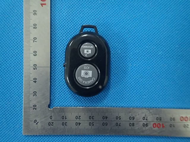
Click to zoom
Application Details
- Equipment Class
- DXX - Part 15 Low Power Communication Device Transmitter
- Date of Grant
- Sep 29, 2015
- Application Purpose
- Original Equipment
- Date of Application
- Sep 29, 2015
- Equipment Note
- Bluetooth shutter
- Frequency Range
- 2402.00000000 - 2480.00000000
- Country
- China
Documents & Files
Document Text
Text extracted from the exhibit documents filed with the FCC. Open a document above to read the original.
Users Manual
Specifications: Compatibility: Apple, Android Load capacity: 1.1 lbs. Weight: 6 oz. Maximum length: 35 in. Minimum length: 9.25 in. Leg sections: 5 Leg material: aluminum Maximum working distance: 30 feet Battery: CR2032 Warranty: 1 year Product design and specifications subject to change without notice. ToCAD America Inc. 53 Green Pond Road Rockaway, NJ 07866, USA sunpak.com How to use: 1. Loosen the Lock Knob and rotate the smartphone mount upwards to allow it to accept a smartphone or phablet. To lock the smartphone holder in place, tighten the Lock Knob. 2. Attach your smartphone or phablet in the adjustable holder. 3. Attach the Bluetooth Shutter Release by clipping it onto the SelfieStick section. Pair the Shutter Release with your smartphone or phablet. 4. To attach a GoPro to your SelfieStick, loosen and re- move the Lock Knob and remove the smartphone holder from the SelfieStick. Then attach a GoPro directly into the forks on the SelfieStick. Replace the Lock Knob and re-tighten to secure. 5. To attach a camera, camcorder or any other unit that has a standard 1/4”-20 mount, remove the Lock Knob and install the Point & Shoot adapter. Note: For additional information and pairing or mount- ing instructions, please see the reverse page. Adjustable Smartphone Mount can support practi- cally any smartphone or phablet. Strong and sturdy enough for any smartphone. Expands up to 3.5” wide. Lock Knob allows the smartphone holder to be adjusted to allow for 180° movement and settings. Loosen the lock knob to position your head and tighten it once you have achieved your desired position. Folds inward for compact storage. You can also remove the smartphone holder and mount a GoPro directly to the SelfieStick, or mount a point & shoot camera via the in- cluded 1/4”-20 mount. SelfieStick has five Twist and Lock Sections. To deploy the sections, grasp the foam grip in one hand and the smartphone holder in the other hand. Rotate the foam grip counter-clockwise. You will feel each section unlock with each slight rotation. Once all of the sections are unlocked, extend the SelfieStick to your desired length. Then rotate clockwise to lock the sections in place. Bluetooth Shutter Release with buttons for Apple and Android. The remote fits securely into the supplied holder and clips on to the SelfieStick. You can control the functions on your smartphone or phablet up to 30 feet away from the SelfieStick. The SelfieStick comes with a Foam Grip on the bottom section so you can comfortably and securely grip your SelfieStick. Sunpak Bluetooth SelfieStick Owner’s Manual Please spend a few moments reviewing these instructions, so that you can take full advantage of your SelfieStick’s features and capabilities 1. Remove the Bluetooth Remote Shutter Release from the holder by sliding it forward. Remove the green battery insulator that extends from the battery door by pulling gently until it is free of the remote. 2. Slide the Bluetooth Remote back into the holder (as shown). Attach the holder to your SelfieStick via its clip. 3. Turn the On/Off Switch to “On”. 4. Turn on your smartphone’s Bluetooth function. When you see Sunpak in your list of Bluetooth devices, pair your phone to that device. 5. Once paired, open up the camera feature of your smartphone. 6. Attach your phone to the mount and extend the sections to the desired length by rotating the foam grip counterclockwise to unlock the sections. When you reach the desired length, rotate the grip clockwise to lock the sections. 7. To take a picture, press the Shutter Release button. For Apple, press the iOS button. For Android, press the Android button. On / Off Switch Android Shutter Button Apple Shutter Button PRECAUTIONS: This product is not a toy and is not intended for use by children. It contains small parts, which may cause a choking hazard. Use only with units weighing 1.1lb or less. Not intended for use with tablets, heavy cameras or camcorders or any unit with long lenses which will be unstable if mounted on this product. Maximum load capacity is 1.1lb and determined by how the SelfieStick is used. Confirm that your unit is securely attached to the SelfieStick before releasing to ensure stability. Do not grease any part of the SelfieStick or use any solvents or thinners to clean your tripod. Wipe with a soft, lint-free cloth. Do not store or expose your SelfieStick to excessive heat, cold or moisture, or use close to any fire or flame. Be careful of your surroundings when using the SelfieStick. Do not use in prohibited areas or in any way that may harm yourself or others near you. BATTERY CARE AND WARNINGS: The remote contains a CR2032 “Coin Cell” battery, which can be harmful or fatal if swallowed. Please keep this and other small objects out of the reach of children. The CPSC recommends the following step to prevent battery-ingestion injuries: • Discard coin cell batteries carefully. • Do not allow children to play with batteries, and keep the batteries out of your child's reach. • Never put button batteries in your mouth for any reason as they are easily swallowed accidentally. • Keep the remote and other electronics out of your child's reach. • If the battery is ingested, immediately seek medical attention. The National Battery Ingestion Hotline is available anytime at (202) 625-3333 (call collect if necessary), or call your poison center at (800) 222-1222. When the battery life has been depleted, do not throw away in the trash. The battery must be recycled properly. Check your local ordinances to determine if they have any guidelines for disposing of old batteries. You may also take your old batteries to local businesses who accept batteries for recycling, or take them to your local battery recycling facility. You can find a list of places in your area who accept batteries for recycling by visiting http://www.call2recycle.org/locator/ FCC ID:2AFZXSP-RBTSW-BK Model:SP-RBTSW-BK N OTE : This equipment has been tested and…
Text truncated - open the document above for the full version.
Attestation Statements
Federal Communications Commission Authorization and Evaluation Division Equipment Authorization Branch 7435 Oakland Mills Road Columbia, MD 21046 9/23/2015 To whom it may concern: We, the undersigned, hereby authorize Eurofins Product Service GmbH to act on our behalf in all matters relating to applications for equipment authorization FCC ID: 2AFZXSP-RBTSW-BK including the signing of all documents related to these matters. Any and all acts carried out by Eurofins Product Service GmbH on our behalf shall have the same effect as acts of our own. We also hereby certify that no party to this application is subject to a denial of benefits, including FCC benefits, pursuant to Section 5301 of the Anti-Drug Abuse Act of 1988, 21 U.S.C. 862. Sincerely, Signature Ningbo Fancier Photographic Equipment Co.,Ltd. Contact person: Helen Wang Title: Manager
Cover Letter(s)
Federal Communications Commission Equipment Authorization Branch 7435 Oakland Mills Road Columbia, MD 21046 9/23/2015 Request for Confidentiality Company name: Ningbo Fancier Photographic Equipment Co.,Ltd. FCC ID: 2AFZXSP-RBTSW-BK FCC Part 15 Certification Gentlemen, In accordance with CFR 47 § 0.459, Ningbo Fancier Photographic Equipment Co.,Ltd. hereby requests confidentiality of following attachments: (1) schematic diagrams, (2) detailed block diagrams, (3) detailed operational descriptions, (4) parts lists. These documents contain detailed system and equipment description and related information about the product which Ningbo Fancier Photographic Equipment Co.,Ltd. considers to be proprietary, confidential and a custom design and otherwise would not release to the general public. Since the design is a basis from which future technological products will evolve, Ningbo Fancier Photographic Equipment Co.,Ltd. considers that this information would be of benefit to its competitors and that the disclosure of the information in these documents would give competitors an unfair advantage in the market. Sincerely, Signature [Helen Wang] [Manager] Ningbo Fancier Photographic Equipment Co.,Ltd. No. 373 South Hangyong Road,Luotuo Industry Zone,Zhenhai,Ningbo,China
External Photos
External Photos TOP VIEW OF EUT BOTTOM VIEW OF EUT FRONT VIEW OF EUT BACK VIEW OF EUT LEFT VIEW OF EUT RIGHT VIEW OF EUT
ID Label/Location Info
FCC ID Label Location FCC ID:2AFZXSP-RBTSW-BK
Internal Photos
Internal Photos OPEN VIEW OF EUT-1 OPEN VIEW OF EUT-2 OPEN VIEW OF EUT-3 INTERNAL VIEW OF EUT-1 INTERNAL VIEW OF EUT-2 Antenna
Operational Description
Declaration concerning Antenna Specification It is hereby declared that the product Model No.: SP-RBTSW-BK FCC ID: 2AFZXSP-RBTSW-BK fulfills the requirement in FCC test relating to the antenna type. The device specified above confirms to the FCC recommendations for internal antenna type described below: Model No. of antenna: N/A Type of antenna: PCBtenna Gain of the antenna: 0 dBi Frequency range: 2402-2480 MHz The mounting of the antenna is fixed to the radio module and no other antenna should be used. Company name: Ningbo Fancier Photographic Equipment Co.,Ltd. Address: No. 373 South Hangyong Road,Luotuo Industry Zone,Zhenhai, City: Ningbo ZIP / Postal code: Country: China Place: Shenzhen Date: Sep.23,2015 Signature:
RF Exposure Info
RF Exposure evaluation Product Description: Bluetooth shutter Model Number: SP-RBTSW-BK FCC ID: 2AFZXSP-RBTSW-BK According to 447498 D01 General RF Exposure Guidance v05 The 1-g and 10-g SAR test exclusion thresholds for 100 MHz to 6 GHz at test separation distances ≤ 50 mm are determined by: [(max. power of channel, including tune-up tolerance, mW)/(min. test separation distance, mm)] ·[√f(GHz)] ≤ 3.0 for 1-g SAR and ≤ 7.5 for 10-g extremity SAR, where f(GHz) is the RF channel transmit frequency in GHz Power and distance are rounded to the nearest mW and mm before calculation According to the follow transmitter output power(P t )formula: P t =(E x d) 2 /(30 x g t ) P t =transmitter output power in watts g t =numeric gain of the transmitting antenna (unitess) E=electric field strength in V/m d=measurement distance in meters (m) According to the above test data, Emax=96.55dBuv/m=0.067V/m,d=3m,g t =1 P t =(E x d) 2 /(30 x g t )=(0.067x3) 2 /(30x1)=0.0013467W=1.35mW The result is rounded to one decimal place for comparison Worse case is as below: [2402MHz -1.35mW output power] (1.35mW /5mm)*[√2.402(GHz)]= 0.418<3.0 for 1-g SAR Then SAR evaluation is not required NOTE: For the maximum power, you can refer FCC test report.
Test Report
Page 1 of 49 FCC Test Report Report No.: AGC05209150901FE03 FCC ID : 2AFZXSP‐RBTSW‐BK APPLICATION PURPOSE : Original Equipment PRODUCT DESIGNATION : Bluetooth shutter BRAND NAME : N/A MODEL NAME : SP‐RBTSW‐BK, SK‐1, SK‐2, SK‐3, SK‐4, SK‐5, SK‐6, SK‐7, SK‐8, SK‐9, SK‐10 CLIENT : Ningbo Fancier Photographic Equipment Co., Ltd. DATE OF ISSUE : Sept.22, 2015 STANDARD(S) TEST PROCEDURE(S) : FCC Part 15 Rules REPORT VERSION : V1.0 Attestation of Global Compliance (Shenzhen) Co., Ltd CAUTION: This report shall not be reproduced except in full without the written permission of the test laboratory and shall not be quoted out of context. Report No.: AGC05209150901FE03 Page 2 of 49 Report Revise Record Report Version Revise Time Issued Date Valid VersionNotes V1.0 / Sept.22, 2015Valid Original Report Report No.: AGC05209150901FE03 Page 3 of 49 TABLE OF CONTENTS 1. VERIFICATION OF CONFORMITY ...................................................................................... 4 2. GENERAL INFORMATION .................................................................................................. 5 2.1. PRODUCT DESCRIPTION ........................................................................................................... 5 2.2. TABLE OF CARRIER FREQUENCYS .......................................................................................... 5 3. MEASUREMENT UNCERTAINTY........................................................................................ 6 4. DESCRIPTION OF TEST MODES ........................................................................................ 6 5. SYSTEM TEST CONFIGURATION ...................................................................................... 7 5.1. CONFIGURATION OF EUT SYSTEM .......................................................................................... 7 5.2. EQUIPMENT USED IN EUT SYSTEM ......................................................................................... 7 5.3. SUMMARY OF TEST RESULTS .................................................................................................. 7 6. TEST FACILITY .................................................................................................................... 8 7 ALL TEST EQUIPMENT LIST ............................................................................................... 8 8. RADIATED EMISSION ....................................................................................................... 10 8.1TEST LIMIT ................................................................................................................................... 10 8.2. MEASUREMENT PROCEDURE ................................................................................................ 11 8.3. TEST SETUP .............................................................................................................................. 13 8.4. TEST RESULT(Worst modulation:GFSK) ................................................................................... 15 9. BAND EDGE EMISSION .................................................................................................... 28 9.1. MEASUREMENT PROCEDURE ................................................................................................ 28 9.2 TEST SETUP ............................................................................................................................... 28 9.3 RADIATED TEST RESULT(Worst modulation:GFSK) ................................................................. 29 10. 20DB BANDWIDTH .......................................................................................................... 33 10.1. MEASUREMENT PROCEDURE .............................................................................................. 33 10.2. TEST SET-UP (BLOCK DIAGRAM OF CONFIGURATION) ..................................................... 33 10.3. LIMITS AND MEASUREMENT RESULTS ................................................................................ 33 11. FCC LINE CONDUCTED EMISSION TEST ..................................................................... 40 11.1. LIMITS OF LINE CONDUCTED EMISSION TEST ................................................................... 40 11.2. BLOCK DIAGRAM OF LINE CONDUCTED EMISSION TEST ................................................. 40 11.3. PRELIMINARY PROCEDURE OF LINE CONDUCTED EMISSION TEST .............................. 41 11.4. FINAL PROCEDURE OF LINE CONDUCTED EMISSION TEST ............................................. 41 11.5. TEST RESULT OF LINE CONDUCTED EMISSION TEST ....................................................... 42 APPENDIX A: PHOTOGRAPHS OF TEST SETUP ............................................................... 43 APPENDIX B: PHOTOGRAPHS OF EUT .............................................................................. 44 Report No.: AGC05209150901FE03 Page 4 of 49 1. VERIFICATION OF CONFORMITY Applicant Ningbo Fancier Photographic Equipment Co., Ltd. Address No. 373 South Hangyong Road, Luotuo Industry Zone, Zhenhai, Ningbo, China. Manufacturer Ningbo Fancier Photographic Equipment Co., Ltd. Address No. 373 South Hangyong Road, Luotuo Industry Zone, Zhenhai, Ningbo, China. Product Designation Bluetooth shutter Brand Name N/A Test Model SP-RBTSW-BK Series Model SK-1, SK-2, SK-3, SK-4, SK-5, SK-6, SK-7, SK-8, SK-9, SK-10 Different Description All the same except for the model name. Date of test Sept.19, 2015 to Sept.21, 2015 Deviation None Condition of Test Sample Normal Report Template AGCRT-US-BR/RF We hereby certify that: The above equipment was tested by Dongguan Precise Testing Service Co., Ltd.. The test data, data evaluation, test procedures, and equipment configurations shown in this report were made in accordance with the procedures given in ANSI C63.4 (2009) and the energy emitted by the sample EUT tested as described in this report is in compliance with radiated emission limits of FCC Rules Part…
Text truncated - open the document above for the full version.
Test Setup Photos
APPENDIX IV PHOTOGRAPHS OF TEST SETUP FCC RADIATED EMISSION TEST SETUP
Contact Information
Applicant
Helen Wang
Test Firm
Dongguan Precise Testing Service Co., Ltd.Chris Du
Technical Specifications
| # | Rule Parts | Frequency Range | Power Output |
|---|---|---|---|
| 1 | 15C | 2.40 GHz - 2.48 GHz | - |
Other Applications from Ningbo Fancier Photographic Equipment Co.,Ltd.
2AFZX-BT1818
Jun 01, 2020Bluetooth Selfie
Equipment Class
DTS - Digital Transmission System