2AG3JRF-2150S-Band Interchangeable Frequency Module
Persistent systems LLC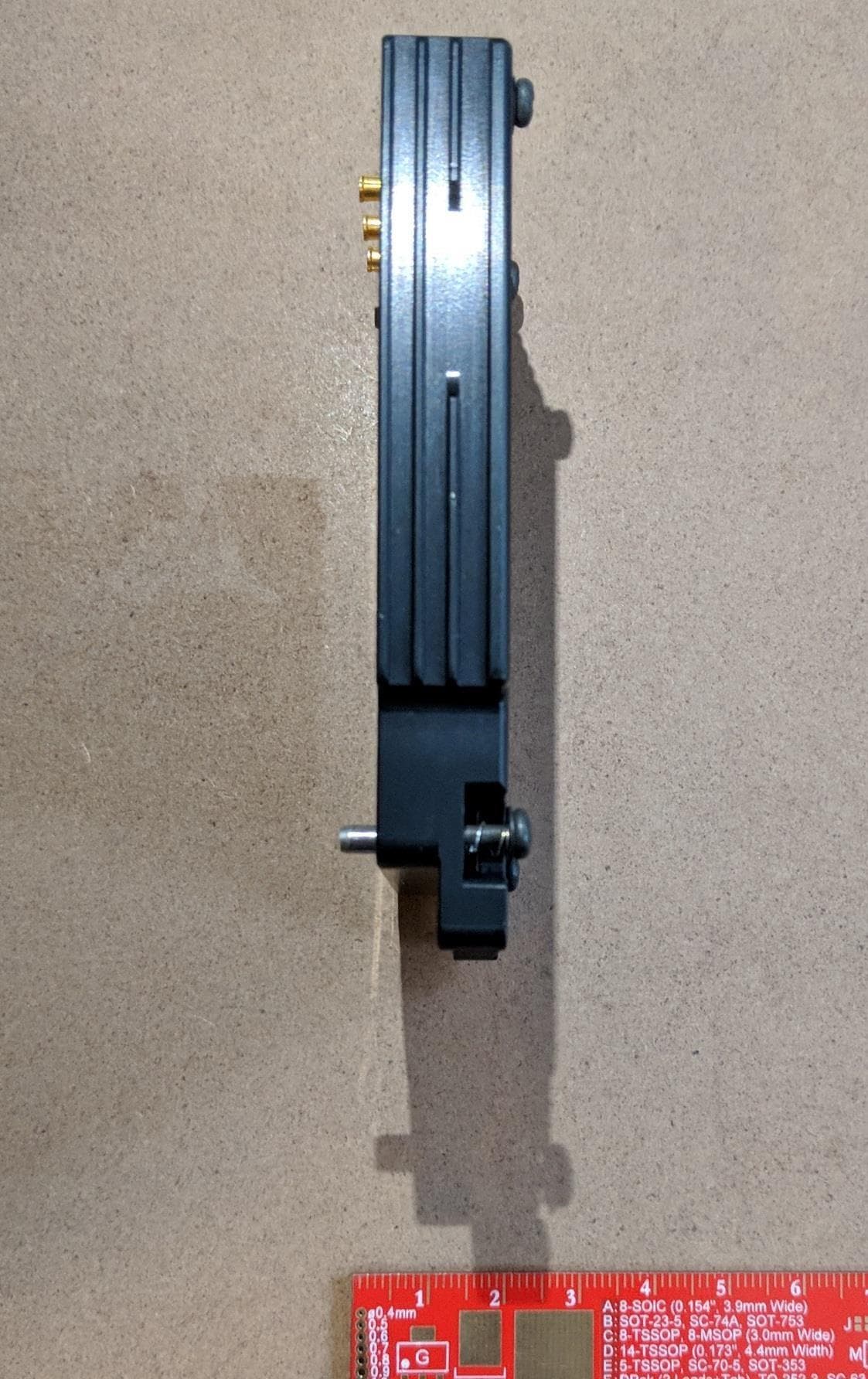
Click to zoom
Application Details
- Equipment Class
- DTS - Digital Transmission System
- Date of Grant
- Dec 08, 2025
- Application Purpose
- Original Equipment
- Equipment Note
- S-Band Interchangeable Frequency Module
- Frequency Range
- 2412.00000000 - 2462.00000000
- Company
- Persistent systems LLC
- Country
- United States
Documents & Files
Document Text
Text extracted from the exhibit documents filed with the FCC. Open a document above to read the original.
Users Manual
MPU5 (WR-5100) BASIC OPERATOR MANUAL VERSION 3.2 03EN073 Rev. P Copyright 2010 - 2025, Persistent Systems, LLC. All rights reserved. Wave Relay ® is a registered trademark of Persistent Systems, LLC (“Persistent”). This Basic Operator Manual (the “Manual”) contains information that is the sole property of Persistent Systems, LLC. Therefore, the Manual may not be excerpted, summarized, copied, distributed, or otherwise published, in whole or in part, without the prior written permission of Persistent Systems, LLC. All other product and service names, trademarks, logos, and brands are property of their respective owners. All non-Persistent company, product, and service names and all non-Per- sistent trademarks used in this Manual are for identification purposes only. Use of these non-Persistent names, trademarks, logos, and brands does not imply endorsement. Copyright 2010 - 2025 Persistent Systems, LLC Issued: November 2024 READ MANUAL BEFORE OPERATION DO NOT SWAP RF MODULES WHILE UNIT IS POWERED ON! DO NOT POWER ON UNIT WITHOUT ANTENNAS ATTACHED! PERSISTENT SYSTEMS Headquartered in New York City since 2007, Persistent Systems LLC is a global communications technology company that develops, manufactures, and integrates a patented and secure Mobile Ad Hoc Networking (MANET) system: the Wave Relay ® MANET. The company’s industry-leading R&D team has designed wireless networking protocols to support their cutting edge Wave Relay ® system and has designed leading-edge tactical networking devices that allow the Wave Relay ® MANET to achieve its highest potential. The Wave Relay ® MANET is capable of running real-time data, video, voice, and other applications under the most difficult and unpredictable conditions. Their suite of products is field proven and utilized in Commercial, Military, Government, Industrial, Agriculture, Mining, Oil and Gas, Robotics, and Unmanned System markets. THE MPU5 The MPU5 is the Next Generation Wave Relay ® platform. Leveraging multiple leading edge technologies such as MIMO and Android™, the MPU5 is a tactical networking device that delivers increased performance, reliability, and capability to the end user in a small, cost-efficient package. Stream multiple HD Video feeds, run commercial and custom apps, view situational awareness, and communicate with high quality audio all with a single device and a minimal number of accessories. WAVE RELAY ® MANET The Wave Relay ® MANET is a peer-to-peer wireless MANET networking solution in which there is no master node. If any device fails, the rest of the devices continue to communicate using any remaining connectivity. By eliminating master nodes, gateways, access points, and central coordinators from the design, the Wave Relay ® MANET delivers high levels of fault tolerance regardless of which nodes might fail. The network is designed to maximize the capacity of the radio frequency (RF) spectrum and to minimize the network overhead. While optimizing efficiency, the Wave Relay ® MANET also implements tech niques that increase multicast reliability. The advanced multicast functionality allows the system to support both multicast voice and video over IP. The Wave Relay ® MANET is designed to maintain high bandwidth con nectivity among devices that are on the move. The system is scalable, enabling it to incorporate unlimited meshed devices into the wireless network, where the devices themselves form the communication infrastructure. Even in highly dynamic environments, the system is able to maintain connectivity by rapidly re-routing data as necessary. The Wave Relay ® MANET is a self-forming and self-healing network where nodes can move freely within the network. Critical information flows reliably throughout the network while individual data paths are able to adapt at sub-second intervals. This unique approach creates an ideal environment for maximizing performance across the available communications medium. Customers leverage the Wave Relay ® MANET’s straightforward and effective architecture to enable a true “Plug and Play” capability. Deploying a Wave Relay ® MANET is as simple as connecting a standard Ethernet cable; customers are immediately connected to everything on the network. CONTACT PERSISTENT SYSTEMS Persistent Systems Tel: (212) 561-5895 | www.persistentsystems.com Persistent Systems Support & RMA https://www.persistentsystems.com/ps-support/ Persistent Systems Sales Email: [email protected] Persistent Systems Training Email: [email protected] © 2010 - 2025 Persistent Systems, LLC – All Rights Reserved NO NDA REQUIREDPAGE 6 OF 168 The export and/or the release of certain products, technology and software to non-US persons might be subject to export restrictions. Please refer to the US export laws & regulations for details. 03EN073 Rev. P Table of Contents Introduction 4 Persistent Systems 4 The MPU5 4 Wave Relay ® MANET 4 Safety 12 Suggested Hardware 16 Part I: Physical Setup 17 Section A: RF Setup 17 Inserting the RF Module 20 Connecting Antennas 22 Section B: Power 26 Connecting Power 28 Removing Power 30 Powering On the Unit 32 Section C: Side Connector Cables 34 © 2010 - 2025Persistent Systems, LLC – All Rights Reserved NO NDA REQUIRED The export and/or the release of certain products, technology and software to non-US persons might be subject to export restrictions. Please refer to the US export laws & regulations for details. 03EN073 Rev. PPAGE 7 OF 168 Table of Contents Parts List 35 Connecting a Cable to a Side Connector 35 Part II: Software Setup 38 Section A: Configuring the Management Computer 38 Parts List 38 Configuring the Management Computer (Windows) 40 Configuring the Management Computer (Linux) 45 Section B: Connecting the MPU5 to the Management Computer 46 Parts List 46 Section C: Accessing the Web Management Interface 49 Parts List 49 Section D: Basic Network Setup 57 Security Key 57 Assigning IP Address and Interface Names 59 Rebooting an Individual Node 62 © 2010 -…
Text truncated - open the document above for the full version.
Users Manual
ANT-2005 S-Band Omni Gooseneck Antenna Features ▶S-Band Antenna ▶Handles up to 50W power ▶Sleeve Dipole ▶Broad Band Coverage ▶Omni Radiation Pattern ▶Integrated RF Co-Axial Gooseneck ▶Black Chrome Non-Rotating RP-TNC Male Connector Specifications Frequency2.1 - 2.5 GHz Gain2.15 dBi VSWR<2:1 Impedance50 Ohms PolarizationVertical Omni or DirectionalOmni Horizontal Beamwidth360° Vertical Beamwidth77° RF Connector TypeRP-TNC(m) Non-Rotating RF Connector FinishBlack Chrome Length7.07 in / 18 cm Radome Diameter0.562 in / 1.4 cm Radome Length3.53 in / 9 cm Gooseneck Diameter0.350 in / 0.89 cm Gooseneck Length3 in / 7.6 cm Weight1.8 oz / 51 g Elevation Pattern Referenced to +5dBi © 2016 Persistent Systems, LLC. All rights reserved. The Wave Relay ® logo, the Persistent Systems, LLC logo and other designated trademarks and trade names are the property of Persistent Systems, LLC or their respective owners. Product specifications are subject to change without notice. This material is provided for informational purposes only; Persistent Systems, LLC assumes no liability related to its use and expressly disclaims any implied warranties of merchantability or fitness for any particular purpose. MADE IN USA persistentsystems.com | mpu5.comPersistent Systems, LLC | 303 Fifth Avenue, Suite 306 | New York, NY 10016 | O 212-561-5895 | F 212-202-3625 ONE SOLUTION. INFINITE POSSIBILITIES.
Users Manual
ANT-2010 S-Band 2.4 GHz 8.5 dBi Omnidirectional Antenna © 2016 Persistent Systems, LLC. All rights reserved. The Wave Relay ® logo, the Persistent Systems, LLC logo and other designated trademarks and trade names are the property of Persistent Systems, LLC or their respective owners. Product specifications are subject to change without notice. This material is provided for informational purposes only; Persistent Systems, LLC assumes no liability related to its use and expressly disclaims any implied warranties of merchantability or fitness for any particular purpose. MADE IN USA persistentsystems.com/MPU5Persistent Systems, LLC | 303 Fifth Avenue, Suite 306 | New York, NY 10016 | O 212-561-5895 | F 212-202-3625 ONE SOLUTION. INFINITE POSSIBILITIES. RELEASABLE Features ▶Compact, lightweight design ▶Durable UV-stable fiberglass radome ▶Vented end cap and drain holes in base ▶All weather operation ▶Can be installed in up or down positions Specifications Frequency2.2 - 2.5 GHz Gain8.5 dBi Impedance50 Ohm VSWR<2.0:1 avg. Maximum Input Power100W PolarizationVertical Vertical Beam Width15° Horizontal Beam Width360° Weight 0.5 lbs. 0.22 kg Length 20 in. 50.8 cm Base Diameter 1.27 in. 3.22 cm Radome Diameter 0.75 in. 1.9 cm Radome MaterialGray Fiberglass Wind Survival>150 mph Operating Temperature -40°C to +85°C -40°F to 185°F RoHS CompliantYe s Antenna ConnectorIntegral N-Male ANT-2010 S-Band 2.4 GHz 8.5 dBi Omnidirectional Antenna © 2016 Persistent Systems, LLC. All rights reserved. The Wave Relay ® logo, the Persistent Systems, LLC logo and other designated trademarks and trade names are the property of Persistent Systems, LLC or their respective owners. Product specifications are subject to change without notice. This material is provided for informational purposes only; Persistent Systems, LLC assumes no liability related to its use and expressly disclaims any implied warranties of merchantability or fitness for any particular purpose. MADE IN USA persistentsystems.com/MPU5Persistent Systems, LLC | 303 Fifth Avenue, Suite 306 | New York, NY 10016 | O 212-561-5895 | F 212-202-3625 ONE SOLUTION. INFINITE POSSIBILITIES. RELEASABLE Antenna Gain Pattern
Users Manual
ANT-2012 2.2 - 2.5 GHz 4 dBi High Performance Ground- to-Air Antenna © 2016 Persistent Systems, LLC. All rights reserved. The Wave Relay ® logo, the Persistent Systems, LLC logo and other designated trademarks and trade names are the property of Persistent Systems, LLC or their respective owners. Product specifications are subject to change without notice. This material is provided for informational purposes only; Persistent Systems, LLC assumes no liability related to its use and expressly disclaims any implied warranties of merchantability or fitness for any particular purpose. MADE IN USA persistentsystems.com | mpu5.comPersistent Systems, LLC | 303 Fifth Avenue, Suite 306 | New York, NY 10016 | O 212-561-5895 | F 212-202-3625 ONE SOLUTION. INFINITE POSSIBILITIES. Specifications Frequency2.2 - 2.5 GHz Gain4 dBi nom. PolarizationLinear (Vertical) Beamwidth360° (Az) x 40° (El) Approx. Cross Polar>20 dB Typ. VSWR 2:1 Max. 1.5:1 Typ. Power Rating30W Front to BackN/A Standard FinishMatte Black Length 8.86 in. 22.5 cm Diameter 1.06 in. 2.7 cm Weight 4.9 oz. 140 g ConnectorN-Type Male Temperature-30° to +70°C Wind Loading0.8 Kg (1.75 lbs) @ 100 mph *Previously WR-ANT-059 ANT-2012 2.2 - 2.5 GHz 4 dBi High Performance Ground- to-Air Antenna © 2016 Persistent Systems, LLC. All rights reserved. The Wave Relay ® logo, the Persistent Systems, LLC logo and other designated trademarks and trade names are the property of Persistent Systems, LLC or their respective owners. Product specifications are subject to change without notice. This material is provided for informational purposes only; Persistent Systems, LLC assumes no liability related to its use and expressly disclaims any implied warranties of merchantability or fitness for any particular purpose. MADE IN USA persistentsystems.com | mpu5.comPersistent Systems, LLC | 303 Fifth Avenue, Suite 306 | New York, NY 10016 | O 212-561-5895 | F 212-202-3625 ONE SOLUTION. INFINITE POSSIBILITIES. -50 -40 -30 -20 -10 0 10 90 80 70 60 50 40 30 20 10 0 -10 -20 -30 -40 -50 -60 -70 -80 -90 -100 -110 -120 -130 -140 -150 -160 -170 180 170 160 150 140 130 120 110 100 Co-Polar X-Polar -50 -40 -30 -20 -10 0 10 90 80 70 60 50 40 30 20 10 0 -10 -20 -30 -40 -50 -60 -70 -80 -90 -100 -110 -120 -130 -140 -150 -160 -170 180 170 160 150 140 130 120 110 100 Co-Polar X-Polar -50 -40 -30 -20 -10 0 10 90 80 70 60 50 40 30 20 10 0 -10 -20 -30 -40 -50 -60 -70 -80 -90 -100 -110 -120 -130 -140 -150 -160 -170 180 170 160 150 140 130 120 110 100 Co-Polar X-Polar -50 -40 -30 -20 -10 0 10 90 80 70 60 50 40 30 20 10 0 -10 -20 -30 -40 -50 -60 -70 -80 -90 -100 -110 -120 -130 -140 -150 -160 -170 180 170 160 150 140 130 120 110 100 Co-Polar X-Polar -50 -40 -30 -20 -10 0 10 90 80 70 60 50 40 30 20 10 0 -10 -20 -30 -40 -50 -60 -70 -80 -90 -100 -110 -120 -130 -140 -150 -160 -170 180 170 160 150 140 130 120 110 100 Co-Polar X-Polar -50 -40 -30 -20 -10 0 10 90 80 70 60 50 40 30 20 10 0 -10 -20 -30 -40 -50 -60 -70 -80 -90 -100 -110 -120 -130 -140 -150 -160 -170 180 170 160 150 140 130 120 110 100 Co-Polar X-Polar AzimuthElevation Peak Gain: 4.6 dBi Frequency: 2.390 GHz Beamwidth: 360° Max. X-Pol: -16.0 dB Peak Gain: 4.6 dBi Frequency: 2.390 GHz Beamwidth: 41.2° Max. X-Pol: -15.1 dB Peak Gain: 4.1 dBi Frequency: 2.450 GHz Beamwidth: 360° Max. X-Pol: -17.9 dB Peak Gain: 4.1 dBi Frequency: 2.450 GHz Beamwidth: 41.3° Max. X-Pol: -17.2 dB Peak Gain: 4.1 dBi Frequency: 2.500 GHz Beamwidth: 360° Max. X-Pol: -18.3 dB Peak Gain: 4.1 dBi Frequency: 2.500 GHz Beamwidth: 42.0° Max. X-Pol: -15.8 dB
Internal Photos
Picture 1: Front View w/o EMI Shield Picture 2: Front View w/ EMI Shield Picture 3: Back View
Test Setup Photos
TEST SETUP PHOTOS Persistent Systems LLC RF-2150(with MPU5 Host) FCC ID: 2AG3JRF-2150 FCCPart15 2 30-1000 MHZ FRONT VIEW 3 30-1000 MHZ REAR VIEW 4 1-18 GHZ FRONT VIEW 5 1-18 GHZ REAR VIEW 6 18-26 GHZ FRONT VIEW 7 18-26 GHZ REAR VIEW WWW.SGS.COM WWW.SGSGROUP.US.COM © SGS Group Management SA – 2018 – All rights reserved - SGS is a registered trademark of SGS Group Management SA
Test Report
Test Report Number: 4364134EMC05 Rev: 1 Persistent Systems LLC / RF-2150 Page: 1 of 97 Remarks: This document is issued by the Company subject to its General Conditions of Service printed overleaf, available on request or accessible at http://www.sgs.com//en/Terms-and-Conditions.aspx. And for electronic format documents, subject to Terms and Conditions for Electronic Documents at http://www.sgs.com/en/Terms-and-Conditions/terms-e-document.aspx. Attention is drawn to the limitation of liability, indemnification and jurisdiction issues defined therein. Any holder of this document is advised that information contained hereon reflects the Company’s findings at the time of its intervention only and within the limits of Client’s instructions, if any. The Company’s sole responsibility is to its Client and this document does not exonerate parties to a transaction from exercising all their rights and obligations under the transaction documents. This document cannot be reproduced except in full, without prior written approval of the Company. Any unauthorized alteration, forgery or falsification of the content or appearance of this document is unlawful and offenders may be prosecuted to the fullest extent of the law. Unless otherwise stated the results shown in this test report refer only to the sample(s) tested and such sample(s) are retained for a maximum of 30 days only. RF Test Report Project Number: 4364134 Proposal Number: 6939 Report Number: 4364134EMC05 Revision Level: 1 Client: Persistent Systems LLC Equipment Under Test: S-Band Interchangeable Frequency Module Model: RF-2150 FCC ID: 2AG3JRF-2150 Applicable Standards: ANSI C63.10:2013 FCC Part 15 Subpart C, § 15.247 Report issued on: 07 February 2025 Test Result: Compliant FOR THE SCOPE OF ACCREDITATION UNDER CERTIFICATE NUMBER: 3212.01 This report must not be used by the client to claim product certification, approval, or endorsement by A2LA, NIST, or any agency of the Federal Government. Tested by: Martin Taylor, Project Engineer Reviewed by: David Schramm, Operations Manager Test Report Number: 4364134EMC05 Rev: 1 Persistent Systems LLC / RF-2150 Page: 2 of 97 SGS North America Inc. Consumer and Retail 620 Old Peachtree Road NW, Suite 100, Suwanee, GA 30024 t (770) 570-1800 www.sgs.com Member of the SGS Group (SGS SA) Table of Contents 1 SUMMARY OF TEST RESULTS ..................................................................................................................................... 4 1.1 MODIFICATIONS REQUIRED FOR COMPLIANCE .............................................................................................................. 4 2 GENERAL INFORMATION ............................................................................................................................................. 5 2.1 CLIENT INFORMATION ................................................................................................................................................... 5 2.1 TEST LABORATORY ....................................................................................................................................................... 5 2.2 GENERAL INFORMATION OF EUT .................................................................................................................................. 5 2.3 OPERATING MODES AND CONDITIONS .......................................................................................................................... 6 2.4 EUT POWER TABLES ..................................................................................................................................................... 7 2.5 EUT CONNECTION BLOCK DIAGRAM ............................................................................................................................ 8 2.6 SYSTEM COMPONENT IDENTIFICATION.......................................................................................................................... 9 2.7 CABLE LIST ................................................................................................................................................................... 9 3 BANDWIDTH ................................................................................................................................................................... 10 3.1 TEST RESULT ............................................................................................................................................................... 10 3.2 TEST METHODS ........................................................................................................................................................... 10 3.3 TEST SITE .................................................................................................................................................................... 11 3.4 TEST EQUIPMENT ........................................................................................................................................................ 11 3.5 TEST SETUP PHOTOGRAPHS ......................................................................................................................................... 11 3.6 TEST DATA .................................................................................................................................................................. 12 3.7 PLOTS – 6DB BANDWIDTH........................................................................................................................................... 13 3.8 PLOTS – 99% BANDWIDTH .......................................................................................................................................... 16 4 FUNDAMENTAL EMISSION OUTPUT POWER ....................................................................................................... 19 4.1 TEST RESULT ..............................................................................................................…
Text truncated - open the document above for the full version.
Test Report
Test Report Number: 4364134EMC03 Rev: 2 Persistent Systems / RF-2150 Page: 1 of 15 Remarks: This report details the results of the testing carried out on one sample, the results contained in this test report do not relate to other samples of the same product. The manufacturer should ensure that all products in series production are in conformity with the product sample detailed in this report. This document is issued by the Company under its General Conditions of Service accessible at http://www.sgs.com/en/Terms-and- Conditions.aspx. Attention is drawn to the limitation of liability, indemnification and jurisdiction issues defined therein. Any holder of this document is advised that information contained hereon reflects the Company’s findings at the time of its intervention only and within the limits of Client’s instructions, if any. The Company’s sole responsibility is to its Client and this document does not exonerate parties to a transaction from exercising all their rights and obligations under the transaction documents. Any unauthorized alteration, forgery or falsification of the content or appearance of this document is unlawful and offenders may be prosecuted to the fullest extent of the law. RF Exposure Report Project Number: 4364134 Proposal Number: 6939 Report Number: 4364134EMC03 Revision Level: 2 Client: Persistent Systems LLC Equipment Under Test: S-Band Interchangeable Frequency Module Model: RF-2150 Applicable Standards: 47 C.F.R. §§ 2.1091 FCC KDB 447498 D01 General RF Exposure Guidance v06 Prepared by: Martin Taylor, Project Engineer Reviewed by: Stephen Whalen, EMC Lab Manager Test Report Number: 4364134EMC03 Rev: 2 Persistent Systems / RF-2150 Page: 2 of 15 SGS North America Inc. Consumer and Retail 620 Old Peachtree Road NW, Suite 100, Suwanee, GA 30024 t (770) 570-1800 www.sgs.com Member of the SGS Group (SGS SA) TABLE OF CONTENTS 1 GENERAL INFORMATION ............................................................................................................................................. 3 1.1 CLIENT INFORMATION ................................................................................................................................................... 3 1.1 TEST LABORATORY ....................................................................................................................................................... 3 1.2 GENERAL INFORMATION OF EUT .................................................................................................................................. 3 1.3 OPERATING MODES AND CONDITIONS .......................................................................................................................... 3 2 RF EXPOSURE ................................................................................................................................................................... 4 2.1 TEST RESULT ................................................................................................................................................................. 4 2.2 TEST METHOD ............................................................................................................................................................... 4 2.3 EUT PHOTOGRAPHS ...................................................................................................................................................... 4 2.4 SINGLE, DOUBLE, TRIPLE TRANSMISSION RF EXPOSURE LEVELS (MW/CM 2 )................................................................ 6 3 REVISION HISTORY ...................................................................................................................................................... 15 Test Report Number: 4364134EMC03 Rev: 2 Persistent Systems / RF-2150 Page: 3 of 15 SGS North America Inc. Consumer and Retail 620 Old Peachtree Road NW, Suite 100, Suwanee, GA 30024 t (770) 570-1800 www.sgs.com Member of the SGS Group (SGS SA) 1 General Information 1.1 Client Information Name: Persistent Systems LLC Address: 303 Fifth Ave. Suite 306 City, State, Zip, Country: New York, New York 10016, USA 1.1 Test Laboratory Name: SGS North America, Inc. Address: 620 Old Peachtree Road NW, Suite 100 City, State, Zip, Country: Suwanee, GA 30024, USA Accrediting Body: A2LA Type of lab: Testing Laboratory Certificate Number: 3212.01 1.2 General Information of EUT Equipment Under Test: S-Band Interchangeable Frequency Module Model: RF-2150 Serial Number: 33079 Host Marketing Name: MPU5 Frequency Range: 2412 to 2462 MHz Modulation: 802.11 bgn Antenna: ANT-2010 (8.5 dBi), ANT-2012 (4.1 dBi), ANT-2005 (2.15 dBi) Sample Received Date: 17 September 2018 Dates of testing: 19 September to 17 December 2018 1.3 Operating Modes and Conditions Evaluation was performed as specified in FCC KDB 558074 D01 v05 and FCC KDB 447498 D01. Test Report Number: 4364134EMC03 Rev: 2 Persistent Systems / RF-2150 Page: 4 of 15 SGS North America Inc. Consumer and Retail 620 Old Peachtree Road NW, Suite 100, Suwanee, GA 30024 t (770) 570-1800 www.sgs.com Member of the SGS Group (SGS SA) 2 RF Exposure 2.1 Test Result Test Description Product Specific Standard Test Result RF Exposure FCC Part 1.1310 Compliant 2.2 Test Method Using the maximum power (including tune-up tolerances), the power density was calculated. Maximum antenna gain was provided by the client for this exercise. 2.3 EUT Photographs EUT with 3 high-gain (8.5dBi) antennas Test Report Number: 4364134EMC03 Rev: 2 Persistent Systems / RF-2150 Page: 5 of 15 SGS North America Inc. Consumer and Retail 620 Old Peachtree Road NW, Suite 100, Suwanee, GA 30024 t (770) 570-1800 www.sgs.com Member of the SGS Group (SGS SA) EUT with 3 medium-gain (4.1dBi) antennas EUT with 3 low-gain (2.15dBi) antennas Test Report Number: 4364134EMC03 Rev: 2 Persistent Systems / RF-2150 Page: 6 of 15 SGS North America Inc. Consumer and Retail 620 Old Peachtree Road NW, Suite 100, Suwanee, GA 30024 t (770) 570-1800 www.…
Text truncated - open the document above for the full version.
RF Exposure Info
© 2019 RF Exposure Lab, LLC This report shall not be reproduced except in full without the written approval of RF Exposure Lab, LLC. 802 N. Twin Oaks Valley Road, Suite 105 • San Marcos, CA 92069 • U.S.A. TEL (760) 471-2100 • FAX (760) 471-2121 http://www.rfexposurelab.com CERTIFICATE OF COMPLIANCE SAR EVALUATION Persistent Systems Dates of Test: January 30-31, 2019 303 Fifth Avenue Suite 306 Test Report Number: SAR.20190107 New York, NY 10016 Revision A This wireless mobile and/or portable device has been shown to be compliant for localized specific absorption rate (SAR) for uncontrolled environment/general exposure limits specified in ANSI/IEEE Std. C95.1-1992 and had been tested in accordance with the measurement procedures specified in IEEE 1528-2013 and IEC 62209-2:2010 (See test report). I attest to the accuracy of the data. All measurements were performed by myself or were made under my supervision and are correct to the best of my knowledge and belief. I assume full responsibility for the completeness of these measurements and vouch for the qualifications of all persons taking them. RF Exposure Lab, LLC certifies that no party to this application is subject to a denial of Federal benefits that includes FCC benefits pursuant to Section 5301 of the Anti-Drug Abuse Act of 1988, 21 U.S.C. 853(a). Jay M. Moulton Vice President Testing Cert. # 2387.01 FCC ID: 2AG3J-RF2150 IC Certificate: 20968-RF2150 Model(s): RF-2150 Test Sample: Engineering Unit Same as Production Serial Number: 35908 Equipment Type: Wireless Mobile Ad Hoc Networking Radio (MANET) Classification: Portable Transmitter Near to Body TX Frequency Range: 2412 – 2462 MHz Frequency Tolerance: ± 2.5 ppm Maximum RF Output: 2450 MHz (b) – 27.00 dBm, 2450 MHz (g) – 27.00 dBm, 2450 MHz (n20) – 27.00 dBm, 2450 MHz (n40) – 27.00 dBm Conducted Signal Modulation: DSSS, OFDM Antenna Type: External Whip Antenna Application Type: Certification FCC Rule Parts: Part 2, 15C, 15E KDB Test Methodology: KDB 447498 D01 v06, KDB 248227 v02r02 Industry Canada: RSS-102 Issue 5, Safety Code 6 Maximum SAR Value: 0.85 W/kg Reported Maximum Simultaneous SAR: 0.04 Separation Ratio Separation Distance: 50 mm Report Number: SAR.20190107 © 2019 RF Exposure Lab, LLC Page 2 of 61 This report shall not be reproduced except in full without the written approval of RF Exposure Lab, LLC. Table of Contents 1. Introduction ........................................................................................................................ 3 SAR Definition [5] ................................................................................................................... 4 2. SAR Measurement Setup ................................................................................................... 5 Robotic System ...................................................................................................................... 5 System Hardware ................................................................................................................... 5 System Electronics ................................................................................................................. 6 Probe Measurement System .................................................................................................. 6 3. Probe and Dipole Calibration .............................................................................................14 4. Phantom & Simulating Tissue Specifications .....................................................................15 Head & Body Simulating Mixture Characterization ................................................................15 5. ANSI/IEEE C95.1 – 1992 RF Exposure Limits [2] ..............................................................16 Uncontrolled Environment .....................................................................................................16 Controlled Environment .........................................................................................................16 6. Measurement Uncertainty .................................................................................................17 7. System Validation..............................................................................................................18 Tissue Verification ...........................................................................................…
Text truncated - open the document above for the full version.
Contact Information
Applicant
David Holmer(CTO and Cofounder)
[email protected]Fax: 212-202-3625
Technical Contact
SGS North America, Inc.Martin Taylor
620 Old Peachtree Rd NW · Suwanee, 30024 · United States
Test Firm
SGS North America, Inc.David Schramm
[email protected]Fax: 973 575 7175
Technical Specifications
| # | Rule Parts | Frequency Range | Power Output |
|---|---|---|---|
| 1 | 15C | 2.41 GHz - 2.46 GHz | 955.00 mW |