2AG5R85106712V 4 Channel Wireless Remote Control Module
C.G. Motor Sports Inc.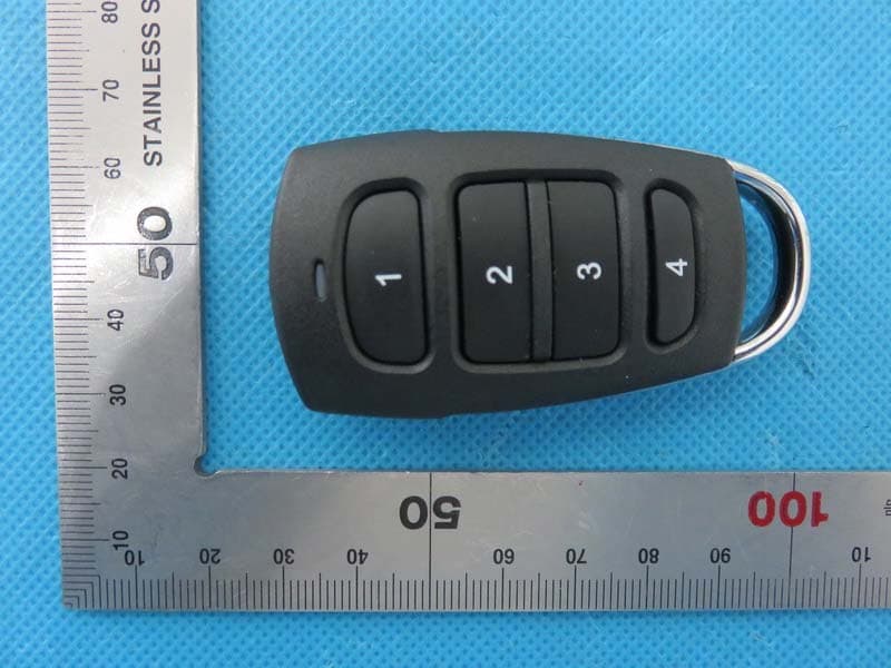
Click to zoom
Application Details
- Equipment Class
- DSC - Part 15 Security/Remote Control Transmitter
- Date of Grant
- Jan 26, 2016
- Application Purpose
- Original Equipment
- Date of Application
- Jan 26, 2016
- Equipment Note
- 12V 4 Channel Wireless Remote Control Module
- Frequency Range
- 315.00000000 - 315.00000000
- Company
- C.G. Motor Sports Inc.
- Country
- United States
Documents & Files
Document Text
Text extracted from the exhibit documents filed with the FCC. Open a document above to read the original.
Users Manual
Universal 4 Channel Remote Control -Key FOB -Power module Step 1 Find a suitable place in the engine compartment close to the battery to mount the control module. Step 2 Once you have mounted the control module run your power and ground wires to the control module. There are 4 channels and they are ON/OFF function. Each channel can handle a max load of 20 amps. amps should be wired with an external 30 amp on. Be sure not to exceed this. The -/+ labels are stamped on the housing and go from left to right negative being first and positive being second for each channel. (Refer to image Step 3 Now that your module is mounted an from the module to the battery and your installation is complete from 1 to 4 and this represents each channel. Press once to turn accessory ON and again to turn it OFF. NOTE : This unit has a built in voltage protection circuit and will shut off once voltage drops below 10 volts AnzoUSA™ products are covered, by a limited one (1) year war product categories have warranty policies which differ from this standard, please contact your representative for detailed ca information. Damage due to improper installation or replace the product proven to be defective. Neither seller nor manufacturer shall be liable for any injury, loss or damage, d consequential, arising out of the use of or the inability to use the product. Before using, user shall determine the suitability of the product for its intended use, and user assumes all risk and liability whatsoever in connection therewith. Universal 4 Channel Remote Control Part number 851067 Kit contents: Power module -Velcro -3m double sided tape Find a suitable place in the engine compartment close to the battery to mount the control module. have mounted the control module run your power and ground wires to the control module. There are 4 channels and they are ON/OFF function. Each channel can handle a max load of 20 amps. Any products exceeding 15 amps should be wired with an external 30 amp relay. This unit will trigger the relay which will then turn your accessory /+ labels are stamped on the housing and go from left to right negative being first each channel. (Refer to image) Now that your module is mounted and your connections are made, connect the power to the battery and your installation is complete and ready to use. Your supplied Key FOB is numbered epresents each channel. Press once to turn accessory ON and again to turn it OFF. : This unit has a built in voltage protection circuit and will shut off once voltage drops below 10 volts AnzoUSA™ products are covered, by a limited one (1) year warranty, to be free of manufacturer’s defects. However, certain AnzoUSA™ product categories have warranty policies which differ from this standard, please contact your representative for detailed ca information. Damage due to improper installation or road hazards is not covered. Seller and manufacturers’ only obligations shall be to replace the product proven to be defective. Neither seller nor manufacturer shall be liable for any injury, loss or damage, d use of or the inability to use the product. Before using, user shall determine the suitability of the product for its intended use, and user assumes all risk and liability whatsoever in connection therewith. 3m double sided tape Find a suitable place in the engine compartment close to the battery to mount the control module. have mounted the control module run your power and ground wires to the control module. There are Any products exceeding 15 relay. This unit will trigger the relay which will then turn your accessory /+ labels are stamped on the housing and go from left to right negative being first nect the power (red) and ground (black) and ready to use. Your supplied Key FOB is numbered epresents each channel. Press once to turn accessory ON and again to turn it OFF. : This unit has a built in voltage protection circuit and will shut off once voltage drops below 10 volts ranty, to be free of manufacturer’s defects. However, certain AnzoUSA™ product categories have warranty policies which differ from this standard, please contact your representative for detailed category road hazards is not covered. Seller and manufacturers’ only obligations shall be to replace the product proven to be defective. Neither seller nor manufacturer shall be liable for any injury, loss or damage, direct or use of or the inability to use the product. Before using, user shall determine the suitability of the product for its intended use, and user assumes all risk and liability whatsoever in connection therewith. N OTE : This equipment has been tested and found to comply with the limits for a Class B digital device, pursuant to part 15 of the FCC Rules. These limits are designed to provide reasonable protection against harmful interference in a residential installation. This equipment generates, uses and can radiate radio frequency energy and, if not installed and used in accordance with the instructions, may cause harmful interference to radio communications. However, there is no guarantee that interference will not occur in a particular installation. If this equipment does cause harmful interference to radio or television reception, which can be determined by turning the equipment off and on, the user is encouraged to try to correct the interference by one or more of the following measures: —Reorient or relocate the receiving antenna. —Increase the separation between the equipment and receiver. —Connect the equipment into an outlet on a circuit different from that to which the receiver is connected. —Consult the dealer or an experienced radio/TV technician for help. This device complies with part 15 of the FCC rules. Operation is subject to the following two conditions: (1) this device may not cause harmful interference, and (2) this device must accept any interference received, including interference that may cause undesired operation. Changes or modifications to this unit not expressly approved by t…
Text truncated - open the document above for the full version.
Attestation Statements
C.G. Motor Sports Inc. 5150 Eucalyptus Ave Chino California 91710 United States TEL: 1-909-628-1440 FAX: 1-909-628-0076 Federal Communications Commission Authorization and Evaluation Division Equipment Authorization Branch 7435 Oakland Mills Road Columbia, MD 21046 1/22/2016 To whom it may concern: We, the undersigned, hereby authorize Eurofins Product Service GmbH to act on our behalf in all matters relating to applications for equipment authorization FCC ID: 2AG5R851067 including the signing of all documents related to these matters. Any and all acts carried out by Eurofins Product Service GmbH on our behalf shall have the same effect as acts of our own. We also hereby certify that no party to this application is subject to a denial of benefits, including FCC benefits, pursuant to Section 5301 of the Anti-Drug Abuse Act of 1988, 21 U.S.C. 862. Sincerely, Signature C.G. Motor Sports Inc. Contact person: Shaun Callaway Title: Manager
Cover Letter(s)
C.G. Motor Sports Inc. 5150 Eucalyptus Ave Chino California 91710 United States TEL: 1-909-628-1440 FAX: 1-909-628-0076 Federal Communications Commission Equipment Authorization Branch 7435 Oakland Mills Road Columbia, MD 21046 1/22/2016 Request for Confidentiality Company name: C.G. Motor Sports Inc. FCC ID: 2AG5R851067 FCC Part 15 Certification Gentlemen, In accordance with CFR 47 § 0.459, C.G. Motor Sports Inc. hereby requests confidentiality of following attachments: (1) schematic diagrams, (2) detailed block diagrams, (3) detailed operational descriptions, (4) detailed parts list These documents contain detailed system and equipment description and related information about the product which C.G. Motor Sports Inc. considers to be proprietary, confidential and a custom design and otherwise would not release to the general public. Since the design is a basis from which future technological products will evolve, C.G. Motor Sports Inc. considers that this information would be of benefit to its competitors and that the disclosure of the information in these documents would give competitors an unfair advantage in the market. Sincerely, Signature [Shaun Callaway] [Manager] C.G. Motor Sports Inc. 5150 Eucalyptus Ave Chino California 91710 United States
External Photos
External Photos TOP VIEW OF EUT BOTTOM VIEW OF EUT FRONT VIEW OF EUT BACK VIEW OF EUT LEFT VIEW OF EUT RIGHT VIEW OF EUT
ID Label/Location Info
FCC ID Label Location Model:851067 FCC ID: 2AG5R851067
Internal Photos
Internal Photos OPEN VIEW OF EUT INTERNAL VIEW OF EUT-1 INTERNAL VIEW OF EUT-2 INTERNAL VIEW OF EUT-3
Operational Description
C.G. Motor Sports Inc. 5150 Eucalyptus Ave Chino California 91710 United States TEL: 1-909-628-1440 FAX: 1-909-628-0076 Declaration concerning Antenna Specification It is hereby declared that the product Model No.: 851067 FCC ID: 2AG5R851067 fulfills the requirement in FCC test relating to the antenna type. The device specified above confirms to the FCC recommendations for internal antenna type described below: Model No. of antenna: N/A Type of antenna: PCB Antenna Gain of the antenna: 0 dBi Frequency range: 315 MHz The mounting of the antenna is fixed to the radio module and no other antenna should be used. Company name: C.G. Motor Sports Inc. Address: 5150 Eucalyptus Ave Chino City: California ZIP / Postal code: 91710 Country: United States Place: Shenzhen Date: Jan.21,2016 Signature:
RF Exposure Info
RF Exposure evaluation Product Description: 12V 4 Channel Wireless Remote Control Module Model Number: 851067 FCC ID: 2AG5R851067 According to 447498 D01 General RF Exposure Guidance v05 The 1-g and 10-g SAR test exclusion thresholds for 100 MHz to 6 GHz at test separation distances ≤ 50 mm are determined by: [(max. power of channel, including tune-up tolerance, mW)/(min. test separation distance, mm)] ·[√f(GHz)] ≤ 3.0 for 1-g SAR and ≤ 7.5 for 10-g extremity SAR, where f(GHz) is the RF channel transmit frequency in GHz Power and distance are rounded to the nearest mW and mm before calculation According to the follow transmitter output power(P t )formula: P t =(E x d) 2 /(30 x g t ) P t =transmitter output power in watts g t =numeric gain of the transmitting antenna (unitess) E=electric field strength in V/m d=measurement distance in meters (m) According to the above test data, Emax=66.12dBuv/m=0.002018V/m,d=3m,g t =1 P t =(E x d) 2 /(30 x g t )=(0.002018x3) 2 /(30x1)=0.00000122W=0.0012mW The result is rounded to one decimal place for comparison Worse case is as below: [315MHz -0.0012mW output power] (0.0012mW /5mm) .[√0.315GHz)]= 0.00013<3.0 for 1-g SAR Then SAR evaluation is not required NOTE: For the maximum power, you can refer FCC test report.
Test Report
FCC ID APPLI PROD U BRAND MODE CLIEN DATE O STAND REPOR A CAUTIO This rep laborato D CATION P U UCT DESIG D NAME EL NAME T OF ISSUE DARD(S) RT VERSIO Attestat ON: port shall n ory and sha FC Rep URPOSE GNATION ON tion of G not be repro all not be q C Te port No.: : 2AG5 : Origi : 12V 4 : ANZO : 8510 : C.G. M : Jan.0 : FCC P : V1.0 Global C oduced exc quoted out o est R AGC0561 5R851067 inal Equipm 4 Channel W O USA 067 Motor Spor 04, 2016 Part 15 Rul Complia cept in full w of context. Rep 18151201 ment Wireless R rts Inc. les ance (Sh without the port 1FE03 Remote Con henzhen e written p t ntrol Modul n) Co., L permission Page 1 le Ltd of the test of 27 AGC05618151201FE03 Page 2 of 27 Report Revise Record Report Version Revise Time Issued Date Valid VersionNotes V1.0 / Jan.04, 2016Valid Original Report AGC05618151201FE03 Page 3 of 27 TABLE OF CONTENTS 1. VERIFICATION OF CONFORMITY ............................................................................................................ 4 2. GENERAL INFORMATION ........................................................................................................................ 5 2.1. PRODUCT DESCRIPTION ................................................................................................................. 5 2.2. RELATED SUBMITTAL(S) / GRANT (S) ............................................................................................. 5 2.3. TEST METHODOLOGY ...................................................................................................................... 5 2.4. SPECIAL ACCESSORIES .................................................................................................................. 5 2.5. EQUIPMENT MODIFICATIONS .......................................................................................................... 5 3. MEASUREMENT UNCERTAINTY ............................................................................................................. 6 4. DESCRIPTION OF TEST MODES ............................................................................................................. 6 5. SYSTEM TEST CONFIGURATION ............................................................................................................ 7 5.1. EQUIPMENT USED IN EUT SYSTEM ................................................................................................ 7 5.2. SUMMARY OF TEST RESULTS ......................................................................................................... 7 6. TEST FACILITY .......................................................................................................................................... 8 7. ANTENNA REQUIREMENT ....................................................................................................................... 9 8. PROVISION FOR MOMENTARY OPERATION ....................................................................................... 10 8.1 MEASUREMENT PROCEDURE ....................................................................................................... 10 8.2 TEST SETUP ..................................................................................................................................... 10 8.3 TEST RESULT .................................................................................................................................... 11 9. DUTY CYCLE CORRECTION FACTOR .................................................................................................. 12 9.1 MEASUREMENT PROCEDURE ....................................................................................................... 12 9.2 TEST SETUP ..................................................................................................................................... 12 9.3 TEST RESULT ................................................................................................................................... 13 10. RADIATED EMISSION ........................................................................................................................... 15 10.1. MEASUREMENT PROCEDURE .................................................................................................... 15 10.2. TEST SETUP .................................................................................................................................. 17 10.3. TEST RESULT ................................................................................................................................ 18 11. BANDWIDTH .......................................................................................................................................... 20 11.1. MEASUREMENT PROCEDURE ..................................................................................................... 20 11.2. TEST SETUP .................................................................................................................................. 20 11.3. TEST RESULT ................................................................................................................................ 21 APPENDIX A: PHOTOGRAPHS OF TEST SETUP ..................................................................................... 22 APPENDIX B: PHOTOGRAPHS OF EUT .................................................................................................... 23 AGC05618151201FE03 Page 4 of 27 1. VERIFICATION OF CONFORMITY Applicant C.G. Motor Sports Inc. Address 5150 Eucalyptus Ave, Chino, CA 91710, U.S.A. Manufacturer Luckystar Electronic Technology Co., Ltd. Address Qingzhou Development Zone, Xi'an Town, Gaoming District, Foshan, China Product Designation 12V 4 Channel Wireless Remote Control Module Brand Name ANZO USA Test Model: 851067 Date of test Dec.29, 2015 to Dec.31, 2015 Deviation None Condition of Test Sample Normal Report Template AGCRT-US-BR/RF (2013-03-01) We hereby certify that: The above equipment was tested by Dongguan Pre…
Text truncated - open the document above for the full version.
Test Setup Photos
APPENDIX IV PHOTOGRAPHS OF TEST SETUP RADIATED EMISSION TEST SETUP BELOW 1GHz RADIATED EMISSION TEST SETUP ABOVE 1GHz
Contact Information
Applicant
Shaun Callaway
Test Firm
Dongguan Precise Testing Service Co., Ltd.Chris Du
Technical Specifications
| # | Rule Parts | Frequency Range | Power Output |
|---|---|---|---|
| 1 | 15.231 | 315 MHz - 315 MHz | - |