2AG9Y-GMR-7V1MARINE & POWERSPORTS
MAXXSONICS USA INC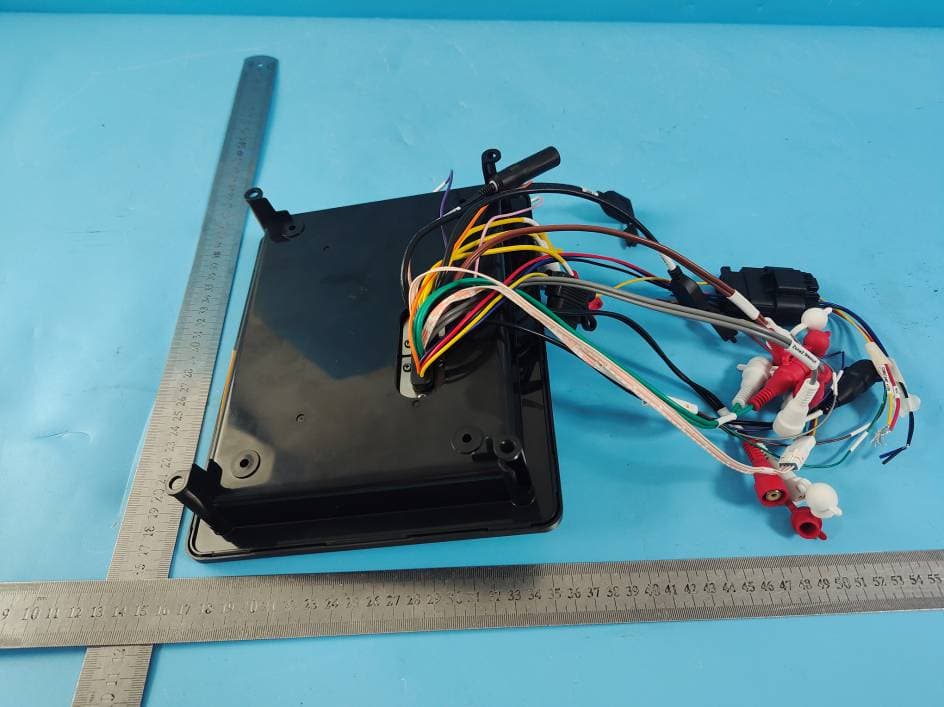
Click to zoom
Application Details
- Equipment Class
- DSS - Part 15 Spread Spectrum Transmitter
- Date of Grant
- Jan 05, 2023
- Application Purpose
- Original Equipment
- Date of Application
- Jan 05, 2023
- Equipment Note
- MARINE & POWERSPORTS
- Frequency Range
- 2402.00000000 - 2480.00000000
- Company
- MAXXSONICS USA INC
- Country
- United States
Documents & Files
Document Text
Text extracted from the exhibit documents filed with the FCC. Open a document above to read the original.
Users Manual
1 OWNER’S MANUAL GMR-7V1 2 CONTENT SAFETY INFORMATION ....................................................................................... 3‐4 INSTALLATION ................................................................................................... 5‐6 ELECTRICAL CONNECTION ..................................................................................... 7 THE PLAYER ................................................................................................................................ 8 MAIN MENU ................................................................................................................................ 9 RADIO OPERATION.......................................................................................................................... 10‐11 USB MEDIA PLAYER OPERATION ...............................................................................................12‐14 BLUETOOTH OPERATION ............................................................................................................ .14‐17 AUX IN OPERATION ............................................................................................................................... 17 CAMERA 1 OPERATION ........................................................................................................................ 17 CAMERA 2 OPERATION ....................................................................................................................... 18 EXTERNAL MONITOR OPERATION ................................................................................................. 18 EQUALIZER OPERATION .................................................................................................................... 18 SETTINGS OPERATION ................................................................................................................. 19‐21 COMMON PROBLEMS AND SOLUTIONS ................................................................. 22 3 SAFETY INFORMATION Use This Product Safely This set has been designed and manufactured to assure personal safety. Improper use can result in electric shock or fire hazard. The safeguards incorporated in this unit protect you if you observe the following procedures for installation, use and servicing. This unit doesn’t contain any parts that can be repaired by the user. When Driving Keep the volume level low enough to be aware of road and traffic conditions. When Car Washing Do not expose the product to water or excessive moisture. This could cause electrical shorts, fire or other damage. When Parked Parking in direct sunlight can produce very high temperatures inside your vehicle. Give the interior a chance to cool down before starting playback. Use the Proper Power Supply This product is designed to operate with a 12 volt DC Use Authorized Service Centers Do not attempt to disassemble or adjust this precision product. Please refer to the Service Center list included with this product for service assistance. For Installation The unit should be installed in a horizontal position with the front end up at a convenient angle, but not more than 30 0 . Notes: Choose the mounting location where the unit will not interfere with the normal driving function of the driver. Before finally installing the unit, connect the wiring temporarily and make sure it is all connected up properly and the unit and the system work properly. Use only the parts included with the unit to ensure proper installation. The use of unauthorized parts can cause malfunctions. Consult with your nearest dealer if installation requires the drilling of holes or other modifications of the vehicle. Install the unit where it does not get in the driver’s way and cannot injure the passenger if there is an emergency stop. If installation angel exceeds 30°from horizontal, the unit might not give its optimum performance. 30 4 INSTALLATION Avoid installing the unit where it would be subject to high temperature, such as from direct sunlight, or from hot air, from the heater, or where it would be subject to dust, dirt or excessive vibration. Installation Method Step 1: Remove the plastic outer frame and outer frame sealing silicone. Step 2: put the unit on the base. Step 3: Take four screws and four mounting brackets from the attachment, Tighten the screws and mounting brackets to secure the unit to the base. Step 4: Put the outer frame sealing silicone and plastic outer frame. 5 INSTALLATION ATTENTIONS OF INSTALLATION 1.This player should be installed by professional technician. 2. please read the instruction and operation of equipment carefully before installing. 3. Make sure to connect other wires before power connection. 4. To avoid short circuit. Please make sure all the exposed wire are insulating. 5. Please fix all the wires after installation. 6. Please make connection to the player accordingly to this instruction manual. Wrong connection may cause damage. 7. This player only fit for 12V DC device and please make sure your car belongs to this kind of cathode grounding electrical system. 8. Please connect the wires rightly. Wrong connection will cause malfunction or damage the electrical system. 6 ELECTRICAL CONNECTON Attention: 1. Please make sure “CONSTANT +12V”and ”ACC” pin location are correct before making connection 2. This player can only be used by the 12V DC cathode grounding electrical system. 3. Don’t connect the terminals of the car battery until the player is absolutely with well erection joint. 4. Please make sure to connect the yellow wire to the positive of the battery (+) or constant +12V. 5. When change the fuse. Please make sure the specifications are same. 6. Using good quality speaker with 4‐8 ohm can result in the best effect of the equipment. 7. Connect iPhone to product via USB1 port, User can also go to Apple CarPlay 7 THE PLAYER 1.Touch screen user interface 2/6.Subwoofer volume down/ up 3.Zone1 mute 4. Rotary VOL knob to adju…
Text truncated - open the document above for the full version.
Attestation Statements
Model difference letter 2022.12.25 Dear MET Reviewer, This is a new Application from MAXXSONICS USA INC Model No.: GMR-7V1, GMR-7CFM Use GMR-7V1 for all tests. Only the model name is different. Thank you for your cooperation! Yours sincerely, Signatory: Name: BrianSherman Position: Director of Business Development Company Name: MAXXSONICS USA INC Address: 851 E. Park Avenue, Libertyville, Illinois, United States, 60048 Tel / Fax 8475407700/8475409776 E-Mail: [email protected]
Cover Letter(s)
MAXXSONICS USA INC Agent Authorization Letter 2022-12-25 Eurofins Electrical and Electronic Testing NA, Inc. 914 West Patapsco Avenue Baltimore, MD 21230 USA RE: LETTER OF AGENT AUTHORIZATION To Whom It May Concern: We, the undersigned, hereby authorize Shenzhen Most Technology Service Co., Ltd. to act on our behalf in all matters relating to application for equipment authorization, including the signing of all documents relating to these matters. We also hereby certify that no party to the application authorized hereunder is subject to the denial of benefits, including FCC benefits, pursuant to Section 5301 of the Anti-Drug Abuse Act of 1988, 21 U.S.C.853(a). This agreement expires one year from the current date. Sincerely, Name: BrianSherman Position: Director of Business Development Company Name: MAXXSONICS USA INC Address: 851 E. Park Avenue, Libertyville, Illinois, United States, 60048 Tel / Fax 8475407700/8475409776 E-Mail: [email protected]
Cover Letter(s)
MAXXSONICS USA INC Long Term Confidentiality Request Letter 2022-12-25 Eurofins Electrical and Electronic Testing NA, Inc. 914 West Patapsco Avenue Baltimore, MD 21230 USA RE: CONFIDENTIALITY REQUEST FOR (FCC ID: 2AG9Y-GMR-7V1) To Whom It May Concern: This letter serves as an official request for confidentiality under sections 0.457 and 0.459 of CFR 47. We have requested that the - e.g. Block diagram - e.g. SCH - e.g. Operational Description required to be submitted with this application be permanently withheld from public review. The above documents are company proprietary information that could never get into the possession of your competition. Please contact me if there is any information you may need. Sincerely, Name: BrianSherman Position: Director of Business Development Company Name: MAXXSONICS USA INC Address: 851 E. Park Avenue, Libertyville, Illinois, United States, 60048 Tel / Fax 8475407700/8475409776 E-Mail: [email protected]
External Photos
Model No.: GMR-7V1 FRONT VIEW OF SAMPLE BACK VIEW OF SAMPLE Model No.: GMR-7V1 LEFT VIEW OF SAMPLE RIGHT VIEW OF SAMPLE Model No.: GMR-7V1 TOP VIEW OF SAMPLE BOTTOM VIEW OF SAMPLE
ID Label/Location Info
label: label size:40mm*20mm note:The label area is too small, and the FCC ID warning is reflected in the manual. label location. Product name:MARINE & POWERSPORTS product model:GMR‐7V1 FCC ID: 2AG9Y‐GMR‐7V1 manufacturer:Maxxsonics
Internal Photos
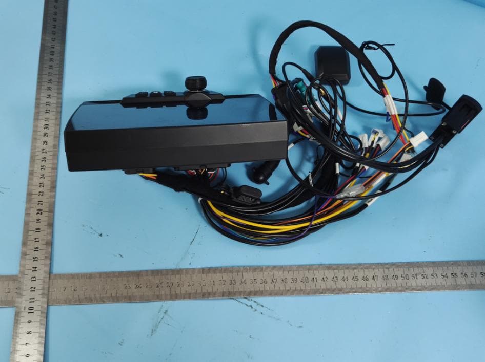
Model No.: GMR-7V1 Page 1 of 5 INTERNAL PHOTO OF SAMPLE INTERNAL PHOTO OF SAMPLE PCB Antenna Location Model No.: GMR-7V1 Page 2 of 5 INTERNAL PHOTO OF SAMPLE PCB INTERNAL PHOTO OF SAMPLE PCB Model No.: GMR-7V1 Page 3 of 5 INTERNAL PHOTO OF SAMPLE PCB INTERNAL PHOTO OF SAMPLE PCB Model No.: GMR-7V1 Page 4 of 5 INTERNAL PHOTO OF SAMPLE PCB INTERNAL PHOTO OF SAMPLE PCB Model No.: GMR-7V1 Page 5 of 5 INTERNAL PHOTO OF SAMPLE PCB
RF Exposure Info
Shenzhen Most Technology Service Co., Ltd. No.5, 2nd Langshan Road, North District, Hi-tech Industrial Park, Nanshan, Shenzhen, Guangdong, China. RF Exposure Evaluation Report Report Reference No. ..................... : FCC ID.. .......................................... : MTEB22111697-H 2AG9Y-GMR-7V1 Compiled by ( position+printed name+signature) .. : File administrators Alisa Luo Supervised by ( position+printed name+signature) .. : Test Engineer Sunny Deng Approved by ( position+printed name+signature) .. : Manager Yvette Zhou Date of issue ..................................... : December 01,2022 Representative Laboratory Name .: Shenzhen Most Technology Service Co., Ltd. Address ............................................ : No.5, 2nd Langshan Road, North District, Hi-tech Industrial Park, Nanshan, Shenzhen, Guangdong, China. Applicant’s name ............................ : MAXXSONICS USA INC Address ............................................ : 851 E. Park Avenue, Libertyville, Illinois, United States, 60048 Test specification/ Standard ..........: 47 CFR Part 1.1307 47 CFR Part 1.1310 KDB447498D01 General RF Exposure Guidance v06 TRF Originator .................................. : Shenzhen Most Technology Service Co., Ltd. Shenzhen Most Technology Service Co., Ltd. All rights reserved. This publication may be reproduced in whole or in part for non-commercial purposes as long as the Shenzhen Most Technology Service Co., Ltd. is acknowledged as copyright owner and source of the material. Shenzhen Most Technology Service Co., Ltd. takes no responsibility for and will not assume liability for damages resulting from the reader's interpretation of the reproduced material due to its placement and context. Test item description ..................... : MARINE & POWERSPORTS Trade Mark ....................................... : MBQUART Manufacturer .................................... : MAXXSONICS USA INC Model/Type reference....................... : GMR-7V1 Listed Models .................................. : GMR-7CFM Modulation Type ............................... : GFSK, π/4DQPSK, 8DPSK Operation Frequency ........................ : From 2402MHz to 2480MHz Hardware Version .............................. MRC7 MB PCB VER:B Software Version ............................... MRC7-CTP1024X600-MB-V1.18 Rating ................................................ DC 12V Result................................................ : PASS Report No.: MTEB22111697-H Page 2 of 5 T E S T R E P O R T Equipment under Test : MARINE & POWERSPORTS Model /Type : GMR-7V1 Listed Models : GMR-7CFM Remark Only the model name is different. Applicant : MAXXSONICS USA INC Address : 851 E. Park Avenue, Libertyville, Illinois, United States, 60048 Manufacturer : MAXXSONICS USA INC Address : 851 E. Park Avenue, Libertyville, Illinois, United States, 60048 Test Result: PASS The test report merely corresponds to the test sample. It is not permitted to copy extracts of these test result without the written permission of the test laboratory. Report No.: MTEB22111697-H Page 3 of 5 1. Revision History Revision Issue Date Revisions Revised By 00 2022.12.01 Initial Issue Alisa Luo Report No.: MTEB22111697-H Page 4 of 5 2. SAR Evaluation 2.1 RF Exposure Compliance Requirement 2.1.1 Standard Requirement According to §1.1307(e)(1), systems operating under the provisions of this section shall be operated in a manner that ensures that the public is not exposed to radio frequency energy level in excess of the Commission’s guidelines. According to §1.1310 and §2.1091 RF exposure is calculated. KDB447498 D01: Mobile and Portable Devices RF Exposure Procedures and Equipment Authorization Policies 2.1.2 Limits F= Frequency in MHz Friis Formula Friis transmission formula: Pd = (Pout*G)/(4* Pi * R 2) Where Pd = power density in mW/cm2 Pout = output power to antenna in mW G = gain of antenna in linear scale Pi = 3.1416 R = distance between observation point and center of the radiator in cm Pd id the limit of MPE, 1 mW/cm2 . If we know the maximum gain of the antenna and the total power input to the antenna, through the calculation, we will know the distance r where the MPE limit is reached. Report No.: MTEB22111697-H Page 5 of 5 2.1.3 EUT RF Exposure Antenna Gain: -2dBi Antenna Gain: The maximum Gain measured in fully anechoic chamber is 2.4 in linear scale. Output Power Into Antenna & RF Exposure Evaluation Distance: BT classic GFSK Test channel Peak Output Power (dBm) Tune up tolerance (dBm) Maximum tune-up Power (dBm) Lowest(2402MHz) -0.710 -0.710±1 0.290 Middle(2441MHz) -0.221 -0.221±1 0.779 Highest(2480MHz) -0.130 -0.130±1 0.870 π/4DQPSK Test channel Peak Output Power (dBm) Tune up tolerance (dBm) Maximum tune-up Power (dBm) Lowest(2402MHz) -0.169 -0.169±1 0.831 Middle(2441MHz) 0.360 0.360±1 1.360 Highest(2480MHz) 0.456 0.456±1 1.456 8DPSK Test channel Peak Output Power (dBm) Tune up tolerance (dBm) Maximum tune-up Power (dBm) Lowest(2402MHz) 0.181 0.181±1 1.181 Middle(2441MHz) 0.669 0.669±1 1.669 Highest(2480MHz) 0.718 0.718±1 1.718 BT classic Worst case: 8DPSK Channel Maximum Peak Conducted Output Power (dBm) Maximum Peak Conducted Output Power (MW) Antenna Gain (dBi) Powe r Density at R = 20 cm (mW/cm2) Limit Result Highest(2480MHz) 1.718 1.48 -2 0.0001 1.0 Pass Note: 1) Refer to report MTEB22111697-R for EUT test Max Conducted average Output Power value. Note: 2) Pd = (Pout*G)/(4* Pi * R2)=(1.48*0.63)/(4*3.1416*20 2 )=0.0001 Note: 3) EUT's Bluetooth module is more than 20cm away from the human body.. .......................THE END OF REPORT.........................
Test Report
Inverted F Antenna Specification Summary ITEM ANT SPEC Model Name BT ANT MAX. Gain -2dB Manufacture Maxxsonics Address 851 E Park Avenue Libertyville, IL 60048 Antenna Photo
Test Report
Shenzhen Most Technology Service Co., Ltd. No.5, 2nd Langshan Road, North District, Hi-tech Industrial Park, Nanshan, Shenzhen, Guangdong, China. TEST REPORT FCC Rules Part 15.247 Report Reference No. .....................: FCC ID.. .......................................... : MTEB22111697-R 2AG9Y-GMR-7V1 Compiled by ( position+printed name+signature) .. : File administrators Alisa Luo Supervised by ( position+printed name+signature) .. : Test Engineer Sunny Deng Approved by ( position+printed name+signature) .. : Manager Yvette Zhou Date of issue ..................................... : December 01,2022 Representative Laboratory Name .: Shenzhen Most Technology Service Co., Ltd. Address ............................................ : No.5, 2nd Langshan Road, North District, Hi-tech Industrial Park, Nanshan, Shenzhen, Guangdong, China. Applicant’s name ............................ : MAXXSONICS USA INC Address ............................................ : 851 E. Park Avenue, Libertyville, Illinois, United States, 60048 Test specification/ Standard ..........: FCC Rules Part 15.247 TRF Originator .................................. : Shenzhen Most Technology Service Co., Ltd. Shenzhen Most Technology Service Co., Ltd. All rights reserved. This publication may be reproduced in whole or in part for non-commercial purposes as long as the Shenzhen Most Technology Service Co., Ltd. is acknowledged as copyright owner and source of the material. Shenzhen Most Technology Service Co., Ltd. takes no responsibility for and will not assume liability for damages resulting from the reader's interpretation of the reproduced material due to its placement and context. Test item description ..................... : MARINE & POWERSPORTS Trade Mark ....................................... : MBQUART Manufacturer .................................... : MAXXSONICS USA INC Model/Type reference....................... : GMR-7V1 Listed Models .................................. : GMR-7CFM Modulation Type ............................... : GFSK, π/4DQPSK, 8DPSK Operation Frequency ........................ : From 2402MHz to 2480MHz Hardware Version .............................. MRC7 MB PCB VER:B Software Version ............................... MRC7-CTP1024X600-MB-V1.18 Rating ................................................ DC 12V Result................................................ : PASS Report No.: MTEB22111697-R Page 2 of 40 T E S T R E P O R T Equipment under Test : MARINE & POWERSPORTS Model /Type : GMR-7V1 Listed Models : GMR-7CFM Remark Only the model name is different. Applicant : MAXXSONICS USA INC Address : 851 E. Park Avenue, Libertyville, Illinois, United States, 60048 Manufacturer : MAXXSONICS USA INC Address : 851 E. Park Avenue, Libertyville, Illinois, United States, 60048 Test Result: PASS The test report merely corresponds to the test sample. It is not permitted to copy extracts of these test result without the written permission of the test laboratory. Report No.: MTEB22111697-R Page 3 of 40 Contents 1 REVISION HISTORY ................................................................ 4 2 TEST STANDARDS .................................................................. 5 3 SUMMARY ............................................................................. 6 3.1 General Remarks 6 3.2 Product Description 6 3.3 Equipment Under Test 6 3.4 Short description of the Equipment under Test (EUT) 6 3.5 EUT operation mode 7 3.6 Block Diagram of Test Setup 7 3.7 Test Item (Equipment Under Test) Description* 7 3.8 Auxiliary Equipment (AE) Description 7 3.9 Antenna Information* 7 3.10 Related Submittal(s) / Grant (s) 8 3.11 Modifications 8 4 TEST ENVIRONMENT ............................................................... 9 4.1 Address of the test laboratory 9 4.2 Environmental conditions 9 4.3 Summary of measurement results 10 4.4 Statement of the measurement uncertainty 10 4.5 Equipments Used during the Test 11 5 TEST CONDITIONS AND RESULTS ............................................ 12 5.1 AC Power Conducted Emission 12 5.2 Radiated Emission 13 5.3 Maximum Peak Output Power 19 5.4 20dB Bandwidth 20 5.5 Frequency Separation 23 5.6 Number of hopping frequency 26 5.7 Time of Occupancy (Dwell Time) 28 5.8 Spurious RF Conducted Emission 31 5.9 Pseudorandom Frequency Hopping Sequence 37 5.10 Antenna Requirement 38 6 TEST SETUP PHOTOS OF THE EUT .......................................... 39 7 PHOTOS OF THE EUT ............................................................. 40 Report No.: MTEB22111697-R Page 4 of 40 1 Revision History Revision Issue Date Revisions Revised By 00 2022-12-01 Initial Issue Alisa Luo Report No.: MTEB22111697-R Page 5 of 40 2 TEST STANDARDS The tests were performed according to following standards: FCC Rules Part 15.247 : Frequency Hopping, Direct Spread Spectrum and Hybrid Systems that are in operation within the bands of 902-928 MHz, 2400-2483.5 MHz, and 5725-5850 MHz. ANSI C63.10-2013 : American National Standard for Testing Unlicensed Wireless Devices Report No.: MTEB22111697-R Page 6 of 40 3 SUMMARY 3.1 General Remarks Date of receipt of test sample : 2022.11.22 Testing commenced on : 2022.11.23 Testing concluded on : 2022.11.29 3.2 Product Description Product Name: MARINE & POWERSPORTS Model/Type reference: GMR-7V1 Power Supply: DC12V Testing sample ID: MT22110199 Bluetooth : Supported Type: Bluetooth BR/EDR Modulation: GFSK, π/4DQPSK, 8DPSK Operation frequency: 2402MHz~2480MHz Channel number: 79 Channel separation: 1MHz Antenna type: PCB antenna Antenna gain: -2 dBi 3.3 Equipment Under Test Power supply system utilised Power supply voltage : ○ 230V / 50 Hz ○ 120V / 60Hz ● 12 V DC ○ 24 V DC ○ Other (specified in blank below) 3.4 Short description of the Equipment under Test (EUT) This is a MARINE & POWERSPORTS For more details, refer to the user’s manual of the EUT. Report No.: MTEB22111697-R Page 7 of 40 3.5 EUT operation mode The Applicant provides communication tools software(Engineer mod…
Text truncated - open the document above for the full version.
Test Setup Photos
Model No.: GMR-7V1 RE TEST SETUP RE TEST SETUP
Contact Information
Applicant
Brian Sherman(Director of Business Development)
Technical Contact
Shenzhen Most Technology Service Co.,Ltd.Mark Wen
[email protected]86-755-86170306
No.5, 2nd Langshan Road, North District, · Shenzhen, Guangdong · China
Test Firm
Shenzhen Most Technology Service Co., Ltd.Sunny Deng
[email protected]0755-26980487
Technical Specifications
| # | Rule Parts | Frequency Range | Power Output |
|---|---|---|---|
| 1 | 15C | 2.40 GHz - 2.48 GHz | 1.18 mW |
Other Applications from MAXXSONICS USA INC
2AG9Y-25041-003
Jul 10, 2024MARINE & POWERSPORTS
Equipment Class
DSS - Part 15 Spread Spectrum Transmitter