2AGCCAEH-W4G2WIFI Module
Hisense (Guangdong) Air Conditioning Co., Ltd.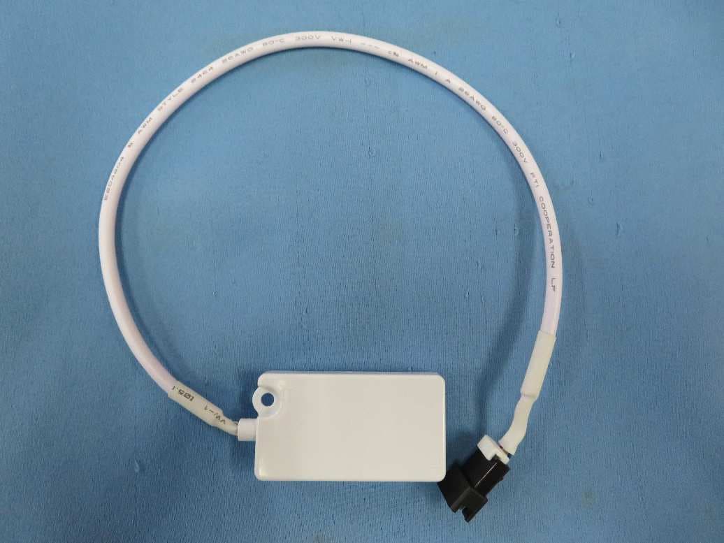
Click to zoom
Application Details
- Equipment Class
- DTS - Digital Transmission System
- Date of Grant
- Jun 06, 2021
- Application Purpose
- Original Equipment
- Date of Application
- Jun 06, 2021
- Equipment Note
- WIFI Module
- Frequency Range
- 2412.00000000 - 2462.00000000
- Country
- China
Documents & Files
Document Text
Text extracted from the exhibit documents filed with the FCC. Open a document above to read the original.
Users Manual
AEH-W4G2 Specification 1: General Description The wireless module complies with IEEE 802.11 b/g/n standard and it can achieve up to a speed of 150Mbps with single stream in 802.11n draft 7.0, 54Mbps as specified in IEEE 802.11g, or 11Mbps for IEEE 802.11b to connect to the wireless LAN. This compact module is a total solution for a combination of Wi-Fi 802.11b/g/n technologies with Microcontroller Processor. The module is specifically developed for embedded system devices. 2: Module Hardware Overview 2.1 Block Diagram The general Hardware architecture is shown below Figure: IC:RTL8710BL IC1001 125Mhz UM3352EESA RS485 IC2001 DC-DC converter 3.3V IC2002 Antenna 2.4GHz~2.5GHz WIFI MODEL Home Appliance Block Diagram GD25Q80CTIG Flash Memo ry 104Mhz IC2003 3.3V 5V Control Oscillator=40Mhz 2.2 Feature ◆ Single-band 2.4GHz IEEE 802.11b/g/n ◆ Combines an ARM CM4 MCU,WLAN MAC,a 1T1R capable WLAN baseband,and RF in a single chip. ◆ Lead-Free / RoHS ◆ Single power supply voltage 5V 1.3 Interface ◆ Interface ■ JST-4 connector ◆ Pin definition 4 32 1 Pin number Pin name Pin description 1 5V 5.0V Power 2 RS485A+ Communication line positive 3 RS485B- Communication line nagetive 4 GND Ground pad 3.WiFI RF Specification RF Specification Feature Description Feature Description WLAN Standard IEEE 802.11b/g/n(HT20/HT40), WiFi compliant Frequency Range 2.412GHz~2.462GHz for FCC and ICES 2.412GHz~2.472GHz for Europe. Number of Channels CH1~CH11 for FCC and ICES, Shield 12,13 Channels with Software. CH1~CH13 for Europe. Modulation 802.11b : CCK, DQPSK, DBPSK 802.11 g/n : OFDM /64-QAM,16-QAM, QPSK, BPSK Output Power ≤12dBm for FCC And ICES ≤19dBm for Europe Data Rate 802.11b : 1, 2, 5.5, 11Mbps 802.11g : 6, 9, 12, 18, 24, 36, 48, 54Mbps 802.11n(HT20): 6.5, 13, 19.5, 26, 39, 52, 58.5, 65,72.2Mbps 802.11n(HT40): up to 150Mbps Antenna Reference Internal Printed ANT :Small antennas with 1.0 dBi peak gain 4. Mechanical Specifications PCB Assembly Dimension: ◆ Dimension (L x W) : L:40.0mm*W:20.0mm 5.Requirement of FCC KDB 996369 D03 for module certification: 5.1 List of applicable FCC rules and Canada rules: The module complies with FCC Part 15.247, and Canada RSS-247. 5.2 Summarize the specific operational use conditions: The module has been certified for Fix/Mobile applications. The host product operating conditions must be such that there is a minimum separation distance of 20 cm (or possibly greater than 20 cm) between the antenna radiating structures and nearby persons. The host manufacturer is obligated to confirm the use conditions of the host product to ensure that distance specified in the instructions is met. In this case the host product is classified as either a mobile device or a fixed device for RF exposure purposes. This transmitter must not be co-located or operating in conjunction with any other antenna or transmitter. 5.3 Limited module procedures: Not applicable. 5.4 Trace antenna designs: Not applicable. 5.5 RF exposure considerations: This equipment complies with FCC’s and IC’s RF radiation exposure limits set forth for an uncontrolled environment. The antenna(s) used for this transmitter must be installed and operated to provide a separation distance of at least 20 cm from all persons and must not be collocated or operating in conjunction with any other antenna or transmitter. Installers must ensure that 20cm separation distance will be maintained between the device and users. DÉCLARATION D’IC SUR L’EXPOSITION AUX RADIATIONS: Cet appareil est conforme aux limites d’exposition au rayonnement RF stipulées par la FCC et l’IC pour une utilisation dans un environnement non contrôlé. Les antennes utilisées pour cet émetteur doivent être installées et doivent fonctionner à au moins 20 cm de distance des utilisateurs et ne doivent pas être placées près d’autres antennes ou émetteurs ou fonctionner avec ceux-ci. Les installateurs doivent s’assurer qu’une distance de 20 cm sépare l’appareil des utilisateurs. Note: the OEM product manuals must include a statement in order to alert the users of FCC RF exposure compliance. 5.6 Antennas: Type Gain Impedance Application Min Separation PCB type Antenna 1.0 dBi 50Ω Fixed 20 cm The antenna is permanently attached, can’t be replaced. 5.7 Label and compliance information: This device complies with part 15 of the FCC rules. Operation is subject to the following two conditions: (1) this device may not cause harmful interference, and (2) this device must accept any interference received, including interference that may cause undesired operation. NOTE: The manufacturer is not responsible for any radio or TV interference caused by unauthorized modifications or changes to this equipment. Such modifications or changes could void the user’s authority to operate the equipment. Warning: Changes or modifications to this unit not expressly approved by the party responsible for compliance could void the user’s authority to operate the equipment. NOTE: This equipment has been tested and found to comply with the limits for a Class B digital device, pursuant to part 15 of the FCC Rules. These limits are designed to provide reasonable protection against harmful interference in a residential installation. This equipment generates uses and can radiate radio frequency energy and, if not installed and used in accordance with the instructions, may cause harmful interference to radio communications. However, there is no guarantee that interference will not occur in a particular installation. If this equipment does cause harmful interference to radio or television reception, which can be determined by turning the equipment off and on, the user is encouraged to try to correct the interference by one or more of the following measures: - Reorient or relocate the receiving antenna. - Increase the separation between the equipment and receiver. ‐Connect the equipment into an outlet on a circuit different from that to which the receiver is connected. ‐Consult the dealer or an experienced radio/T…
Text truncated - open the document above for the full version.
Cover Letter(s)
Modular Approval Request Letter Hisense (Guangdong) Air Conditioning Co., Ltd. +86 0757 7503998459 No.8 Hisense Road, Advanced Manufacturing Jiangsha Demonstration Park, Jiangmen City, Guangdong Province, P. R. China Product Name: WiFi module Model Number: AEH-W4G2 FCC ID:2AGCCAEH-W4G2 Date: 2021-04-19 Requirement of Public Notice DA00‐1407 / part 15.212 1. The modular transmitter must have its own RF shielding. Yes. The module has its own RF shielding. 2. The modular transmitter must have buffered modulation/data inputs. Yes This module is not only used in our own specific products but also for OEM market. We have total control of the design and the data protocol through IC Chip “IC1001 RTL8710BL”. The radio IC we use complies with FCC part 15. 3. The modular transmitter must have its own power supply regulation. Yes This module is not only used in our own specific products but also for OEM market, this module has its own voltage regular (IC2002). The radio IC complies with FCC part 15. 4. The modular transmitter must comply with the antenna requirements of Section 15.203 and 15.204(c). Yes The antenna is a PCB antenna which is permanently attached. 5. The modular transmitter must be tested in a stand‐alone configuration, i.e., the module must not be inside another device during testing. Yes This module has been tested in a stone-alone configuration as shown in the test setup photos. 6. The modular transmitter must be labeled with its own FCC ID number, and, if the FCC ID is not visible when the module is installed inside another device, then the outside of the device into which the module is installed must also display a label referring to the enclosed module. Yes This module will be labelled with its FCC ID number. When the module is installed in our products and it is not visible, an external label will be applied which refer to the modules FCC ID number inside. 7. The modular transmitter must comply with any specific rule or operating requirements applicable to the transmitter and the manufacturer must provide adequate instructions along with the Yes This module is not only used in our own specific products but also for OEM market. The user manuals are based on the requirement specifications. module to explain any such requirements. A copy of these instructions must be included in the application for equipment authorization. 8. The modular transmitter must comply with any applicable RF exposure requirements. For example, FCC Rules in Sections 2.1091, 2.1093 and specific Sections of Part 15, including 15.319(i), 15.407(f), 15.253(f) and 15.255(g), require that Unlicensed PCS, UNII and millimeter wave devices perform routine Environmental evaluation for RF Exposure to demonstrate compliance. In addition spread spectrum transmitters operating under Section 15.247 are required to address RF Exposure compliance in accordance with Section 15.247(b)(4). Yes The module is instructed the user to install the host with more than 20cm from the user. This module is not only used in our own specific products but also for OEM market.. And the RF exposure we have prepared. Thank you. Sincerely, Peng ting 2021-04-19
Cover Letter(s)
1(1) Hisense (Guangdong) Air Conditioning Co., Ltd. 1 March 2021 Attention: Application Examiner RE: Request for Confidentiality Applicant: Hisense (Guangdong) Air Conditioning Co., Ltd. FCC ID: 2AGCCAEH-W4G2 To Whom It May Concern: Permanent Confidentiality Request is hereby submitted by Hisense (Guangdong) Air Conditioning Co., Ltd. to withhold permanently from public review certain portions of the application for equipment certification for the referenced FCC identifiers. This request for confidentiality is made pursuant to 47 CFR 0.457(d) and 0.459 of the FCC Rules. In particular, the following sections of the application are to be kept permanently confidential: • Schematics • Detailed Block Diagrams • Detailed Operational/Functional Description Rationale for request for confidentiality: Hisense (Guangdong) Air Conditioning Co., Ltd. has invested considerable time and materials in research and development to produce the referenced product. [Permanent confidentiality: Disclosure of the permanently confidential portions of this application to competitors would not only give them significant competitive advantages in developing similar products, but would also disclose successful implementation of unpublished, leading edge technology developed by us.] [Short term confidentiality: Disclosure of the short- term confidential portions of this application during the period of importation and/or distribution would reveal key aspects of proprietary technology to competitors and diminish the value of our investment in research and development.] For FCC certification; delete for TCB certification: The fee for confidentiality has been submitted along with the fee for certification. If you have questions or need further information, please contact the undersigned. Sincerely, Signature Peng ting Certification Engineer Hisense (Guangdong) Air Conditioning Co., Ltd.
External Photos
External Photos
ID Label/Location Info
Label L=40mm,W=20mm Front view Label location
Internal Photos
Internal Photos
RF Exposure Info
Intertek Testing Services Shenzhen Ltd. Guangzhou Branch Room 02, & 101/E201/E301/E401/E501/E601/E701/E801 of Room 01 1-8/F., No. 7-2. Caipin Road, Science City, GETDD, Guangzhou, Guangdong, China Report No.: 210107026GZU-002 FCC ID: 2AGCCAEH-W4G2 Version: 08 July 2020 Page 1 of 2 FCC RF Exposure-Mobile (MPE) RF Exposure Compliance Requirement Model no.: AEH-W4G2 1. Standard requirement Systems operating under the provisions of this section shall be operated in a manner that ensures that the public is not exposed to radio frequency energy level in excess limit for maximum permissible exposure. In accordance with 47 CFR FCC Part 2 Subpart J, section 2.1091 this device has been defined as a mobile device whereby a distance of 0.2m normally can be maintained between the user and the device. (a) Limits for Occupational / Controlled Exposure Frequency Range (MHz) Electric Field Strength (E) (V/m) Magnetic Field Strength (H) (A/m) Power Density (S)(mW/cm 2 ) Averaging Times ׀E׀ 2 ׀, H׀ 2 or S (minutes) 0.3-3.0 614 1.63 (100)* 6 3.0-30 1842/f 4.89/f (900/f)* 6 30-300 61.4 0.163 1.0 6 300-1500 -- -- F/300 6 1500-100000 -- -- 5 6 (b) Limits for General Population / Uncontrolled Exposure Frequency Range (MHz) Electric Field Strength (E) (V/m) Magnetic Field Strength (H) (A/m) Power Density (S)(mW/cm 2 ) Averaging Times ׀E׀ 2 ׀, H׀ 2 or S (minutes) 0.3-1.34 614 1.63 (100)* 30 1.34-30 824/f 2.19/f (180/f)* 30 30-300 27.5 0.073 0.2 30 300-1500 -- -- F/1500 30 1500-100000 -- -- 1.0 30 Note: f=frequency in MHz; *Plane-wave equivalent power density Intertek Testing Services Shenzhen Ltd. Guangzhou Branch Room 02, & 101/E201/E301/E401/E501/E601/E701/E801 of Room 01 1-8/F., No. 7-2. Caipin Road, Science City, GETDD, Guangzhou, Guangdong, China Report No.: 210107026GZU-002 FCC ID: 2AGCCAEH-W4G2 Version: 08 July 2020 Page 2 of 2 FCC RF Exposure-Mobile (MPE) 2. MPE Calculation Method E (V/m)=(30*P*G) 0.5 /d Power Density: Pd(W/m 2 )=E 2 /377 E=Electric Field (V/m) P=Peak RF output Power (W) G=EUT Antenna numeric gain (numeric) d= Separation distance between radiator and human body (m) The formula can be changed to Pd= (30*P*G)/(377*d 2 ) From the peak EUT RF output power, the minimum mobile separation distance, d=0.2m, as well as the gain of the used antenna, the RF power density can be obtained. 3. Calculated Result and Limit Frequency (MHz) Antenna Gain (dBi) Antenna Gain (Numeric) Maximum Output Power (dBm) Maximum Peak Output Power (mW) Power Density (S) (mW/cm 2 ) Limit of Power Density (S) (mW/cm 2 ) Test Result 2412-2462 1.0 1.26 12 15.85 0.00397 1 Complies Remark: The antenna gain and maximum output power were declared by applicant. Test Location: Intertek Testing Services Shenzhen Ltd. Guangzhou Branch All tests were performed at: Room102/104, No 203, KeZhu Road, Science City, GETDD Guangzhou, China
Test Report
Hisense (Guangdong) Air Conditioning Co., Ltd . TEST REPORT SCOPE OF WORK EMC TESTING–AEH-W4G2 REPORT NUMBER 210107026GZU-001 ISSUE DATE [REVISED DATE] 31 May 2021 [---------------------] PAGES 88 DOCUMENT CONTROL NUMBER FCC WIFI-d © 2017 INTERTEK TEST REPORT Room 02, & 101/E201/E301/ E401/E501/E601/E701/E801 of Room 01 1-8/F., No. 7-2. Caipin Road, Science City, GETDD, Guangzhou, Guangdong, China Telephone: +86 20 8213 9688 Facsimile: +86 20 3205 7538 www.intertek.com.cn This report is for the exclusive use of Intertek's Client and is provided pursuant to the agreement between Intertek and its Client. Intertek's responsibility and liability are limited to the terms and conditions of the agreement. Intertek assumes no liability to any party, other than to the Client in accordance with the agreement, for any loss, expense or damage occasioned by the use of this report. Only the Client is authorized to permit copying or distribution of this report and then only in its entirety. Any use of the Intertek name or one of its marks for the sale or advertisement of the tested material, product or service must first be approved in writing by Intertek. The observations and test results in this report are relevant only to the sample tested. This report by itself does not imply that the material, product, or service is or has ever been under an Intertek certification program. Intertek Testing Services Shenzhen Ltd. Guangzhou Branch Room 02, & 101/E201/E301/E401/E501/E601/E701/E801 of Room 01 1-8/F., No. 7-2. Caipin Road, Science City, GETDD, Guangzhou, Guangdong, China Version: 10 June 2019 Page 2 of 88 FCC WIFI-d Applicant Name & Address : Hisense (Guangdong) Air Conditioning Co., Ltd. No.8 Hisense Road, Advanced Manufacturing Jiangsha Demonstration Park, Jiangmen City, Guangdong Province, P. R. China Manufacturing Site : Same as applicant Intertek Report No: FCC ID: : 210107026GZU-001 2AGCCAEH-W4G2 Test standards 47 CFR PART 15 Subpart C: 2019 section 15.247 Sample Description Product : WIFI Module Model No. : AEH-W4G2 Electrical Rating : 5Vdc, 0.45A Serial No. : Not Labeled Date Received : 07 January 2021 Date Test Conducted : 12 January 2021 to 20 March 2021 Prepared and Checked By Dean Liu Project Engineer Approved By: Strong Yao Manager TEST REPORT Intertek Report No.: 210107026GZU-001 Version: 10 June 2019 Page 3 of 88 FCC WIFI-d CONTENT TEST REPORT ........................................................................................................................... 1 CONTENT ............................................................................................................................. 3 1.0 TEST RESULT SUMMARY ............................................................................................ 4 2.0 GENERAL DESCRIPTION .............................................................................................. 5 2.1 PRODUCT DESCRIPTION ........................................................................................................ 5 2.2 RELATED SUBMITTAL(S) GRANTS ............................................................................................ 6 2.3 TEST METHODOLOGY ........................................................................................................... 6 2.4 TEST FACILITY ...................................................................................................................... 6 3.0 SYSTEM TEST CONFIGURATION .................................................................................. 6 3.1 JUSTIFICATION ..................................................................................................................... 6 3.2 EUT EXERCISING SOFTWARE.................................................................................................. 7 3.3 SPECIAL ACCESSORIES ........................................................................................................... 8 3.4 MEASUREMENT UNCERTAINTY ............................................................................................... 8 3.5 EQUIPMENT MODIFICATION .................................................................................................. 8 3.6 SUPPORT EQUIPMENT LIST AND DESCRIPTION .......................................................................... 9 4.0 MEASUREMENT RESULTS ......................................................................................... 10 4.1 ANTENNA REQUIREMENT .................................................................................................... 10 4.2 6 DB BANDWIDTH (DTS BANDWIDTH) .................................................................................. 11 4.4 DUTY CYCLE ...................................................................................................................... 19 4.3 MAXIMUM AVERAGE CONDUCTED OUTPUT POWER ................................................................ 23 4.5 PEAK POWER SPECTRAL DENSITY .......................................................................................... 25 4.6 OUT OF BAND CONDUCTED EMISSIONS ................................................................................. 33 4.7 OUT OF BAND RADIATED EMISSIONS .................................................................................... 43 4.8 RADIATED EMISSIONS IN RESTRICTED BANDS .......................................................................... 43 4.9 BAND EDGES REQUIREMENT ................................................................................................ 78 4.9 CONDUCTED EMISSION TEST ................................................................................................ 84 5.0 TEST EQUIPMENT LIST ............................................................................................. 87 TEST REPORT Intertek Report No.: 210107026GZU-001 Version: 10 June 2019 Page 4 of 88 FCC WIFI-d 1.0 TEST RESULT SUMMARY Test Item Test Requirement Test Method Result Antenna Requirement FCC PART 15 C section 15.247…
Text truncated - open the document above for the full version.
Test Setup Photos
AC conducted Emission Radiated Emission (30MHz-1GHz) Radiated Emission (Above 1GHz) Remark: The EUT is center on the turntable, due to the edge of desk placed on the diameter of the turntable.
Contact Information
Applicant
Peng Ting(Certification Engineer)
Technical Contact
Intertek Testing Services Shenzhen Ltd.,GuangzhouDean Liu
[email protected]020-82139657
Room102/104 · Guangzhou · China
Non-Technical Contact
Intertek Testing Services Shenzhen Ltd.,GuangzhouDean Liu
[email protected]020-82139657
Test Firm
Intertek Testing Services Shenzhen LTD., GuangzhouEmily Huang
[email protected]+86 21 50319089-232
Technical Specifications
| # | Rule Parts | Frequency Range | Power Output |
|---|---|---|---|
| 1 | 15C | 2.41 GHz - 2.46 GHz | 13.58 mW |