2AGDY-SHFT1SHFT
SHFT ApS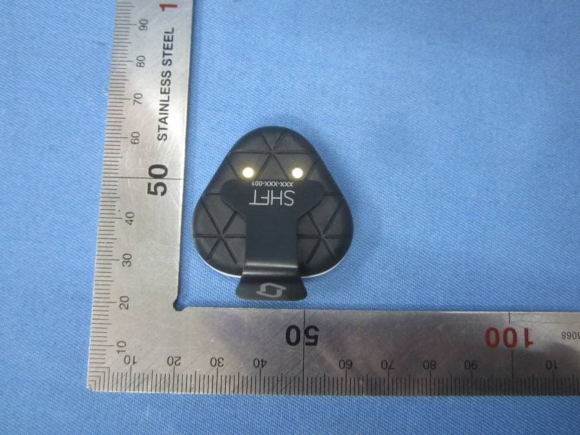
Click to zoom
Application Details
- Equipment Class
- DXX - Part 15 Low Power Communication Device Transmitter
- Date of Grant
- Nov 23, 2015
- Application Purpose
- Original Equipment
- Date of Application
- Nov 23, 2015
- Equipment Note
- SHFT
- Frequency Range
- 2402.00000000 - 2480.00000000
- Company
- SHFT ApS
- Country
- Denmark
Documents & Files
Document Text
Text extracted from the exhibit documents filed with the FCC. Open a document above to read the original.
Users Manual
SHFT APS, ITU, RUED LANGGAARDS VEJ 7, DK-2300 COPENHAGEN S 1 SHFT User Guide Step 1 – Charging the PODs The PODs are a special version, which does not need turning on or off. POD blink patterns: - Charging: Constant red light with high intensity. - Connected: Red blink with high intensity every 1 second. - Not connected: Red blink with low intensity every 2 seconds. The POD charger must be placed in a USB outlet. A full charge takes two hours. When a POD is fully charged, it will run for at least 6 hours. Step 2 – Placing the Pods Place the Foot Pod on your right Foot and the Chest Pod on the Chest Strap as shown on the picture: Step 3 – Using the APP The app is started from the home screen by clicking on the SHFT icon. When the app is loaded there are 3 options. - Just Run - Reports - Settings Click on Just Run and the APP will search for and connect to the two Pods. You are now ready for your run. Click on Start Run. SHFT APS, ITU, RUED LANGGAARDS VEJ 7, DK-2300 COPENHAGEN S 2 Click on Stop, when you end your run. After a run is stopped, you will be presented with a report describing the run you just did. Here you can see detailed info about your running, as well as charts for each metric. The charts can be found by clicking on one of the categories in the Triad and then clicking on one of the metrics. The report button will by default show you the report of your last run. From the report screen, it's possible to navigate to an older report by clicking on the Calendar icon at the top right corner. By clicking on the other Icon in the top right hand corner, you can see all messages from the coach. Your run course is displayed at the bottom of the report screen. On the left side of the Triad, there is an icon of a person running. By clicking this icon, you will be presented with a 3D Animation. On the right hand side of the Triad, there is a “Doctor’s” symbol describing your run from a medical stand point. At the bottom of the Triad, there are 1-3 Technical Drills as suggestions to how to improve your run even more. Under settings, the following elements can be configured: Name: Your name, which will personalize the experience with SHFT Metric: This setting is for manipulating your current focus. SHFT will by default handle this by itself based on your running performance during each run. Demo: This setting enables/disables demo mode. When in demo mode, a simulated run will be played when starting “JustRun” Reset: This button resets your current progression Logout: Log out the current active user Terminate: Use if you experience unexpected behavior with SHFT, primarily with the Pod connectivity. This will close SHFT and turn off Bluetooth. Enjoy running with SHFT ! SHFT APS, ITU, RUED LANGGAARDS VEJ 7, DK-2300 COPENHAGEN S 3 FCC Statement This equipment has been tested and found to comply with the limits for a Class B digital device, pursuant to Part 15 of the FCC Rules. These limits are designed to provide reasonable protection against harmful interference in a residential installation. This equipment generates uses and can radiate radio frequency energy and, if not installed and used in accordance with the instructions, may cause harmful interference to radio communications. However, there is no guarantee that interference will not occur in a particular installation. If this equipment does cause harmful interference to radio or television reception, which can be determined by turning the equipment off and on, the user is encouraged to try to correct the interference by one or more of the following measures: -- Reorient or relocate the receiving antenna. -- Increase the separation between the equipment and receiver. -- Connect the equipment into an outlet on a circuit different from that to which the receiver is connected. -- Consult the dealer or an experienced radio/TV technician for help. Changes or modifications not expressly approved by the party responsible for compliance could void the user's authority to operate the equipment. This device complies with part 15 of the FCC Rules. Operation is subject to the following two conditions: (1) This device may not cause harmful interference, and (2) this device must accept any interference received, including interference that may cause undesired operation. IC STATEMENT This device complies with Industry Canada’s licence- exempt RSSs. Operation is subject to the following two conditions: (1) This device may not cause interference; and (2) This device must accept any interference, including interference that may cause undesired o peration of the device. Le présent appareil est conforme aux CNR d'Industrie Canada applicables aux appareils radio ex empts de licence. L'exploitation est autorisée aux deux conditions suivantes : (1) l'appareil ne d oit pas produire de brouillage, et (2) l'utilisateur de l'appareil doit accepter tout brouillage radio électrique subi, même si le brouillage est susceptible d'en compromettre le fonctionnement.
Cover Letter(s)
SHFT ApS IT-University Rued Langgards Vej 7 2300 Copenhagen S, Denmark 2015-11-02 Equipment Autorisation Division Federal Communications Commission 7435 Oakland Mills Road Columbia, MD 21046 FCC ID: 2AGDY-SHFT1 Product Name: SHFT Request for Confidentiality Pursuant to Sections 0.457 and 0.459 of the commissions rules, we hereby request that the following documents be held confidential: Schematics Block diagram Operational Description These materials contain trade secrets and proprietary information and are not customarily released to the public. The public disclosure of this information might be harmful to the company and provide unjustified benefits to our competitors. Dated this 11/02/2015 By: Tony Motzfeldt Signature Printed Title: CEO On behalf of : SHFT ApS Telephone: +4530506026
RF Exposure Info
FCC ID: 2AGDY-SHFT1 According to 447498 D01 General RF Exposure Guidance v05 The 1-g and 10-g SAR test exclusion thresholds for 100 MHz to 6 GHz at test separation distances ≤ 50 mm are determined by: [(max. power of channel, including tune-up tolerance, mW)/(min. test separation distance, mm)] ·[√f(GHz)] ≤ 3.0 for 1-g SAR and ≤ 7.5 for 10-g extremity SAR, where --f(GHz) is the RF channel transmit frequency in GHz --Power and distance are rounded to the nearest mW and mm before calculation --The result is rounded to one decimal place for comparison eirp = pt x gt = (EXd) 2 /30 where: pt = transmitter output power in watts, gt = numeric gain of the transmitting antenna (unitless), E = electric field strength in V/m, --- 10 ((dBuV/m)/20) /10 6 d = measurement distance in meters (m) --- 3m So pt = (EXd) 2 /30 x gt Field strength = 95.60dBuV/m @3m Ant gain =0.9dBi, so Ant numeric gain= 1.23 So pt={ [10 (95.60/20) /10 6 x 3] 2 /30x1.23 }x1000 mW = 0.885mW So (0.885mW /5mm)x √2.402 = 0.274<3 Then SAR evaluation is not required
Test Report
Global United Technology Services Co., Ltd. Report No.: GTSE15100187301 FCC REPORT Applicant: SHFT ApS Address of Applicant: IT-University Rued Langgards Vej 7 2300 Copenhagen S, Denmark Equipment Under Test (EUT) Product Name: SHFT Model No.: SHFT-1 Trade Mark: FCC ID: 2AGDY-SHFT1 Applicable standards: FCC CFR Title 47 Part 15 Subpart C Section 15.249:2014 Date of sample receipt: October 16, 2015 Date of Test: October 19-22, 2015 Date of report issued: October 23, 2015 Test Result : PASS * * In the configuration tested, the EUT complied with the standards specified above. Authorized Signature: Robinson Lo Laboratory Manager This report details the results of the testing carried out on one sample. The results contained in this test report do not relate to other samples of the same product and does not permit the use of the GTS product certification mark. The manufacturer should ensure that all products in series production are in conformity with the product sample detailed in this report. This report may only be reproduced and distributed in full. If the product in this report is used in any configuration other than that detailed in the report, the manufacturer must ensure the new system complies with all relevant standards. Any mention of GTS or testing done by GTS in connection with, distribution or use of the product described in this report must be approved by GTS in writing. This document cannot be reproduced except in full, without prior written approval of the Company. Any unauthorized alteration, forgery or falsification of the content or appearance of this document is unlawful and offenders may be prosecuted to the fullest extent of the law. Unless otherwise stated the results shown in this test report refer only to the sample(s) tested and such sample(s) are retained for 90 days only. Robinson Lo Report No.: GTSE15100187301 2Version Version No.DateDescription 00October 23, 2015Original Prepared By: Date: October 23, 2015 Project Engineer Check By:Date: October 23, 2015 Reviewer Global United Technology Services Co., Ltd.Project No.: GTSE151001873RF Room 301-309, 3th Floor, Block A, Huafeng Jinyuan Business Building, No. 300 Laodong Industrial Zone, Xixiang Road, Baoan District, Shenzhen, China Telephone: +86 (0) 755 2779 8480 Fax: +86 (0) 755 2779 8960Page 2 of 30 Tested By: Report No.: GTSE15100187301 3Contents Page 1 COVER PAGE............................................................................................................................................ 1 2 VERSION .................................................................................................................................................. 2 3 CONTENTS .............................................................................................................................................. 3 4 TEST SUMMARY ..................................................................................................................................... 4 4.1 MEASUREMENT UNCERTAINTY............................................................................................................ 4 5 GENERAL INFORMATION ...................................................................................................................... 5 5.1 CLIENT INFORMATION......................................................................................................................... 5 5.2 GENERAL DESCRIPTION OF EUT ......................................................................................................... 5 5.3 TEST MODE........................................................................................................................................ 7 5.4 DESCRIPTION OF SUPPORT UNITS....................................................................................................... 7 5.5 TEST FACILITY.................................................................................................................................... 7 5.6 TEST LOCATION................................................................................................................................. 7 5.7 OTHER INFORMATION REQUESTED BY THE CUSTOMER......................................................................... 7 6 TEST INSTRUMENTS LIST ..................................................................................................................... 8 7 TEST RESULTS AND MEASUREMENT DATA...................................................................................... 9 7.1 ANTENNA REQUIREMENT..................................................................................................................... 9 7.2 CONDUCTED EMISSIONS................................................................................................................... 10 7.3 RADIATED EMISSION METHOD........................................................................................................... 13 7.3.1 Field Strength of The Fundamental Signal ................................................................................ 15 7.3.2 Spurious emissions.................................................................................................................... 16 7.3.3 Bandedge emissions.................................................................................................................. 20 7.4 20DBOCCUPY BANDWIDTH.............................................................................................................. 21 8 TEST SETUP PHOTO ............................................................................................................................ 23 9 EUT CONSTRUCTIONAL DETAILS .....................................................................................................25 Global United Technology Services Co., Ltd.Project No.: GTSE151001873RF Room 301-309, 3th Floor, Block A, Huafeng Jinyuan Business Building, No. 300 Laodong Industrial Zone, Xixiang Road, Baoan District,…
Text truncated - open the document above for the full version.
Test Setup Photos
Radiated Emission Conducted Emission
Contact Information
Applicant
Tony Motzfeldt
Test Firm
Global United Technology Service Co., LtdRobinson Lo
Technical Specifications
| # | Rule Parts | Frequency Range | Power Output |
|---|---|---|---|
| 1 | 15C | 2.40 GHz - 2.48 GHz | - |