2AGLG-TM231Wireless Mouse
DONGGUAN TOGRAN ELECTRONICS TECHNOLOGY CO.,LTD.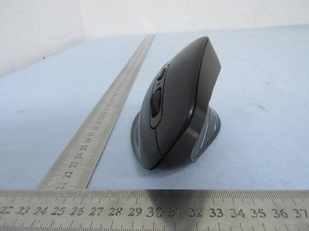
Click to zoom
Application Details
- Equipment Class
- DXX - Part 15 Low Power Communication Device Transmitter
- Date of Grant
- Oct 09, 2020
- Application Purpose
- Original Equipment
- Date of Application
- Oct 09, 2020
- Equipment Note
- Wireless Mouse
- Frequency Range
- 2403.00000000 - 2480.00000000
- Country
- China
Documents & Files
Document Text
Text extracted from the exhibit documents filed with the FCC. Open a document above to read the original.
Users Manual
PC324A User Manual VER: 0.1 Page 1 of 7 Model NAME : Wireless Mouse MODEL NO. : TM231 VERSION : 0.1 DATE : 2020.9.16 USER MANUAL PC324A User Manual VER: 0.1 Page 2 of 7 Version. # Revised Date PIC Remark 0.1 16/9/2020 Bob Preliminary PC324A User Manual VER: 0.1 Page 3 of 7 Electrical Specification 1. Operating Voltage Mouse supply voltage: 3.7V (Lithium-ion Battery) 2. Current Consumption Current use :< 20mA 3. Sleep Mode 3.1 Electrical Current: <1mA; 3.2 Wake Up: Press any button 5. Mouse Pointer Performance 5.1 Resolution: 800/1200(default)/1600/2000/2400 DPI 5.2 Speed: 30 inches/sec (Max) 5.3 Acceleration:10G 6. LED Indicating Functions When the battery power is low (battery voltage reduce to <3.4V) the LED will glisten at the frequency of 1Hz PC324A User Manual VER: 0.1 Page 4 of 7 7. Wireless specifications 2.403-2.480 GHz frequency coverage. GFSK RF transceiver High Speed RF link data rate Max. 1M bit/s Button Functions 1. Left Button: Mouse left button standard function 2. Right Button: Mouse right button standard function 3. Middle Button: Mouse middle button standard function 4. Wheel: Mouse scroll wheel standard function 5. 4 Button: IE Forward function 6. 5 Button: IE Back function 7. DPI Button: DPI regulate function 8. Mode switch Button:change to different chanel 9. Light switch Button: change the light mode PC324A User Manual VER: 0.1 Page 5 of 7 Operation Process Step 1 Open the battery cover which in the back of the Mouse. Step 2 Place the mouse on a desk or other plane surface. The surface material isn’t metal is better for wireless distance. Step 3 Insert a Transceiver in a USB port of PC. The Transceiver is pairing with the mouse. Step 4 Use the mouse freely. PC324A User Manual VER: 0.1 Page 6 of 7 Caution Please use the Mouse in human house only and keep away water. Don’t to fixate the light at the mouse bottom. Children use the mouse with guardian together is necessary. Keep dry. Humidity, liquids, contain minerals that will corrode electronic circuits. Don’t use or store in dusty, dirty areas. Don’t store in hot areas. High temperature can shorten the life of electronic devices and warp or melt certain plastics. Don’t store in very cold areas. Moisture can form inside the case, which may damage electronic circuit boards. Don’t attempt to open the case. Non-expert handling of the device may damage the system. Avoid dropping and strong impact. PC324A User Manual VER: 0.1 Page 7 of 7 FCC COMPLIANCE STATEMENT: This device complies with part 15 of the FCC Rules. Operation is subject to the following two conditions: (1) This device may not cause harmful interference, and (2) this device must accept any interference received, including interference that may cause undesired operation. Note: This equipment has been tested and found to comply with the limits for a Class B digital device, pursuant to Part 15 of the FCC Rules. These limits are designed to provide reasonable protection against harmful interference in a residential installation. This equipment generates, uses and can radiate radio frequency energy and, if not installed and used in accordance with the instructions, may cause harmful interference to radio communications. However, there is no guarantee that interference will not occur in a particular installation. If this equipment does cause harmful interference to radio or television reception, which can be determined by turning the equipment off and on, the user is encouraged to try to correct the interference by one or more of the following measures: Reorient or relocate the receiving antenna. Increase the separation between the equipment and receiver. Connect the equipment into an outlet on a circuit different from that to which the receiver is connected. Consult the dealer or an experienced radio/TV technician for help. Warning: Changes or modifications to this unit not expressly approved by the part responsible for compliance could void the user’s authority to operate the equipment. FCC Radiation Exposure Statement The device has been evaluated to meet general RF exposure requirement. The device can be used in portable exposure condition without restriction.
External Photos
FCC ID: 2AGLG-TM231 External photo FCC ID: 2AGLG-TM231 FCC ID: 2AGLG-TM231
ID Label/Location Info
TM231 2AGLG-TM231 Label Location
Internal Photos
FCC ID: 2AGLG-TM231 Internal photo FCC ID: 2AGLG-TM231 FCC ID: 2AGLG-TM231 FCC ID: 2AGLG-TM231 FCC ID: 2AGLG-TM231 RF Chip RF Antenna
Operational Description
DONGGUAN TOGRAN ELECTRONICS TECHNOLOGY CO.,LTD. Declaration concerning Antenna Specification It is hereby declared that the product Model No.: TM231 FCC ID: 2AGLG-TM231 fulfills the requirement in FCC test relating to the antenna type. The device specified above confirms to the FCC recommendations for Integral antenna type(s) described below: Model No. of antenna: 2.4G antenna Type of antenna: PCB antenna Gain of the antenna: -1.78 dBi Frequency range: 2403-2480MHz The mounting of the antenna is fixed to the radio module and no other antenna should be used. Company name: DONGGUAN TOGRAN ELECTRONICS TECHNOLOGY CO.,LTD. Address: 262 shidan Rd.,3rd industrial Area, Juzhou,Shijie Town, City: Dongguan city ZIP / Postal code: Country: China Place: China Date: 2020-10-09 Signature Sam Lin
RF Exposure Info
Dongguan Nore Testing Center Co., Ltd. Report No.: NTC2008295F-1 FCC ID: 2AGLG-TM231 RF EXPOSURE EVALUATION EUT Specification EUT Wireless Mouse Model Name TM231, PC324A, PC324B, PC324C Frequency band (Operating) 2.403GHz ~ 2.480GHz WLAN: 5.18GHz ~ 5.32GHz / 5.50GHz ~ 5.70GHz WLAN: 5.745GHz ~ 5825GHz Others(2402-2480MHz) Device category Portable (<20cm separation) Mobile (>20cm separation) Others ___ Antenna diversity Single antenna Multiple antennas Tx diversity Rx diversity Tx/Rx diversity Max. output power 94.42dBuV/m (-0.84dBm)(0.82mW) Antenna gain -1.78dBi Evaluation applied MPE Evaluation SAR Evaluation Standard Requirement Portable Device According to §15.247(i) and §1.1307b(1), systems operating under the provisions of this section shall be operated in a manner that ensures that the public is not exposed to radio frequency energy levels in excess of the Commission’s guidelines. See KDB 447498 D01 General RF Exposure Guidance v05, section 4.3.1. The 1-g and 10-g SAR test exclusion thresholds for 100 MHz to 6 GHz at test separation distances ≤ 50 mm are determined by: [(max. power of channel, including tune-up tolerance, mW)/(min. test separation distance, mm)] ·[√f(GHz)] ≤ 3.0 for 1-g SAR and ≤ 7.5 for 10-g extremity SAR, 16 where ·f(GHz) is the RF channel transmit frequency in GHz ·Power and distance are rounded to the nearest mW and mm before calculation17 ·The result is rounded to one decimal place for comparison The test exclusions are applicable only when the minimum test separation distance is ≤ 50 mm and for transmission frequencies between 100 MHz and 6 GHz. When the minimum test separation distance is < 5 mm, a distance of 5 mm is applied to determine SAR test exclusion. Dongguan Nore Testing Center Co., Ltd. Report No.: NTC2008295F-1 FCC ID: 2AGLG-TM231 Measurement Result Channel Frequency (MHz) Max Output power (dBuV/m) Max Output power (dBm) Max Output power (mW) Calculation Value (Note 1) Threshold Value 2403 94.41 -0.85 0.82 0.254 3.0 2441 93.72 -1.54 0.70 0.219 3.0 2480 94.42 -0.84 0.82 0.258 3.0 EIRP=E-104.8+20logD=94.42-104.8+20log3=-0.84dBm Note 1: Calculation Value =[(max. power of channel, mW)/(min. test separation distance, mm)] ·[√f(GHz)]. Fox example: 0.82/5*√2.480=0.258 ≤ 3.0 According to KDB447498 D01 V05, threshold at which no SAR required is ≤3.0 for 1-g SAR, separation distance is 5mm, and no SAR measurement is required. The SAR measurement is not necessary.
Test Report
Dongguan Nore Testing Center Co., Ltd. Report No.: NTC2008295FV00 FCC ID: 2AGLG-TM231 Page 2 of 27 Table of Contents 1. GENERAL INFORMATION ................................................................................................ 4 1.1 PRODUCT DESCRIPTION FOR EQUIPMENT UNDER TEST ................................................................. 4 1.2 RELATED SUBMITTAL(S) / GRANT (S) ............................................................................................ 6 1.3 TEST METHODOLOGY .................................................................................................................. 6 1.4 EQUIPMENT MODIFICATIONS ........................................................................................................ 6 1.5 SUPPORT DEVICE ....................................................................................................................... 6 1.6 TEST FACILITY AND LOCATION ..................................................................................................... 7 1.7 DEVIATIONS AND ABNORMALITIES FROM STANDARD CONDITIONS ................................................... 7 1.8 SUMMARY OF TEST RESULTS ....................................................................................................... 8 2. SYSTEM TEST CONFIGURATION .................................................................................... 9 2.1 EUT CONFIGURATION ................................................................................................................. 9 2.2 SPECIAL ACCESSORIES ............................................................................................................... 9 2.3 DESCRIPTION OF TEST MODES ..................................................................................................... 9 2.4 EUT EXERCISE ........................................................................................................................... 9 3. CONDUCTED EMISSIONS TEST .................................................................................... 10 3.1 TEST SET-UP (BLOCK DIAGRAM OF CONFIGURATION) ................................................................ 10 3.2 TEST CONDITION ....................................................................................................................... 10 3.3 MEASUREMENT RESULTS .......................................................................................................... 10 4. RADIATED EMISSION TEST ........................................................................................... 13 4.1 TEST SET-UP (BLOCK DIAGRAM OF CONFIGURATION) ................................................................ 13 4.2 MEASUREMENT PROCEDURE ..................................................................................................... 14 4.3 LIMIT ........................................................................................................................................ 15 4.4 MEASUREMENT RESULTS ................................................................................................. 16 5. 20DB BANDWIDTH .......................................................................................................... 20 5.1 MEASUREMENT PROCEDURE ..................................................................................................... 20 5.2 TEST SET-UP (BLOCK DIAGRAM OF CONFIGURATION) ................................................................ 20 5.3 MEASUREMENT RESULTS .......................................................................................................... 20 6. BAND EDGE .................................................................................................................... 23 6.1 MEASUREMENT PROCEDURE ..................................................................................................... 23 6.2 LIMIT ........................................................................................................................................ 23 6.3 MEASUREMENT RESULTS .......................................................................................................... 23 7. ANTENNA REQUIREMENT ............................................................................................. 26 7.1 MEASUREMENT PROCEDURE ..................................................................................................... 26 7.2 MEASUREMENT RESULTS .......................................................................................................... 26 8. TEST EQUIPMENT LIST .................................................................................................. 27 Dongguan Nore Testing Center Co., Ltd. Report No.: NTC2008295FV00 FCC ID: 2AGLG-TM231 Page 3 of 27 Revision History of This Test Report Report Number Description Issued Date NTC2008295FV00 Initial Issue 2020-09-29 Dongguan Nore Testing Center Co., Ltd. Report No.: NTC2008295FV00 FCC ID: 2AGLG-TM231 Page 4 of 27 1. GENERAL INFORMATION 1.1 Product Description for Equipment under Test Product Name : Wireless Mouse Main Model Number : TM231 Additional Model Number : PC324A, PC324B, PC324C Brand Name : N/A Power Supply : DC 5V from USB port DC 3.7V from internal battery Test Voltage : AC 120V 60Hz (Adapter Input), DC 3.7V from internal battery (Only the wors case was recorded in the report) Model Difference Description : These models have the same circuit schematic, construction, PCB Layout and critical components. Their difference in model number due to trading purpose. Hardware Version : V01 Software Version : V01 Serial number : 20I11 Note : N/A Remark : All the tests performed on model TM231. Technical Specification: 2.4G Function: Frequency Range : 2403~2480MHz Modulation Type : GFSK Number of Channel : 16 Antenna Type : PCB Antenna Gain : -1.78dBi (Declaration by manufacturer) Dongguan Nore Testing Center Co., Ltd. Report No.: NTC2008295FV00 FCC ID: 2AGLG-TM231 Page 5 of 27 Channel List: Channel Frequency…
Text truncated - open the document above for the full version.
Test Setup Photos
FCC ID: 2AGLG-TM231 Test photo Radiated emission Below 30M 30M-1G FCC ID: 2AGLG-TM231 Above 1G Conducted emission
Contact Information
Applicant
Bo Jiang
Test Firm
Dongguan NTC CO., Ltd.Jees Hong
[email protected]+86-769-22022444
Technical Specifications
| # | Rule Parts | Frequency Range | Power Output |
|---|---|---|---|
| 1 | 15C | 2.40 GHz - 2.48 GHz | 830.00 µW |
Other Applications from DONGGUAN TOGRAN ELECTRONICS TECHNOLOGY CO.,LTD.

2AGLG-TK404
Jan 01, 2025Scissor Keyboard receiver
Equipment Class
DTS - Digital Transmission System2AGLG-TK50FG-BK
Aug 28, 20242.4Ghz Split Ergo Keyboard with Trackball
Equipment Class
DSS - Part 15 Spread Spectrum Transmitter
2AGLG-LK150D
Oct 30, 2023Scissor Keyboard
Equipment Class
DTS - Digital Transmission System