2AGPO-AE-RD-BS05Motor Millimeter Wave Radar
AUTOEQUIPS TECH CO., LTD.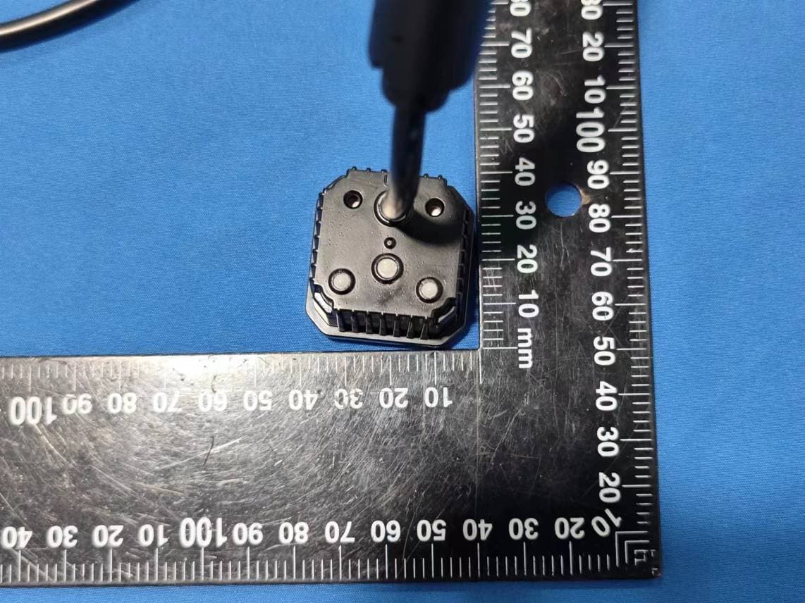
Click to zoom
Application Details
- Equipment Class
- VRD - Part 95 Vehicular Radar Systems
- Date of Grant
- Jun 26, 2023
- Application Purpose
- Original Equipment
- Date of Application
- Jun 26, 2023
- Equipment Note
- Motor Millimeter Wave Radar
- Frequency Range
- 77450.00000000 - 79450.00000000
- Company
- AUTOEQUIPS TECH CO., LTD.
- Country
- China
Documents & Files
Document Text
Text extracted from the exhibit documents filed with the FCC. Open a document above to read the original.
Users Manual
Product Manual system diagram System Components Radar M12-8 PIN black male with full thread M12-8 PIN black female head with full thread fuse 2A LED wire group 16CM Main line group M12-8 PIN black female head with full thread M12-8 black male with full thread Extension Extension 1M optional componentQty Radar host Main line group LED wire group 16CM Display Bracket accessory package 3.Technical Parameter Working voltage Rated voltage Working current Operation temperature Maximum detection distance Maximum detection width * LED display operating voltage range 10V-28V Product Name: Motor Millimeter Wave Radar Model:AE-RD-BS05 FCC ID: 2AGPO-AE-RD-BS05 Radar manual 4. Function Description 5. Alarm Mode Description Detection range 4.1 The radar module is connected to the vehicle ACC power supply and starts working after being powered on. 4.2 When the radar module detects an object, on the alarm: -Display the closest distance number; -Indicates that the object is located on the left or right side of the vehicle * For details, please refer to "5. Alarm Mode Description" The maximum detection range of the radar is 60M, and the width is 8M. Based on distance, the warning method is as follows Left LED Right LED Object on the left side of the vehicle Object on the right side of the vehicle Distance display, displayed when there is no detection - - conditions position display7-segment LED light Left LED Right LED Left Left Left Yes Yes Yes Yes Yes Yes Yes Right Right Right Middle Middle Middle TTC< 5 seconds TTC> 5 seconds Blind spot range Flicker Flicker Flicker Lighting Lighting Lighting Lighting Lighting Lighting Lighting Lighting Lighting Lighting Not lit Not lit Not lit Not lit Not lit Not lit Not lit Not lit Not lit Not lit Not lit Not lit Not lit Not lit Not lit Not lit Not lit Out-of-scope FCC Warning This device complies with part 15 of the FCC Rules. Operation is subject to the following two conditions: (1) This device may not cause harmful interference, and (2) this device must accept any interference received, including interference that may cause undesired operation. Any changes or modifications not expressly approved by the party responsible for compliance could void the user's authority to operate the equipment. This equipment has been tested and found to comply with the limits for a Class B digital device, pursuant to part 15 of the FCC Rules. These limits are designed to provide reasonable protection against harmful interference in a residential installation. This equipment generates, uses and can radiate radio frequency energy and, if not installed and used in accordance with the instructions, may cause harmful interference to radio communications. However, there is no guarantee that interference will not occur in a particular installation. If this equipment does cause harmful interference to radio or television reception, which can be determined by turning the equipment off and on, the user is encouraged to try to correct the interference by one or more of the following measures: —Reorient or relocate the receiving antenna. —Increase the separation between the equipment and receiver. —Connect the equipment into an outlet on a circuit different from that to which the receiver is connected. —Consult the dealer or an experienced radio/TV technician for help. FCC Radiation Exposure Statement This equipment complies with FCC radiation exposure limits set forth for an uncontrolled environment . This transmitter must not be co ‐located or operating in conjunction with any other antenna or transmitter. This equipment should be installed and operated with minimum distance 40cm between the radiator& your body.
Cover Letter(s)
QA-FR- 171-A AUTOEQUIPS TECH CO., LTD. Add: Rm 04/11F, Block C, Wanhai Building, No. 1030 Nanhai Avenue, Nanshan District, Shenzhen City, Guangdong Province, China Tel: +86-755-33663308 Fax: +86-755-33663309 Email: [email protected] FCC Confidential Authorization Date: 2023-06-06 FEDERAL COMMUNICATIONS COMMISSION Authorization and Evaluation Division 7435 Oakland Mills Road Columbia, MD 21046 Subject: Confidentiality Request regarding application for certification of FCC ID: 2AGPO-AE-RD-BS05 In accordance with Sections 0.457 and 0.459 of the Commission’s Rules, (AUTOEQUIPS TECH CO., LTD. ) hereby requests long-term confidential treatment of information accompanying this application as outlined below: Block Diagram Schematics/Tune up/BOM Operation Description The above materials contain proprietary and confidential information not customarily released to the public. The public disclosure of these materials provides unjustified benefits to its competitors in the market. Sincerely, Signature: Printed Name: Cathy Wang Title: General Manager
External Photos
EXHIBIT B - EUT EXTERNAL PHOTOGRAPHS EUT Port
ID Label/Location Info
32.00 mm 22.00 mm MODEL: AE-RD BS05 POWER: 12/24V DC - 10R-06 4231 Blind Spot Monitoring System FCC ID 2AGPO-AE-RD-BS05: label location 130mm 78mm 180mm 130 78 180
Internal Photos
EXHIBIT C - EUT INTERNAL PHOTOGRAPHS Uncover Chip Chip Chip Chip+Antenna TXAntenna RXAntenna
RF Exposure Info
China Certification ICT Co., Ltd (Dongguan) Report No.: CR230311651-00B Page 51 of 52 5. RF EXPOSURE EVALUATION 5.1 MAXIMUM PERMISSIBLE EXPOSURE (MPE) 5.1.1 Applicable Standard FCC §95.3385 & §1.1310 & §2.1091 Regardless of the power density levels permitted under this subpart, devices operating under the provisions of this subpart are subject to the radiofrequency radiation exposure requirements specified in §§ 1.1307(b), 2.1091, and 2.1093 of this chapter, as appropriate. Applications for equipment authorization of devices operating under this section must contain a statement confirming compliance with these requirements for both fundamental emissions and unwanted emissions. Technical information showing the basis for this statement must be submitted to the Commission upon request. Systems operating under the provisions of this section shall be operated in a manner that ensures that the public is not exposed to radio frequency energy levels in excess of the Commission's guidelines. See §1.1307(b)(1) of this chapter. Limits for Maximum Permissible Exposure (MPE) (§1.1310, §2.1091) (B) Limits for General Population/Uncontrolled Exposure Frequency Range (MHz) Electric Field Strength (V/m) Magnetic Field Strength (A/m) Power Density (mW/cm 2 ) Averaging Time (minutes) 0.3–1.34 614 1.63 *(100) 30 1.34–30 824/f 2.19/f *(180/f²) 30 30–300 27.5 0.073 0.2 30 300–1500 / / f/1500 30 1500–100,000 / / 1.0 30 f = frequency in MHz; * = Plane-wave equivalent power density; According to §1.1310 and §2.1091 RF exposure is calculated. 5.1.2 Procedure Prediction of power density at the distance of the applicable MPE limit S = PG/4R² = power density (in appropriate units, e.g. mW/cm 2 ); P = power input to the antenna (in appropriate units, e.g., mW); G = power gain of the antenna in the direction of interest relative to an isotropic radiator, the power gain factor, is normally numeric gain; R = distance to the center of radiation of the antenna (appropriate units, e.g., cm); China Certification ICT Co., Ltd (Dongguan) Report No.: CR230311651-00B Page 52 of 52 5.2 Measurement Result Frequency (GHz) Antenna Gain Conducted output power including Tune-up Tolerance Evaluation Distance (cm) Power Density (mW/cm 2 ) MPE Limit (mW/cm 2 ) (dBi) (numeric) (dBm)(mW) 77.45-79.45 3.00 2 4010000 400.9947 1 Result: The device meet FCC MPE at 40 cm distance. ===== END OF REPORT =====
Test Report
AntennaDatasheet Manufacturer:CalterahType :Patch Antenna Specification: ItemFrequencyAntenna Gain (Center Frequency) CAL77S244-AB77-81GHz3dBi 1. Configuration: Figure 1 Configurationof CAL77S244-AB 2. TXAntennaSimulationResults Figure 2S11 for TX Antennas Figure3IsolationbetweenTXAntennas Figure4RadiationPatternforTXAntennasat77GHz 3.RXAntennaSimulationResults Figure5S11forRXAntennas Figure6IsolationbetweenRXAntennas Figure7RadiationPatternforRXAntennasat77GHz
Test Report
TEST REPORT Applicant: AUTOEQUIPS TECH CO., LTD. Address: Rm 04/11F, Block C, Wanhai Building, No. 1030 Nanhai Avenue, Nanshan District, Shenzhen City, Guangdong Province, China FCC ID: 2AGPO-AE-RD-BS05 Product Name: Motor Millimeter Wave Radar Standard(s): 47 CFR Part 95, Subpart M ANSI C63.26-2015 KDB 653005 D01 76-81 GHz Radars v01r02 The above equipment has been tested and found compliant with the requirement of the relative standards by China Certification ICT Co., Ltd (Dongguan) Report Number: CR230311651-00B Date Of Issue: 2023/6/26 Reviewed By: Sun Zhong Title: Manager Test Laboratory: China Certification ICT Co., Ltd (Dongguan) No. 113, Pingkang Road, Dalang Town, Dongguan, Guangdong, China Tel: +86-769-82016888 China Certification ICT Co., Ltd (Dongguan) Report No.: CR230311651-00B Page 2 of 52 Test Facility The Test site used by China Certification ICT Co., Ltd (Dongguan) to collect test data is located on the No. 113, Pingkang Road, Dalang Town, Dongguan, Guangdong, China. The lab has been recognized as the FCC accredited lab under the KDB 974614 D01 and is listed in the FCC Public Access Link (PAL) database, FCC Registration No. : 442868, the FCC Designation No. : CN1314. The lab has been recognized by Innovation, Science and Economic Development Canada to test to Canadian radio equipment requirements, the CAB identifier: CN0123. Declarations China Certification ICT Co., Ltd (Dongguan) is not responsible for the authenticity of any test data provided by the applicant. Data included from the applicant that may affect test results are marked with a triangle symbol “▲”. Customer model name, addresses, names, trademarks etc. are not considered data. Unless otherwise stated the results shown in this test report refer only to the sample(s) tested. This report cannot be reproduced except in full, without prior written approval of the Company. This report is valid only with a valid digital signature. The digital signature may be available only under the Adobe software above version 7.0. This report may contain data that are not covered by the accreditation scope and shall be marked with an asterisk “★”. China Certification ICT Co., Ltd (Dongguan) Report No.: CR230311651-00B Page 3 of 52 CONTENTS T EST FACILITY .......................................................................................................................................... 2 DECLARATIONS .......................................................................................................................................... 2 DOCUMENT REVISION HISTORY .......................................................................................... 5 1. GENERAL INFORMATION .................................................................................................... 6 1.1 PRODUCT DESCRIPTION FOR EQUIPMENT UNDER TEST (EUT) ....................................................... 6 1.2 DESCRIPTION OF TEST CONFIGURATION ........................................................................................... 7 1.2.2 Support Equipment List and Details .............................................................................................................. 7 1.2.3 Support Cable List and Details ...................................................................................................................... 7 1.2.4 Block Diagram of Test Setup ......................................................................................................................... 8 1.3 MEASUREMENT UNCERTAINTY .......................................................................................................... 9 2. SUMMARY OF TEST RESULTS .......................................................................................... 10 3. REQUIREMENTS AND TEST PROCEDURES .................................................................. 11 3.1 RADIATED POWER ............................................................................................................................. 11 3.1.1 Applicable Standard ..................................................................................................................................... 11 3.2.2 EUT Setup.................................................................................................................................................... 11 3.2.3 Test Procedure ............................................................................................................................................. 12 3.2 UNWANTED EMISSIONS ..................................................................................................................... 13 3.2.1 Applicable Standard ..................................................................................................................................... 13 3.2.2 EUT Setup.................................................................................................................................................... 14 3.2.3 EMI Test Receiver & Spectrum Analyzer Setup ......................................................................................... 16 3.2.4 Test Procedure ............................................................................................................................................. 16 3.2.5 Corrected Amplitude & Margin Calculation ................................................................................................ 17 3.3 FREQUENCY STABILITY: ................................................................................................................... 18 3.3.1 Applicable Standard ..................................................................................................................................... 18 3.3.3 Test Procedure ............................................................................................................................................. 18 3.4 OCCUPIED BANDWIDTH: .......................................................…
Text truncated - open the document above for the full version.
Test Setup Photos
EXHIBIT D - TEST SETUP PHOTOGRAPHS Radiated Emission 30M-1GHz View Radiated Emission 9k-30MHz View Parallel Radiated Emission 9k-30MHz View Perpendicular Radiated Emission 9k-30MHz View Ground-parallel Radiated Emission Above 1GHz View Radiated Emission Above 1GHz View 18G-26.5G Radiated Emission Above 1GHz View 26.5G-40G Radiated Emission Above 1GHz View 40G-60G Radiated Emission Above 1GHz View 60G-90G Radiated Emission Above 1GHz View 90G-140G Radiated Emission Above 1GHz View 140G-220G Radiated Emission Above 1GHz View220G-231G
Contact Information
Applicant
Cathy Wang(General Manager)
Test Firm
CHINA CERTIFICATION ICT CO., LTD (DONGGUAN)Tanie Ou
[email protected]0086 0769 86858888
Technical Specifications
| # | Rule Parts | Frequency Range | Power Output | Emission |
|---|---|---|---|---|
| 1 | 95M | 77.45 GHz - 79.45 GHz | 17.46 W | 2G00F0N |