2AGRQR1Charm Ring
ZTE STRAWCOM Communication Co., Ltd.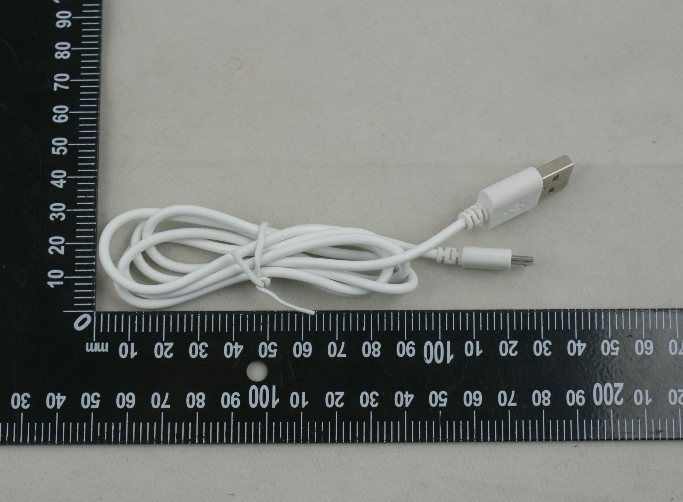
Click to zoom
Application Details
- Equipment Class
- DTS - Digital Transmission System
- Date of Grant
- Dec 14, 2015
- Application Purpose
- Original Equipment
- Date of Application
- Dec 14, 2015
- Equipment Note
- Charm Ring
- Frequency Range
- 2402.00000000 - 2480.00000000
- Country
- China
Documents & Files
Document Text
Text extracted from the exhibit documents filed with the FCC. Open a document above to read the original.
Users Manual
第1页 第2页 R1 FCCID:2AGRQR1 OperationManual 1. Product introduction Icharming, a combination of technology and fashion and a crossover of tradition and internet, CharmRing has powerful and practical functions with stylish appearance. 1、 Capable of setting photo-taking function by gesture at yours own will. Industry’s longest Bluetooth-controlled photo-taking distance, up to 10 meters. 2、 Health function could give you professional advice about sport data that display by APP. CharmRing could be used for step counter without mobile phone. 3、 The ring will flash on call. You may stop worry about missing any important calls if your cell phone is not handy. 4、 In case of oblivion or anti-loss, CharmRing link with mobile phone by bluetooth,it could alert their owners to know that the ring or the mobile phone is far away. 5、 In emergency situations, your friends and relatives(preinstall the emergency contact phone number by APP) will receive warning message and positional information by special gesture. Warning message contains preinstall text and instant positional information. 6、 You could share motion data,photos among social circle. Sharing a joy is 第3页 a happiness. 7、 Do not use the Charm Ring in the environment at too high or too low Temperature, never expose the device under strong sunshine or too wet environment. The suitable temperature for the phone and accessories is 0-45 °C 2. Product list Charm Ring R1 product list : 1、 Charm Ring R1 2、 Portable charging case 3、 USB power line 4、 Diamond flat cloth 5、 Operation instruction 6、 Certificate of warranty card 3. diagram of product appearance 第4页 4. Product Features Guide First use of this product, please read the manual, operate according to the instructions: 1. Open the product box and check products according to the checklist. 2. 第5页 There is a switch(ON/OFF) on the bottom of charging case. Turn on the switch, the ring is opening in the charging case. The ring could be linked with Bluetooth. Turn off the switch, the ring is closed and all functions are closed. At ordinary times, put the switch in on. Only under the long-term unused situation, please turn off the switch(off) 3. Please take out of USB that placed in packaging box of lining small cardboard box. The Fist-time user needs to charge Ring and case before using. This product does not provide power adapter and other mobile phone’s power adapter could be used,The USB is Charging only. 4. Tear up the protective film and to make sure that charging sports could be contacted with charging case. 5. While it is charging, put ring in the charging case(please aware of the direction of ring). Please turn charging contacts inward or it would not be recharged. While it is charging, cover with the lid, state indicator lamp is on means the ring is charging. When the charging capacity is full, state indicator lamp will go out. The recharge time is about one hour. Please note that the ring could be charged only when the lid is closed. 6. The charging case has set-in battery, when the charging case has power it could charge the ring without any external power source. When the charging case out of power, the case needs the external power source. The charging case could be used on a single full charge. 第6页 The state indicator lamp 2 is on, it means the ring is charging(external power source is be linked). When the top state indicator lamp 1 is on, it means the charging case is recharged. When remove the USB cable for charging, state indicator lamp 2 will be off. The recharge time of case is about 1.5hours. 7. Before using, you need to install APP. The ring need to used with APP and the related function could be achieved. (1) Before using, you need to install APP which supports Android 4.3 version and above. IPHONE needs IOS 7.0 and above. If mobile phone does not satisfy requirements, the APP will not be installed. (2) Before using, mobile phone needs to install APP. Scanning QR code to get the APP. Clicking the web links to get the APP. 第7页 http://www.strawcom.com/android.html http://www.strawcom.com/ios.html 5. APP instructions 1. User Registration and Bluetooth Link (1) The first-time user needs to fill out the customer register correctly, so that we can offer you with better service and exercise suggestion. We will not divulge the information or use it for any other 第8页 purpose. 第9页 (2) After finishing the registration, entering APP interface to bind the ring. Clicking top-left icon for entering the setting screen and menu list. Selecting the first option “Charm Ring not connected” and choosing the need option in the search listing to link the Bluetooth. 第10页 第11页 第12页 第13页 When a ring linked with mobile phone, the user menu “Charm Ring unconnected”will show the ring battery which means you could use the ring as a result of the successful bind. (3) If the searching or binding is failure, please to make sure Bluetooth is turn on. The ring and mobile phone should in the coverage of communication. Please keep the ring as close as possible to the mobile phone for successfully connection. 第14页 2. personal information setting 第15页 3. optional switch setting 第16页 When using, please open all the function switch for using. The light notification could be changed by the slider of “call notification” and “phone lost notification”. 4. motion calculation (1)set the fitness goals, you could set the fitness goals based on individual requirement. 第17页 (2) APP will record your motion data for good fitness habit everyday. 第18页 (3) Ranking 第19页 5. Emergency setting 第20页 Contacts in the emergency list will receive warning message and current positional with the ring wiggled frequently. 第21页 Warning message contains positional information and warning information. 6. Notice and disclaimer 1. The Continuous time of battery endurance is about 20hours. Fully charged case could use 7~10days. The battery time of ring is according to the actual usage. 2. The Continuous time of ba…
Text truncated - open the document above for the full version.
External Photos
AnnexNo.:BL-SZ1590140-AW EUTEXTERNALPHOTOS THEFRONTOFEUT THEBACKOFEUT AnnexNo.:BL-SZ1590140-AW 2 / 5 THELEFTOFEUT THERIGHTOFEUT AnnexNo.:BL-SZ1590140-AW 3 / 5 THEUPOFEUT THEDOWNOFEUT AnnexNo.:BL-SZ1590140-AW 4 / 5 CHARGER THEUSBPORTOFCHARGERPHOTO AnnexNo.:BL-SZ1590140-AW 5 / 5 THEUSBPHOTO
ID Label/Location Info
FCC ID:2AGRQR1 CE0700 location
Internal Photos
Annex No.:BL-SZ1590140-AI EUTINTERNALPHOTOS E UTPhoto1 EUTPhoto2 Annex No.:BL-SZ1590140-AI 2 / 9 E UTPhoto3 E UTPhoto4 Annex No.:BL-SZ1590140-AI 3 / 9 E UTPhoto5 E UTPhoto6 Annex No.:BL-SZ1590140-AI 4 / 9 EUTPhoto7 EUTPhoto8 Annex No.:BL-SZ1590140-AI 5 / 9 E UTPhoto9 E UTPhoto10 Annex No.:BL-SZ1590140-AI 6 / 9 E UTPhoto11 E UTPhoto12 Annex No.:BL-SZ1590140-AI 7 / 9 E UTPhoto13 E UTPhoto14 Annex No.:BL-SZ1590140-AI 8 / 9 E UTPhoto15 E UTPhoto16 Annex No.:BL-SZ1590140-AI 9 / 9 E UTPhoto17 E UTPhoto18
RF Exposure Info
RF Exposure Evaluation for FCC ID: 2AGRQR1 Refer user manual this device is a Charm Ring and this device was designed used in portable devices the minimum distance between human’s body is 5mm. Based on the 47CFR 2.1093, this device belongs to portable device. The definition of the category as following: Po r table Derives: CFR Title 47 §2.1093(b) (b) For purposes of this section, a portable device is defined as a transmitting device designed to be used so that the radiating structure(s) of the device is/are within 20 centimeters of the body of the user. FCC KDB 447498 D01 General RF Exposure Guidance v0 5r02 Limit Unless specifically required by the published RF exposure KDB procedures, standalone 1‐g head or body and 10‐g extremity SAR evaluation for general population exposure conditions, by measurement or numerical simulation, is not required when the corresponding SAR Test Exclusion Threshold condition, listed below, is satisfied. These te st e xclusion conditions are based on source‐based time‐averaged maximum conducted output power of the RF channel requiring evaluation, adjusted for tune‐up tolerance, and the minimum test separation distance required for the exposure conditions. The minimum test separation distance is determined by the smallest distance from the antenna and ra d iating structures or outer surface of the device, according to the host form factor, exposure conditions and platform requirements, to any part of the body or extremity of a user or bystander. The 1‐g and 10‐g SAR test exclusion thresholds for 100 MHz to 6 GHz at te st separ ation distances ≤ 50 mm are determined by: [ ሺ୫ୟ୶.୮୭୵ୣ୰ ୭ ୡ୦ୟ୬୬ୣ୪,୧୬ୡ୪୳ୢ୧୬ ୲୳୬ୣି୳୮ ୲୭୪ୣ୰ୟ୬ୡୣ,୫ሻ ሺ୫୧୬.୲ୣୱ୲ ୱୣ୮ୟ୰ୟ୲୧୭୬ ୢ୧ୱ୲ୟ୬ୡୣ,୫୫ሻ ] ∙ [ ඥ f ሺୋୌሻ ] ≤ 3.0 for 1‐g SAR and ≤ 7.5 for 10‐g extremity SAR Where • f (GHz) is the RF channel transmit frequency in GHz • Power and distance are rounded to the nearest mW and mm before calculation • The result is rounded to one decimal place for comparison The test e xclusions are applicable only when the minimum test separation distance is ≤ 50 mm and for transmission frequencies between 100 MHz and 6 GHz. When the minimum test separation distance is < 5 mm, a distance of 5 mm is applied to determine SAR test exclusion. FCC exclusion condition= [ ሺ.଼,୫ሻ ሺହ,୫୫ሻ ] ∙ [ ඥ 2.402 ሺୋୌሻ ] = 0.212 < 3.0 RF Exposure Evaluation Result: Pass Note: More power data, Please refer to the RF report.
Test Report
Report No.: BL-SZ1590140-601 2 Revision History Version Issue Date Revisions Rev. 01 Dec. 4, 2015 Initial Issue TABLE OF CONTENTS 1 ADMINISTRATIVE DATA (GENERAL INFORMATION) .......................................................................... 5 1.1 Identification of the Testing Laboratory .............................................................................................. 5 1.2 Identification of the Responsible Testing Location ............................................................................. 5 1.3 aboratory Condition ............................................................................................................................ 5 1.4 Announce ........................................................................................................................................... 5 2 PRODUCT INFORMATION ...................................................................................................................... 7 2.1 Applicant ............................................................................................................................................ 7 2.2 Manufacturer ...................................................................................................................................... 7 2.3 Factory Information ............................................................................................................................ 7 2.4 General Description for Equipment under Test (EUT) ....................................................................... 7 2.5 Ancillary Equipment ........................................................................................................................... 7 2.6 Technical Information ......................................................................................................................... 8 3 SUMMARY OF TEST RESULTS .............................................................................................................. 9 3.1 Test Standards ................................................................................................................................... 9 3.2 Verdict ................................................................................................................................................ 9 4 GENERAL TEST CONFIGURATIONS ................................................................................................... 10 4.1 Test Environments ........................................................................................................................... 10 4.2 Test Equipment List ......................................................................................................................... 10 4.3 Test Configurations .......................................................................................................................... 11 4.4 Description of Test Setup ................................................................................................................. 11 4.4.1 For Antenna Port Test ............................................................................................................... 11 4.4.2 For AC Power Supply Port Test ................................................................................................ 11 4.4.3 For Radiated Test (Below 30 MHz) ........................................................................................... 12 4.4.4 For Radiated Test (30 MHz-1 GHz) .......................................................................................... 12 4.4.5 For Radiated Test (Above 1 GHz) ............................................................................................. 13 Report No.: BL-SZ1590140-601 3 4.5 Test Conditions ................................................................................................................................ 13 5 TEST ITEMS ........................................................................................................................................... 14 5.1 Antenna Requirements .................................................................................................................... 14 5.1.1 Standard Applicable .................................................................................................................. 14 5.1.2 Antenna Anti-Replacement Construction .................................................................................. 14 5.1.3 Antenna Gain ............................................................................................................................ 14 5.2 Output Power ................................................................................................................................... 15 5.2.1 Test Limit ................................................................................................................................... 15 5.2.2 Test Setup ................................................................................................................................. 15 5.2.3 Test Procedure .......................................................................................................................... 15 5.2.4 Test Result ................................................................................................................................ 16 5.3 6 dB Bandwidth ................................................................................................................................ 17 5.3.1 Limit ........................................................................................................................................... 17 5.3.2 Test Setup ................................................................................................................................. 17 5.3.3 Test Procedure .......................................................................................................................... 17 5.3.4 Test Re…
Text truncated - open the document above for the full version.
Test Setup Photos
Annex No.:BL-SZ1590140-AR TEST SETUP PHOTOS 1Radiated Test Photo Below 30MHz 30 MHz-1 GHz Annex No.:BL-SZ1590140-AR Above 1GHz Above 1GHz Annex No.:BL-SZ1590140-AR 2Conducted Test Photo Conducted Test 3Conducted Emission Conducted Emission Test
Contact Information
Applicant
yanhua gong(manager)
Test Firm
Shenzhen BALUN Technology Co.,Ltd.Xuewen Wu
Technical Specifications
| # | Rule Parts | Frequency Range | Power Output |
|---|---|---|---|
| 1 | 15C | 2.40 GHz - 2.48 GHz | 680.00 µW |