2AGZ4-ATCONNECTAn AutoInjector with Bluetooth low energy feature
Amgen Inc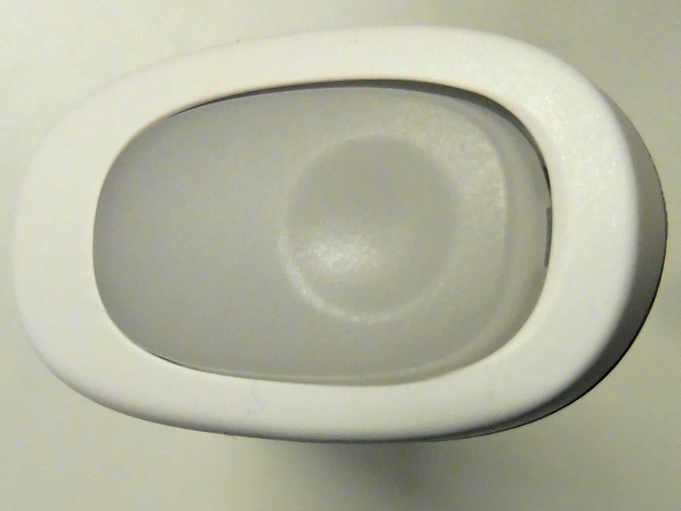
Click to zoom
Application Details
- Equipment Class
- DTS - Digital Transmission System
- Date of Grant
- May 09, 2021
- Application Purpose
- Original Equipment
- Date of Application
- May 09, 2021
- Equipment Note
- An AutoInjector with Bluetooth low energy feature
- Frequency Range
- 2402.00000000 - 2480.00000000
- Company
- Amgen Inc
- Country
- United States
Documents & Files
Document Text
Text extracted from the exhibit documents filed with the FCC. Open a document above to read the original.
Users Manual
ILL2316 v1 ILL0963 v1 AutoTouch Connect TM reusable autoinjector for use with Enbrel Mini ® (etanercept) single-dose prefilled cartridge User Manual 3 Table of Contents Getting Started .............................................4 Reference Guide ...........................................5 Resources ....................................................6 Guide to Parts ...............................................8 Troubleshooting: Error Symbols ...................18 Troubleshooting: Common Problems ...........24 Storage & Handling .....................................28 Cleaning Instructions ..................................30 Warnings ....................................................31 What is the Bluetooth ® wireless feature? ....32 Technical Information ..................................36 Symbol Table ..............................................41 4 This User Manual contains helpful information about your AutoTouch Connect TM reusable autoinjector (AutoTouch Connect). It includes resources, care details, and a troubleshooting guide to save for ongoing reference. To learn how to inject using AutoTouch Connect, see your healthcare provider for injection training and use the Instructions for Use included in the carton. Instructions for Use A fold-out, step-by-step Instructions for Use is provided in the carton, which provides you with full instructions to learn how to give yourself a safe, successful and accurate injection. Note: Please read the full Instructions for Use included in the carton. The Reference Guide on the next page should only be used when you have successfully completed an injection using the Instructions for Use. Getting Started 5 Reference Guide ILL0985 v2 1 4 5 3 Prepare and clean your injection site. Hold the Enbrel Mini ® single-dose prefilled cartridge with labeled side facing out and slide into door. Close door. Remove purple cap. Place and hold on skin. Wait for the status button to turn green. To start injection: Press and release the green status button. Injection is finished when you hear a chime and all lights are turned off. ILL0125 v4 Upper armStomach area (abdomen) Status button flashes Thigh ILL0984 v2 ILL0978 v2 ILL0980 v1 ILL0960 v1 ILL0965 v7 Labeled side ILL0959 v4 ILL0974 v5 2 6 Resources ENBREL Support ® provides personalized support services to ENBREL ® patients, at no additional cost, including: • Information about financial support options • Supplemental injection training with an ENBREL Nurse Partner ™ • Educational materials to help support you along the way Call 1-888-4ENBREL (1-888-436-2735) to enroll or visit www.EnbrelSupport.com to find out more. 7 8 ILL0968 v3 Guide to Parts AutoTouch Connect TM reusable autoinjector Viewing window Finger grip Door Door button 9 ILL0972 v2 Finger grip When injecting, hold the AutoTouch Connect TM reusable autoinjector with fingers wrapped around the gray finger grip. Door button Press this button to open the door for insertion of the Enbrel Mini ® single-dose prefilled cartridge. When your injection is finished, the door will open automatically. Viewing window During an injection, you can look through this window and see the plunger lowering to deliver your medicine. When AutoTouch Connect is awake, the viewing window will light up. If Enbrel Mini is in AutoTouch Connect, and the viewing window has no light, then press the status button to wake up AutoTouch Connect. You will open this door and insert Enbrel Mini into AutoTouch Connect. The door will open automatically when your injection is finished. When inserted properly, Enbrel Mini will slide freely and completely into and out of the door. 10 ILL0969 v3 Guide to Parts AutoTouch Connect TM reusable autoinjector Progress bar Error symbols Speaker Status button Speed switch 11 Status button Press this button to begin an injection. Lights will indicate the status of your injection. Green: Ready to press and start injection. Blinking green: The needle is inserting and your injection is in progress. Red: An error has occurred. See the Troubleshooting section of this manual. Progress bar These stacked green bars are fully lit when your injection starts, and the bar of lights decrease as your injection is in progress. The lights will disappear when your injection is finished. Speed switch The AutoTouch Connect TM reusable autoinjector allows you to choose from three injection speeds. The pre-set speed is medium. (+) is faster (•) is medium (–) is slower 12 ILL0970 v2 Guide to Parts AutoTouch Connect TM reusable autoinjector Sound switch Injection end 13 Sound switch Sounds can be turned off and on. (Sounds on) Slide switch down. (Sounds off) Slide switch up so that the red bar is visible. Note: Error sounds will still be heard if the sounds have been turned off. Injection end The entire injection end must be touching your skin during injections. This is also where the needle will come out. Skin sensor A skin sensor is located on the injection end. When the injection end is placed on skin the start button light will turn green. Hold the injection end flat and steady on your skin throughout the entire injection process. Site light When the Enbrel Mini ® single-dose prefilled cartridge is loaded and the purple cap is removed, the injection end will light up to help you see your injection site. 14 ILL2314 v1 ILL2315 v1 Enbrel Mini ® single-dose prefilled cartridge Purple cap on Medicine Expiration date Labeled side Enbrel Mini window (with medicine) Enbrel Mini window (without medicine) Important: The needle is inside Enbrel Mini Purple cap off Before use After use Guide to Parts 15 Labeled side When inserting the Enbrel Mini ® cartridge make certain that the labeled side is facing out. Then slide Enbrel Mini into the door. It will slide all the way down into the AutoTouch Connect TM reusable autoinjector. Expiration date Confirm expiration date printed on the label has not passed. Enbrel Mini window This is where you will look to examine your medicine …
Text truncated - open the document above for the full version.
Cover Letter(s)
FCC Agent Authorization Letter Federal Communications Commission Authorization and Evaluation Division 1435 Oakland Mills Road Columbia, MD 21046 Date: __________________ SUBJECT: FCC Application for FCC ID: _______________________________ To Whom It May Concern: We, the undersigned, hereby authorize _________________________________________ in _____________________________________________ on our behalf, to apply to the Federal Communications Commission for our equipment. Any and all acts carried out by _____________________________________________ on our behalf shall have the same effect as acts of our own. This is to advise that we are in full compliance with the Anti- Drug Abuse Act. We, the applicant, are not subject to a denial of federal benefits pursuant to Section 5301 of the Anti-Drug Act of 1988, 21 USC853a, and no party to the application is subject to a denial of federal benefits pursuant to that section. Sincerely, Client’s signature: ________________________________ Client’s name & title: _____________________________ Contact information / address: DocuSign Envelope ID: 4E5C12EB-0DD1-46F4-A1D9-7C34948E6E43 [email protected] 4/14/2021
Cover Letter(s)
Federal Communications Commission Authorization and Evaluation Division Confidentiality Request regarding application for certification of FCC ID: ________________ Pursuant to Sections 0.457 and 0.459 of the Commission’s Rules, we hereby request confidential treatment of information accompanying this application as outlined below: Type of Confidentiality Requested Exhibit Type ☐Short Term ☐Permanent Block Diagrams ☐Short Term External Photos ☐Short Term ☐Permanent* Internal Photos ☐Short Term ☐Permanent Operation Description ☐Short Term ☐Permanent Parts List/BOM ☐Short Term ☐Permanent Schematics ☐Short Term Test Setup Photos ☐Short Term ☐Permanent* User manual *Requires further justification before permanent confidentiality will be allowed. The above materials contain trade secrets and proprietary information not customarily released to the public. The public disclosure of these materials may be harmful to the applicant and provide unjustified benefits to its competitors. Permanent Confidentiality: The applicant requests the exhibits listed above as permanently confidential be withheld from public review due to materials that contain trade secrets and proprietary information not customarily released to the public. Short-Term Confidentiality: Pursuant to DA04-1705 June 15, 2004 of the Commission’s public notice, we also request temporary confidential treatment of information accompanying this application as outlined below for an initial period of ____________ days. Sincerely, Client’s signature: ________________________________ Client’s name & title: _____________________________ Contact information / address: DocuSign Envelope ID: E0FA7669-4687-45BD-97EE-FFF6D0327DEA [email protected] 4/13/2021
External Photos
Annex A 1-8743/19-02-01_AnnexA External photos of the Equipment Under Test This addendum is electronically signed and valid without handwritten signature. For verification of the electronic signatures, the public keys can be requested at the testing laboratory. Document authorized: Mihail Dorongovskij Lab Manager Radio Communications & EMC CTC advanced GmbHUntertuerkheimer Str. 6-10 66117 Saarbruecken / Germany Phone: +49 681 5 98 - 0 Fax: +49 681 5 98 - 9075 web: ctcadvanced.com e-mail: [email protected] Photos Photo 1: EUT front side view Photo 2: EUT back side view 2019-08-23Document No. 1-8743/19-02-01_AnnexA2/6 Photo 3: EUT right side view Photo 4: EUT left side view 2019-08-23Document No. 1-8743/19-02-01_AnnexA3/6 Photo 5: EUT bottom side view Photo 6: EUT top side view 2019-08-23Document No. 1-8743/19-02-01_AnnexA4/6 Photo 7: EUT bottom side view 2019-08-23Document No. 1-8743/19-02-01_AnnexA5/6 Document history VersionApplied changesDate of release initial release2019-08-23 - END OF DOCUMENT - 2019-08-23Document No. 1-8743/19-02-01_AnnexA6/6
Internal Photos
AutoTouch Connect TM Internal photo 1 AutoTouch Connect TM Internal phone 2 Amgen Proprietary and Confidential AutoTouch Connect TM Internal phone 3 AutoTouch Connect TM Internal phone 4 AutoTouch Connect TM Internal phone 5 Amgen Proprietary and Confidential AutoTouch Connect TM Internal phone 6 AutoTouch Connect TM Internal phone 7 Amgen Proprietary and Confidential AutoTouch Connect TM PCB#1‐Top view AutoTouch Connect TM PCB#1‐Bottom view Amgen Proprietary and Confidential AutoTouch Connect TM PCB#2‐Top view AutoTouch Connect TM PCB#2‐Bottom view Amgen Proprietary and Confidential AutoTouch Connect TM PCB#3 ‐ Top view ‐ AutoTouch Connect TM PCB#3‐Bottom view Amgen Proprietary and Confidential AutoTouch Connect TM PCB#4 ‐ Top view Amgen Proprietary and Confidential 2.4GHz RF Antenna 32.768kHz, 32MHz Crystals AutoTouch Connect TM PCB#4‐Bottom view Amgen Proprietary and Confidential
Test Report
Measurement Results 1-8743/19-02-03_Annex_MR_A_1 Test logging This addendum is electronically signed and valid without handwritten signature. For verification of the electronic signatures, the public keys can be requested at the testing laboratory. Document authorized: Michael Dorongovski Lab Manager Radio Communications CTC advanced GmbH Untertuerkheimer Strasse 6-10 66117 Saarbruecken / Germany Phone: +49 681 5 98 - 0 Fax: +49 681 5 98 - 9075 web: ctcadvanced.com e-mail: [email protected] cn=Michael Dorongovski, o=CTC advanced GmbH, ou=DOR-210422, email=Michael.Dorongovski@ctcad vanced.com, c=DE 2021.05.04 15:10:35 +02'00' Document No. 1-8743/19-02-03_Annex_MR_A_1 2/38 Table of Content EUT Summary 3 1. Common2G4 Peak Output Power conducted 3MHz_3MHz ~ BT LE 1 Msps 4 2. FCC Part 15.247 Maximum Peak Conducted Output Power DTS ~ BT LE 1 Msps 8 3. FCC Part 15.247 Bandwidth 6dB DTS ~ BT LE 1 Msps 15 4. FCC Part 15.247 Peak Power Spectral Density DTS ~ BT LE 1 Msps 19 5. FCC Part 15.247 Bandwidth 99PCT-20dB ~ BT LE 1 Msps 23 6. FCC Part 15.247 TX Spurious Conduced ~ BT LE 1 Msps 31 7. FCC Part 15.247 Restricted Band Edge Conducted Peak DTS ~ BT LE 1 Msps 36 EUT Summary Manufacturer Flex Serial No. | Setup No. Sample 1 | 1.0 Comment 1 | 2 Needle-based auto-injector | Tlow | Tmid | Thigh [°C] 10 | 20 | 40 Auto Control enabled Power Supply | Climatic Box No | No Antenna Gain [dBi] 0 Vlow | Vmid | Vhigh [V] @Imax [A] 3 | 3 | 3 @1 IUT Common Settings SW Version | HW Version FW 1.0.3 | AMG00044070-100-BOM AT WRL Bill Of Material R Type AutoTouch Wireless IUT DEFINITION Document No. 1-8743/19-02-03_Annex_MR_A_1 3/38 Additional Path Loss [dB] 0.7 Intermodulation Value N 3 Power Class 2 2 Mbps supported False | TXpayload 255 | RXpayload 255 Longrange S2 supported False | TXpayload 255 | RXpayload 255 Signaling RF Settings RF1com | 0 | 0 | On | Switch Matrix & Pathcompensation enabled Yes User Interaction No Signaling Settings USB_RS232 | TWO | 10 | B19K | None | S1 | None | On Longrange S8 supported False | TXpayload 255 | RXpayload 255 1 Mbps supported True | TXpayload 255 | RXpayload 255 Image Freq. Low | Mid | High [MHz] 0 | 0 | 0 IUT Common Settings BT Low Energy Document No. 1-8743/19-02-03_Annex_MR_A_1 4/38 Test References Test Method Test Parameter Voltage mid Switched Path IUT - SignalingUnit - SpectrumAnalyzer 1. Common2G4 Peak Output Power conducted 3MHz_3MHz ~ BT LE 1 Msps TC Start 21.08.2019 16:35:53 Test Specification None Class / TC Version / TC ID TC_VM_Common2G4_Peak_Output_Power_Conducted_3MHz_3MHz_V01 Version: 0.0.1 | TCID_Common2G4_1 Add. Information Technology to test BT LE 1 Msps Temperature mid Frequency low to test True | Freq [MHz] 2402 Frequency high to test True | Freq [MHz] 2480 Devices in use SigBT: Rohde&Schwarz,CMW,1201.0002k75/100683,3.7.70 | SA: Rohde&Schwarz,FSV-30,1321.3008K30/103809,3.40 Frequency mid to test True | Freq [MHz] 2440 Antenna Port used 1 My Description Peak Output Power conducted 3MHz/3MHz - BT LE 1 Msps System Version 1.0.0.17 Test at TX 2402 MHz Document No. 1-8743/19-02-03_Annex_MR_A_1 5/38 RESULT: DTM Connection check Test Description Lower Limit Upper Limit Measured Unit Verdict Connection result --- --- --- -- PASS READ SA SETTINGS: Ref. Level [dBm] 3.15 Ref. Lev. offs [dB] 10.49 Input Attenuation [dB] 10 Freq. Start [MHz] 2399.500 Freq. Stop [MHz] 2404.500 Resolution BW. [MHz] 3.000000 Video BW. [MHz] 3.000000 Detector POS Sweep Time [ms] 1000 Sweep Points/Section 1001 Sweep Count 10 Sweep Mode MAXH Used Sweep Type SWE RESULT: TC_VM_Common2G4_Peak_Output_Power_Conducted_3MHz_3MHz_V01 Test Description Lower Limit Upper Limit Measured Unit Verdict Peak Power --- 30.00 -6.93 dBm Information Peak Power --- 1000 0.202768 mW Information Frequency at Peak --- --- 2401.675 MHz Information Plot_Common2G4 Peak Output Power conducted 3MHz_3MHz ~ BT LE 1 Msps_21082019_163618.png Test at TX 2440 MHz Document No. 1-8743/19-02-03_Annex_MR_A_1 6/38 RESULT: DTM Connection check Test Description Lower Limit Upper Limit Measured Unit Verdict Connection result --- --- --- -- PASS READ SA SETTINGS: Ref. Level [dBm] 2.26 Ref. Lev. offs [dB] 10.61 Input Attenuation [dB] 10 Freq. Start [MHz] 2437.500 Freq. Stop [MHz] 2442.500 Resolution BW. [MHz] 3.000000 Video BW. [MHz] 3.000000 Detector POS Sweep Time [ms] 1000 Sweep Points/Section 1001 Sweep Count 10 Sweep Mode MAXH Used Sweep Type SWE RESULT: TC_VM_Common2G4_Peak_Output_Power_Conducted_3MHz_3MHz_V01 Test Description Lower Limit Upper Limit Measured Unit Verdict Peak Power --- 30.00 -7.78 dBm Information Peak Power --- 1000 0.166725 mW Information Frequency at Peak --- --- 2439.7 MHz Information Plot_Common2G4 Peak Output Power conducted 3MHz_3MHz ~ BT LE 1 Msps_21082019_163646.png Test at TX 2480 MHz Document No. 1-8743/19-02-03_Annex_MR_A_1 7/38 PASS TEST FINISHED RESULT: DTM Connection check Test Description Lower Limit Upper Limit Measured Unit Verdict Connection result --- --- --- -- PASS READ SA SETTINGS: Ref. Level [dBm] 2.79 Ref. Lev. offs [dB] 10.66 Input Attenuation [dB] 10 Freq. Start [MHz] 2477.500 Freq. Stop [MHz] 2482.500 Resolution BW. [MHz] 3.000000 Video BW. [MHz] 3.000000 Detector POS Sweep Time [ms] 1000 Sweep Points/Section 1001 Sweep Count 10 Sweep Mode MAXH Used Sweep Type SWE RESULT: TC_VM_Common2G4_Peak_Output_Power_Conducted_3MHz_3MHz_V01 Test Description Lower Limit Upper Limit Measured Unit Verdict Peak Power --- 30.00 -7.27 dBm Information Peak Power --- 1000 0.187499 mW Information Frequency at Peak --- --- 2479.75 MHz Information Plot_Common2G4 Peak Output Power conducted 3MHz_3MHz ~ BT LE 1 Msps_21082019_163715.png General Verdict 21.08.2019 16:37:15 / RT: 82 s Document No. 1-8743/19-02-03_Annex_MR_A_1 8/38 Test References Test Method DTS: KDB 558074 D01 V05 - Chapter 8.3.1.1 RBW ≥ DTS Bandwidth Test Parameter Voltage mid Switched Path IUT - SignalingUnit - SpectrumAnalyzer 2. FCC Part 15.247 Maximum Peak Conducted Output Power DTS ~ BT LE 1 Msps TC Start 21.08.2019 16:37:19 Test Sp…
Text truncated - open the document above for the full version.
Test Report
TEST REPORT Test Report No.: 1-8743/19-01-03_A Testing Laboratory Applicant CTC advanced GmbH Untertürkheimer Straße 6 10 66117 Saarbrücken/Germany Phone: + 49 681 5 98 - 0 Fax: + 49 681 5 98 - 9075 Internet: http://ctcadvanced.com e-mail: [email protected] Accredited Testing Laboratory: The testing laboratory (area of testing) is accredited according to DIN EN ISO/IEC 17025 (2005) by the Deutsche Akkreditierungsstelle GmbH (DAkkS) The accreditation is valid for the scope of testing procedures as stated in the accreditation certificate with the registration number: D-PL-12076-01-05 Flex Via Ernesto Breda, 176 Milano, MI 20126 Italy Phone: +39 02-8732 92 44 Fax: +39 02-8732 92 36 Contact: Francesca Conte e-mail: [email protected] Manufacturer AMGEN INC. One Amgen Center Drive, EIN -95-354077600 Thousand Oaks CA 91320 / United States of America Test Standard/s FCC - Title 47 CFR Part 15 B 2019-08 FCC - Title 47 of the Code of Federal Regulations; Chapter I; Part 15 - Radio frequency devices ANSI C63.4 2014-06 American National Standard for Methods of Measurement of Radio- Noise Emissions from Low-Voltage Electrical and Electronic Equipment in the Range of 9 kHz to 40 GHz For further applied test standards please refer to section 3 of this test report. Test Item Kind of test item: needle-based auto-injector Model name: AutoTouch Wireless S/N serial number: W0119270474 HW hardware status: see EUT list SW software status: see EUT list Power Supply: 3 V battery powered This test report is electronically signed and valid without handwritten signature. The public keys can be requested at the test laboratory to verify the electronic signatures. Test Report authorised: Test performed: Jens Hennemann Hans-Joachim Wolsdorfer Radio Communications & EMC Radio Communications & EMC Test report no.: 1-8743/19-01-03_A © CTC advanced GmbH Page 2 of 29 1 Table of contents 1 Table of contents ............................................................................................................................................ 2 2 General information ....................................................................................................................................... 3 2.1 Notes and disclaimer ......................................................................................................................... 3 2.2 Application details ............................................................................................................................. 4 3 Test standard/s: .............................................................................................................................................. 4 4 Test Environment ........................................................................................................................................... 4 5 Test Laboratories sub-contracted ................................................................................................................ 4 6 Information about Test Conditions ............................................................................................................... 5 6.1 Test Item ............................................................................................................................................. 5 6.2 EUT: Type, S/N etc. and Short Descriptions Used in this Test Report ........................................ 6 6.3 EUT Set-up(s) ..................................................................................................................................... 6 6.4 EUT Operating Modes ....................................................................................................................... 6 7 Summary of Test Results .............................................................................................................................. 7 7.1 Emission ............................................................................................................................................. 7 7.2 Measurement and Test Set-up.......................................................................................................... 8 7.3 Measurement uncertainty ................................................................................................................. 8 8 Detailed test results - Emission .................................................................................................................... 9 8.1 Electromagnetic Radiated Emissions (Distance 10 m) .................................................................. 9 8.2 Electromagnetic Radiated Emissions (Distance 5 m) .................................................................. 15 9 Test equipment and ancillaries used for tests .......................................................................................... 21 10 Observations ............................................................................................................................................ 22 Annex A Photographs of the test set-up....................................................................................................... 23 Annex B Photographs of the EUT .................................................................................................................. 25 Annex C Table of contents of the used standard ........................................................................................ 29 Annex D Document history ............................................................................................................................ 29 Annex E Further information ......................................................................................................................... 29 Test report no.: 1-8743/19-01-03_A © CTC advanced GmbH Page 3 of 29 2 General information 2.1 Notes and disclaimer The test results of this test report relate exclusively to the test item specified in this test report. CTC advanced GmbH does no…
Text truncated - open the document above for the full version.
Test Setup Photos
Annex D 1-8743/19-02-01_AnnexD Setup photos of the Equipment Under Test This addendum is electronically signed and valid without handwritten signature. For verification of the electronic signatures, the public keys can be requested at the testing laboratory. Document authorized: Mihail Dorongovskij Lab Manager Radio Communications & EMC CTC advanced GmbHUntertuerkheimer Str. 6-10 66117 Saarbruecken / Germany Phone: +49 681 5 98 - 0 Fax: +49 681 5 98 - 9075 web: ctcadvanced.com e-mail: [email protected] Photos Photo 1: EUT at the anechoic chamber Photo 2: EUT at the anechoic chamber 2019-08-23Document No. 1-8743/19-02-01_AnnexD2/7 Photo 3: EUT at the anechoic chamber Photo 4: EUT at the anechoic chamber 2019-08-23Document No. 1-8743/19-02-01_AnnexD3/7 Photo 5: EUT at the anechoic chamber Photo 6: EUT at the anechoic chamber 2019-08-23Document No. 1-8743/19-02-01_AnnexD4/7 Photo 7: EUT at the anechoic chamber Photo 8: EUT at the semi-anechoic chamber 2019-08-23Document No. 1-8743/19-02-01_AnnexD5/7 Photo 9: EUT at the semi-anechoic chamber 2019-08-23Document No. 1-8743/19-02-01_AnnexD6/7 Document history VersionApplied changesDate of release initial release2019-08-23 - END OF DOCUMENT - 2019-08-23Document No. 1-8743/19-02-01_AnnexD7/7
Contact Information
Applicant
Victory Yin(Principal Device Engineer)
Test Firm
cetecom advanced GmbHGerald Schmidt
Technical Specifications
| # | Rule Parts | Frequency Range | Power Output |
|---|---|---|---|
| 1 | 15C | 2.40 GHz - 2.48 GHz | 200.00 µW |