2AHAS-PWC81040M15W Magnetic Wireless Charger
JEM ACCESSORIES INC.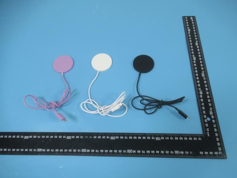
Click to zoom
Application Details
- Equipment Class
- DCD - Part 15 Low Power Transmitter Below 1705 kHz
- Date of Grant
- Sep 23, 2025
- Application Purpose
- Original Equipment
- Equipment Note
- 15W Magnetic Wireless Charger
- Frequency Range
- 0.11050000 - 0.20500000
- Company
- JEM ACCESSORIES INC.
- Country
- United States
Documents & Files
Document Text
Text extracted from the exhibit documents filed with the FCC. Open a document above to read the original.
Users Manual
Any Changes or modifications not expressly approved by the party responsible for compliance could void the user's authority to operate the equipment. This device complies with part 15 of the FCC Rules. Operation is subject to the following two conditions: (1) This device may not cause harmful interference, and (2) this device must accept any interference received, including interference that may cause undesired operation. Note: This equipment has been tested and found to comply with the limits for a Class B digital device, pursuant to part 15 of the FCC Rules. These limits are designed to provide reasonable protection against harmful interference in a residential installation. This equipment generates, uses and can radiate radio frequency energy and, if not installed and used in accordance with the instructions, may cause harmful interference to radio communications. However, there is no guarantee that interference will not occur in a particular installation. If this equipment does cause harmful interference to radio or television reception, which can be determined by turning the equipment off and on, the user is encouraged to try to correct the interference by one or more of the following measures: —Reorient or relocate the receiving antenna. —Increase the separation between the equipment and receiver. —Connect the equipment into an outlet on a circuit different from that to which the receiver is connected. —Consult the dealer or an experienced radio/TV technician for help. This equipment complies with FCC radiation exposure limits set forth for an uncontrolled environment. This equipment should be installed and operated with minimum distance 20cm between the radiator& your body. Model: PWC8-1040-BLK, PWC8-1040, PWC8-1040-WHT, PWC8-1040-PUR, XWC8-1043
Cover Letter(s)
JEM ACCESSORIES INC. Add: 32 Brunswick Avenue, Edison, New Jersey, United States,08817 Tel: +1 732-339-9800 Fax: +1 732-481-0300 E-mail: [email protected] Product Similarity Declaration FEDERAL COMMUNICATIONS COMMISSIONS Authorization and Evaluation Division 7435 Oakland Mills Road Columbia, MD 21046 To Whom It May Concern, We, JEM ACCESSORIES INC., hereby declare that we have a product named as 15W Magnetic Wireless Charger, (Model No.:PWC8-1040-BLK, FCC ID: 2AHAS-PWC81040M) was tested by Bay Area Compliance Laboratories Corp. (Shenzhen), meanwhile, for our marketing purpose, we would like to list a series models(PWC8-1040, PWC8-1040-WHT, PWC8-1040-PUR, XWC8-1043) on reports and certificate, all the models are identical in electrically, the difference as below. 1. Different Model No. 2. Different distributor. PWC8-1040, PWC8-1040-BLK, PWC8-1040-WHT, PWC8-1040-PUR have same distributor. PWC8-1040, PWC8-1040-BLK, PWC8-1040-WHT, PWC8-1040-PUR, XWC8-1043 have different distributor. 3. Different color. Model Color PWC8-1040-WHT White PWC8-1040-BLK Black PWC8-1040-PUR Purple PWC8-1040 Available in white, black, purple XWC8-1043 Factory own item No., Available in white We confirm that all information above is true, and we’ll be responsible for all the consequences. Please contact me if you have any question. Sincerely, Signature: Printed Name: Nathan Shamula Title: COO
External Photos
Bay Area Compliance Laboratories Corp. (Shenzhen) Report No.: 2501V00343E-RF-EXP Page 1 of 13 EXHIBIT B - EUT EXTERNAL PHOTOGRAPHS PWC8-1040-BLK Bay Area Compliance Laboratories Corp. (Shenzhen) Report No.: 2501V00343E-RF-EXP Page 2 of 13 Bay Area Compliance Laboratories Corp. (Shenzhen) Report No.: 2501V00343E-RF-EXP Page 3 of 13 Bay Area Compliance Laboratories Corp. (Shenzhen) Report No.: 2501V00343E-RF-EXP Page 4 of 13 PWC8-1040-PUR Bay Area Compliance Laboratories Corp. (Shenzhen) Report No.: 2501V00343E-RF-EXP Page 5 of 13 Bay Area Compliance Laboratories Corp. (Shenzhen) Report No.: 2501V00343E-RF-EXP Page 6 of 13 Bay Area Compliance Laboratories Corp. (Shenzhen) Report No.: 2501V00343E-RF-EXP Page 7 of 13 PWC8-1040-WHT Bay Area Compliance Laboratories Corp. (Shenzhen) Report No.: 2501V00343E-RF-EXP Page 8 of 13 Bay Area Compliance Laboratories Corp. (Shenzhen) Report No.: 2501V00343E-RF-EXP Page 9 of 13 Bay Area Compliance Laboratories Corp. (Shenzhen) Report No.: 2501V00343E-RF-EXP Page 10 of 13 XWC8-1043 Bay Area Compliance Laboratories Corp. (Shenzhen) Report No.: 2501V00343E-RF-EXP Page 11 of 13 Bay Area Compliance Laboratories Corp. (Shenzhen) Report No.: 2501V00343E-RF-EXP Page 12 of 13 Bay Area Compliance Laboratories Corp. (Shenzhen) Report No.: 2501V00343E-RF-EXP Page 13 of 13 PWC8-1040
ID Label/Location Info
Bay Area Compliance Laboratories Corp. (Shenzhen) Project No.: 2501V00343E-RF EXHIBIT A - FCC ID LABEL AND LOCATION FCC ID Label FCC ID Label Location Information The label shown shall be permanently affixed at a conspicuous location on the device and be readily visible to the user at the time purchase (Labeling requirements per 2.925)
Internal Photos
Bay Area Compliance Laboratories Corp. (Shenzhen) Report No.: 2501V00343E-RF-INP Page 1 of 3 EXHIBIT C - EUT INTERNAL PHOTOGRAPHS Bay Area Compliance Laboratories Corp. (Shenzhen) Report No.: 2501V00343E-RF-INP Page 2 of 3 ant Bay Area Compliance Laboratories Corp. (Shenzhen) Report No.: 2501V00343E-RF-INP Page 3 of 3
RF Exposure Info
Bay Area Compliance Laboratories Corp. (Shenzhen) Report No.: 2501V00343E-RF-00 TR-EM-RF034 Page 15 of 32 Version 3.0 FCC §2.1091 - MAXIMUM PERMISSIBLE EXPOSURE (MPE) Applicable Standard According to subpart §1.1310, systems operating under the provisions of this section shall be operated in a manner that ensures that the public is not exposed to radio frequency energy level in excess of the Commission’s guidelines. Limits for Maximum Permissible Exposure (MPE) (B) Limits for General Population/Uncontrolled Exposure Frequency Range (MHz) Electric Field Strength (V/m) Magnetic Field Strength (A/m) Power Density (mW/cm 2 ) Averaging Time (minutes) 0.3–1.34 614 1.63 *(100) 30 1.34–30 824/f 2.19/f *(180/f²) 30 30–300 27.5 0.073 0.2 30 300–1500 / / f/1500 30 1500–100,000 / / 1.0 30 f = frequency in MHz; * = Plane-wave equivalent power density; According with 680106 D01 Wireless Power Transfer v04 clause 3.2 Accordingly, for § 2.1091-Mobile devices, the MPE limits between 100 kHz to 300 kHz are to be considered the same as those at 300 kHz in Table 1 of § 1.1310, that is, 614 V/m and 1.63 A/m, for the electric field and magnetic field, respectively. For § 2.1093-Portable devices below 4 MHz and down to 100 kHz, the MPE limits in § 1.1310 (with the 300 kHz limit applicable all the way down to 100 kHz) can be used for the purpose of equipment authorization in lieu of SAR evaluations. There might be situations where the WPT RF emissions are limited enough that even operations in a “crowded” environment, where many similar WPT devices are present, do not pose significant EMC and RF exposure concerns. In this scenario, and for devices operating within a one-meter distance from the receiver, as defined above, a manufacturer will not have to submit an “Equipment Compliance Review” KDB, and receive FCC concurrence before proceeding with equipment authorization. This exception to the requirement of submitting the ECR to obtain FCC concurrence only applies when all the following criteria (1) through (6) are met: (1)The power transfer frequency is below 1 MHz. (2) The output power from each transmitting element (e.g., coil) is less than or equal to 15 watts. (3) A client device providing the maximum permitted load is placed in physical contact with the transmitter (i.e., the surfaces of the transmitter and client device enclosures need to be in physical contact) (4) Only § 2.1091-Mobile exposure conditions apply (i.e., this provision does not cover § 2.1093- Portable exposure conditions). (5) The E-field and H-field strengths, at and beyond 20 cm surrounding the device surface, are demonstrated to be less than 50% of the applicable MPE limit, per KDB 447498, Table 1. These measurements shall be taken along the principal axes of the device, with one axis oriented along the direction of the estimated maximum field strength, and for three points per axis or until a 1/d (inverse distance from the emitter structure) field strength decay is observed. Symmetry considerations may be used for test reduction purposes. The device shall be operated in documented worst-case compliance scenarios (i.e., the ones that lead to the maximum field components), and while all the radiating structures (e.g., coils or antennas) that by design can simultaneously transmit are energized at their nominal maximum power. (6) For systems with more than one radiating structure, the conditions specified in (5) must be met when the system is fully loaded (i.e., clients absorbing maximum power available), and with all the radiating structures operating at maximum power at the same time, as per design conditions. If the design allows one or more radiating structures to be powered at a higher level while other radiating Bay Area Compliance Laboratories Corp. (Shenzhen) Report No.: 2501V00343E-RF-00 TR-EM-RF034 Page 16 of 32 Version 3.0 structures are not powered, then those cases must be tested as well. For instance, a device may use three RF coils powered at 5 W, or one coil powered at 15 W: in this case, both scenarios shall be tested. Block Diagram of Test Setup Test Procedures 1) Perform H-field and E-field measurements for each all sides of the EUT at 20cm, along all the principal axes defined with respect to the orientation of the transmitting element (e.g., coil or antenna). 2) The highest emission level was recorded and compared with limit. 3) The EUT was measured according to 680106 D01 Wireless Power Transfer v04. Test Data Environmental Conditions Temperature: 27.6 °C Relative Humidity: 54 % ATM Pressure: 98.9 kPa The testing was performed by Rainbow Zhu on 2025-07-28. Test mode: Wireless charging (Maximum output power) 20cm Bay Area Compliance Laboratories Corp. (Shenzhen) Report No.: 2501V00343E-RF-00 TR-EM-RF034 Page 17 of 32 Version 3.0 H-Field Strength Test Frequency (KHz) Position A (A/m) Position B (A/m) Position C (A/m) Position D (A/m) Position E (A/m) Position F (A/m) 50% Limit (A/m) Limit (A/m) 110.5~205 0.00904 0.00522 0.00980 0.01 0.01 0.03 0.815 1.63 E-Field Strength Test Frequency (KHz) Position A (V/m) Position B (A/m) Position C (A/m) Position D (V/m) Position E (V/m) Position F (V/m) 50% Limit (A/m) Limit (V/m) 110.5~205 1.39 1.41 1.65 0.79 2.66 0.90 307 614 Note: Test with 20cm distance from the center of the probe(s) to the edge of the device. (1) The power transfer frequency is below 1 MHz. The operation frequency is 110.5~205 kHz. (2) The output power from each transmitting element (e.g., coil) is less than or equal to 15 watts. The maximum output power is 15 watts. (3) A client device providing the maximum permitted load is placed in physical contact with the transmitter (i.e., the surfaces of the transmitter and client device enclosures need to be in physical contact) The load is physical contact with the EUT. (4) Only § 2.1091-Mobile exposure conditions apply (i.e., this provision does not cover § 2.1093- Portable exposure conditions). The EUT is used in the mobile exposure condition. (5) The E-field and …
Text truncated - open the document above for the full version.
Test Report
Note: The information marked # is provided by the applicant, the laboratory is not responsible for its authenticity and this information can affect the validity of the result in the test report. Customer model name, addresses, names, trademarks etc. are included. This report cannot be reproduced except in full, without prior written approval of the Company. Unless otherwise stated the results shown in this test report refer only to the sample(s) tested. This report is valid only with a valid digital signature. The digital signature may be available only under the Adobe software above version 7.0. This report must not be used by the customer to claim product certification, approval, or endorsement by NVLAP or any agency of the U.S. Government. This report may contain data that are not covered by the NVLAP accreditation and are marked with an asterisk “▼”. Bay Area Compliance Laboratories Corp. (Shenzhen) 5F(B-West) , 6F, 7F, the 3rd Phase of Wan Li Industrial Building D, Shihua Rd, FuTian Free Trade Zone, Shenzhen, China Tel: +86-755-33320018 Fax: +86-755-33320008 www.baclcorp.com.cn TR-EM-RF034 Page 1 of 32 Version 3.0 TEST REPORT Applicant Name: JEM ACCESSORIES INC. Address: 32 Brunswick Avenue, Edison, New Jersey, United States, 08817 Report Number: 2501V00343E-RF-00 FCC ID: 2AHAS-PWC81040M Test Standard (s) FCC Part 15C Sample Description Product Type: 15W Magnetic Wireless Charger Model No.: PWC8-1040-BLK Multiple Model(s) No.: PWC8-1040, PWC8-1040-WHT, PWC8-1040-PUR, XWC8-1043 Trade Mark: N/A Date Received: 2025/07/21 Issue Date: 2025/09/16 Test Result: Pass ▲ ▲ In the configuration tested, the EUT complied with the standards above. Prepared and Checked By: Approved By: Bruce Lin Nancy Wang RF Engineer RF Supervisor Bay Area Compliance Laboratories Corp. (Shenzhen) Report No.: 2501V00343E-RF-00 TR-EM-RF034 Page 2 of 32 Version 3.0 TABLE OF CONTENTS DOCUMENT REVISION HISTORY ......................................................................................................................... 3 GENERAL INFORMATION ....................................................................................................................................... 4 PRODUCT DESCRIPTION FOR EQUIPMENT UNDER TEST (EUT) ..................................................................................... 4 OBJECTIVE ................................................................................................................................................................... 4 TEST METHODOLOGY .................................................................................................................................................. 4 MEASUREMENT UNCERTAINTY .................................................................................................................................... 5 TEST FACILITY ............................................................................................................................................................. 5 SYSTEM TEST CONFIGURATION .......................................................................................................................... 6 DESCRIPTION OF TEST CONFIGURATION ...................................................................................................................... 6 EUT EXERCISE SOFTWARE .......................................................................................................................................... 6 LOCAL SUPPORT EQUIPMENT ....................................................................................................................................... 6 EXTERNAL I/O CABLE .................................................................................................................................................. 6 BLOCK DIAGRAM OF TEST SETUP ................................................................................................................................ 7 SUMMARY OF TEST RESULTS ............................................................................................................................... 8 TEST EQUIPMENT LIST ........................................................................................................................................... 9 FCC§15.203 - ANTENNA REQUIREMENT ............................................................................................................ 10 APPLICABLE STANDARD ............................................................................................................................................ 10 ANTENNA CONNECTED CONSTRUCTION .................................................................................................................... 10 FCC §15.207 - AC LINE CONDUCTED EMISSION .............................................................................................. 11 APPLICABLE STANDARD ............................................................................................................................................ 11 EUT SETUP ................................................................................................................................................................ 11 EMI TEST RECEIVER SETUP ....................................................................................................................................... 11 TEST PROCEDURE ...................................................................................................................................................... 12 FACTOR & OVER LIMIT CALCULATION ...................................................................................................................... 12 TEST DATA ................................................................................................................................................................ 12 FCC §2.1091 - MAXIMUM PERMISSIBLE EXPOSURE (MPE) ........................................................................…
Text truncated - open the document above for the full version.
Test Setup Photos
Bay Area Compliance Laboratories Corp. (Shenzhen) Report No.: 2501V00343E-RF-TSP Page 1 of 6 EXHIBIT D - TEST SETUP PHOTOGRAPHS Conducted Emissions - Front View Conducted Emissions - Side View Bay Area Compliance Laboratories Corp. (Shenzhen) Report No.: 2501V00343E-RF-TSP Page 2 of 6 Radiated Emissions View (Below 30MHz) - Perpendicular Radiated Emissions View (Below 30MHz) - Parallel Bay Area Compliance Laboratories Corp. (Shenzhen) Report No.: 2501V00343E-RF-TSP Page 3 of 6 Radiated Emissions View (Below 30MHz) - Ground-parallel Radiated Emissions View (Below 1 GHz) Bay Area Compliance Laboratories Corp. (Shenzhen) Report No.: 2501V00343E-RF-TSP Page 4 of 6 A Position B Position Bay Area Compliance Laboratories Corp. (Shenzhen) Report No.: 2501V00343E-RF-TSP Page 5 of 6 C Position D Position Bay Area Compliance Laboratories Corp. (Shenzhen) Report No.: 2501V00343E-RF-TSP Page 6 of 6 E Position F Position
Contact Information
Applicant
Nathan Shamula
[email protected]Fax: 7324810300
Test Firm
Bay Area Compliance Laboratories Corp (Shenzhen)Nana Liu
Technical Specifications
| # | Rule Parts | Frequency Range | Power Output |
|---|---|---|---|
| 1 | 15C | 0.1105 MHz - 0.205 MHz | - |
Other Applications from JEM ACCESSORIES INC.
2AHAS-MBL11010P
Sep 14, 2026PARTY SPEAKER
Equipment Class
DSS - Part 15 Spread Spectrum Transmitter
2AHAS-XBS91087B
Sep 10, 202640W BT LED SPEAKER
Equipment Class
DSS - Part 15 Spread Spectrum Transmitter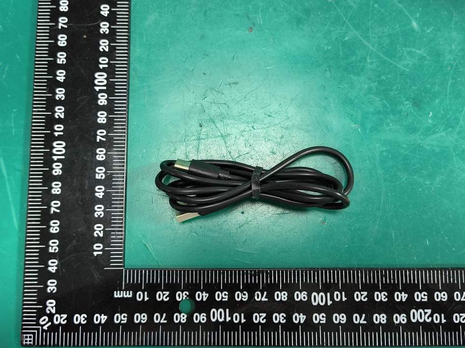
2AHAS-XWC81051T
Aug 21, 202615W Magnetic Phone Charger
Equipment Class
DCD - Part 15 Low Power Transmitter Below 1705 kHz2AHAS-PFM31003D
Aug 18, 2026Wireless FM Transmitter and Car Charger
Equipment Class
DSS - Part 15 Spread Spectrum Transmitter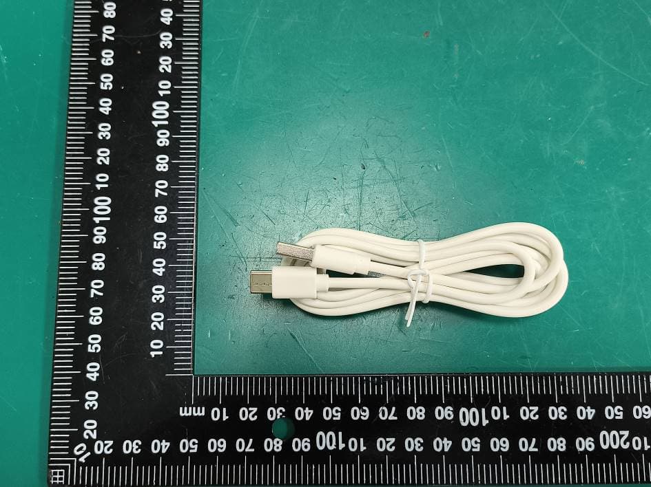
2AHAS-EOX11004J
Aug 13, 20262K outdoor cam streaming
Equipment Class
NII - Unlicensed National Information Infrastructure TX