2AHIR-003Smart home multi sensor for Z-Wave systems
Sensative AB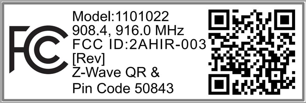
Click to zoom
Application Details
- Equipment Class
- DXX - Part 15 Low Power Communication Device Transmitter
- Date of Grant
- Feb 23, 2020
- Application Purpose
- Original Equipment
- Date of Application
- Feb 23, 2020
- Equipment Note
- Smart home multi sensor for Z-Wave systems
- Frequency Range
- 908.40000000 - 916.00000000
- Company
- Sensative AB
- Country
- Sweden
Documents & Files
Document Text
Text extracted from the exhibit documents filed with the FCC. Open a document above to read the original.
Users Manual
STRIPS 700: LIMITED WARRANTY ENGLISH US/INS 00 001 PRODUCT /WARRANTY/WARRANTY PERIOD/DEFECT: Sensative AB (”Company”) warrants to the original end-user purchaser (“Purchaser”) that Strips (“Product”) will be free from substantial defects in material and workmanship from the date when the Product is delivered to the Purchaser and continues for twelve (12) months thereafter (“Warranty period”). The information contained herein is provided to the Purchaser as a convenience. LIMITATION OF PRODUCT WARRANTY: Company warrants that the Product under normal use is free from substantial defects in material and workmanship (“Defect”) during the Warranty Period, subject to a proper installation, operation and maintenance of the Product as set forth in the user manual and other documentation that may become available to the Purchaser from time to time at www.stripsbysensative.com (“User Manual”). Company does however not warrant that the Product will operate uninterrupted or error-free or that all deficiencies, errors, defects or non-conformities will be corrected. The Warranty extends only to Purchaser and is not transferable to anyone else. CLAIMS PROCEDURE: Warranty claims are handled at www.sensative.com. Note that warranty claims must be filed to the Company by the Purchaser within 30 days of the manifestation of the problem. EXCLUSIONS: The warranty shall not apply to problems or damages resulting from or related to: • mechanical and/or transport problems • external causes such as accidents, acts of God, disasters, weather conditions, air pollution, abuse, misuse, misapplication or any equipment that generates electrical disturbance of radio communication that violates FCC and other standard regulations • negligence, improper handling and failure to operate the Product according to the User Manual • operating and storage problems • electrical power and/or telecommunications • the network and/or other products in the network • accessories and/or attachments not recommended by Company and/or modifica- tions to the Product or its parts • failure to follow Company’s instructions relating to the Product’s use or installation and/or to fulfil the maintenance and servicing activities defined in the User Manual • cracks, fractures, cuts, abrasions, physical deformations caused by impact, falling and/or dropping the device or other object, improper use and/or not observing the User Manual • service performed by anyone who is not an authorized representative of Company • a Product or part that has been modified • a Product that is used commercially or for a commercial purpose • failure of goods or services not obtained from Company GENERAL TERMS: COMPANY DOES NOT AUTHORIZE ANY PERSON OR PARTY TO ASSUME OR CREATE FOR IT ANY OBLIGATIONS OR LIABILITY IN CONNECTION WITH THE PRODUCT EXCEPT AS SET FORTH HEREIN. THIS WARRANTY SHALL NOT APPLY TO ANY PRODUCT IF THE COMPANY’S SERIAL NUMBER HAS BEEN REMOVED OR DEFACED IN ANY WAY. COMPANY IS NOT RESPONSIBLE FOR ANY PROBLEM OR DAMAGE THAT OCCURS AS A RESULT OF PURCHASER’S FAILURE TO OBSERVE THE USER MANUAL EXCEPT AS EXPRESSLY SET FORTH IN THIS WARRANTY COMPANY MAKES NO OTHER WARRANTIES EXPRESSED OR IMPLIED INCLUDING ANY IMPLIED WARRANTIES OF MERCHANTABILITY AND FITNESS FOR A PARTICULAR PURPOSE AND WARRANTIES AGAINST HIDDEN OR LATENT DEFECTS. COMPANY EXPRESSLY DISCLAIMS ALL WARRANTIES NOT STATED IN THIS WARRANTY. ANY IMPLIED WARRANTIES THAT MAY BE IMPOSED BY STATUTORY LAW ARE LIMITED IN DURATION TO THE WARRANTY PERIOD HEREUNDER. IN NO EVENT SHALL COMPANY BE LIABLE FOR ANY LOSS OF DATA OR ANY INDIRECT, INCIDENTAL, PUNITIVE, SPECIAL OR CONSEQUENTIAL DAMAGES OR DAMAGES FOR LOSS OF PROFITS, REVENUE OR USE INCURRED BY PURCHASER OR ANY THIRD PARTY, WHETHER IN ACTION, IN CONTRACT, OR OTHERWISE EVEN IF ADVISED OF THE POSSIBILITY OF SUCH DAMAGE. COMPANY’S LIABILITY AND PURCHASER’S EXCLUSIVE REMEDY FOR ANY CAUSE OF ACTION ARISING IN CONNECTION WITH THE SALE OR USE OF THE PRODUCT WHETHER BASED ON NEGLIGENCE, STRICT LIABILITY, BREACH OF WARRANTY OR EQUITABLE PRINCIPLES IS EXPRESSLY LIMITED TO COMPANY’S OPTION OF REPLACEMENT OF OR REPAYMENT OF THE PRODUCT PRICE FOR THAT PORTION OF THE PRODUCTS WITH RESPECT TO WHICH DAMAGES ARE CLAIMED. TO THE EXTENT ALLOWED BY LOCAL LAW, THE REMEDIES IN THIS WARRANTY STATEMENT ARE PURCHASER’S SOLE AND EXCLUSIVE REMEDIES AGAINST COMPANY. THEY DO NOT HOWEVER AFFECT OR RESTRICT THE RIGHTS THAT PURCHASER MAY HAVE AGAINST THE DISTRIBUTOR, SERVICE PROVIDER AND/OR RETAILER. ALL CLAIMS OF ANY KIND ARISING IN CONNECTION WITH THE SALE OF THE PRODUCT SHALL BE DEEMED WAIVED UNLESS MADE IN WRITING TO THE COMPANY WITHIN 30 DAYS FROM COMPANY’S DELIVERY OR THE DATE FIXED FOR DELIVERY IN THE EVENT OF NON DELIVERY. 6. THE PRODUCT USES VERY STRONG NEODYMIUM MAGNETS WHICH CAN BE HAZARDOUS IF SWALLOWED. KEEP THIS PRODUCT AWAY FROM CHILDREN AT ALL TIMES 7. MAGNETS FOUND WITHIN THE PRODUCT CAN INTERFERE OR DAMAGE CERTAIN MAGNETIC MEDIA, INCLUDING BUT NOT LIMITED TO OPTICAL HARD DRIVES, TELEVISIONS, MAGNETIC STORAGE MEDIA, PACE-MAKERS AND OTHER SENSITIVE ELECTRONICS 8. DO NOT DISPOSE OF ELECTRICAL APPLIANCE AS UNSORTED MUNICIPAL WASTE USE SEPARATED COLLECTION FACILITIES INDUSTRY CANADA STATEMENTS: This device complies with Industry Canada licence-exempt RSS standard(s). Operation is subject to the following two conditions: (1) this device may not cause interference, and (2) this device must accept any interference, including interference that may cause undesired operation of the device. This equipment complies with the safety requirements for RF exposure in accordance with RSS-102 §2.5.2. This equipment must be installed and operated in accordance with the provided instructions and a minimum 20 cm spacing must be provided between the antenna and any person’s body during wireless modes of operation. INDUSTRY CANADA NOTICE: “This device complies with ISED’s licence-exempt RSSs. Operation is subject to the following two conditions: (1) This device may not cause interference…
Text truncated - open the document above for the full version.
Users Manual
StripsareZ-Wavemagnetsensorsthatcanbeaddedtoany certifiedZ-WavesystemandoperatewithanyZ-Wavedevice. Z-Wave is an international standardforwireless communication in smart homes and buildings enabling youto monitorand control yourhome remotely. Please followthe three steps in this guideto get started. 1.Add2. Plan3. Place AB Forgood functionality inthe doororwindow • To place Strips invisibly, you need a gap with a minimum height of3.5 mm. •Strips may be mounted ontheframe (recommended) and the magnet on the door/window, or vice versa. • Check that magnet (A)can be placed so that it is less than 10 mm fromStrips’ flat endwhenthewindowis closed. Whenthewindowis open,the magnet should be at least 30 mm away fromStrips. • Open the door/window fullyto check that the placement of Strips and the magnet does not interfere with hinges or locking mechanisms. Tocorrectly mount Strips, please followthe steps below: 1. Make surethe surface is clean, dry and at least+10°C(+50°F) Use the included cloth to clean and prepare the surfaces. 2.Remove the short protective filmfromthe small Strips test adhesive.The small adhesive is used beforethefinal placement so it is easy to move Strips if needed. 3.Place Stripswhere you want it mounted. Check the position by carefully closing the door/window and then opening it completely again. 4.Measure and identify where the magnet (A) should be placed. Remove the protective film and place the magnet. Close and open again to validate that yourZ-Wave controller detected the changes. Re-mount if needed. 5.When you are satisfied, mark the exact position for Strips. Remove it from its position, ensure that the surface is still clean, remove the longfilm protectingthe adhesive backing and place Stripsexactly as you marked. The long adhesive is used to make thefinal placement of Strips. 6.Checkthatthe door/windowcan be fully closed and opened and that your Z-Wave controller detects the changes. 7.Keep the round magnet (B); since it can be used to wake up, remove or resetStrips in thefuture. More guidance including instructional videos: www.sensative.com/guard Strips GuardENGLISH AD D PLA N PL A C E Wake up To wake up Strips manually for Z-Wave communication, first place the round magnet (B) at the rounded edge. When the LED blinks, move the magnet away. Repeat a total of 3 timeswithin 10 seconds. Add/remove Set yourcontrollerin add orremove mode(see yourcontroller’s manual). Follow the instruction above for Wakeup. Along LED blink indicates that the add/remove was successful. Reset You may need to resetStrips ifyourZ-Wave controlleris missing ornot responding. Follow the instructionsfor “Wake up” above, but on the 3rd repetition, leave the magnet at the rounded edgefor 10 seconds. Along LED signal indicates success. 1 short blink •Userfeedback duringcommands • Specific event detected (e.g. door opened)* 2 shortIf Strips is not added 1 longUser command successfully executed 5 shortError. e.g. communication with controller failed NoDescriptionValuesDefault 1 Notification type (1 byte) 0: Binary Sensor report 1: Notification report 2: Basic report 1 2 LED indication (1 byte) 0: Specific event indication (*) Off 1: On 1 Strips are delivered in auto-add mode. Followthe process belowto add Stripsto yournetwork. 1. Start the add mode on your Z-Wave controller. See yourcontroller’s manual. 2.Keep Strips close to its intended location during the add process. Remove both magnets. 1 long blinkconfirms the addition. 3.YourZ-Wave controllerapplication should nowbe able to monitoryourStrips sensorstatus. 4.Move the squared magnet (A) away from the squared end. Checkthat yourZ-Wave system indicatesthe status correctly. 5.If your Z-Wave system doesn’t respond, you may need to changeStrips’ notification typefromthecontroller. Association Strips supports association group 1 (lifeline), max 1 node, normally used to send Strips’ statusto the Z-Wave controller. Tamper Strips will send a tamper alert if it detects that someone triesto wake up or manipulate Strips. GB/INS 11 01 022 R1 A ) LED LIGH T SIGNAL S B) C ONFIGUR A TION C) USER COMMAND S D) OTHE R P ARAMETER S
Attestation Statements
Company Internal1(1) Document numberRevision B Prepared byDate CEO Mats Pettersson2020-02-13 Contents responsible if other than preparerRemarks Approved by Differences letter for FCC ID: 2AHIR-003 The product certified under 2AHIR-003 will be available in several models based on what functionality that is enabled for that particular model. All models are based on the same generic product with same hardware and software. Model NumberFunctionality 1100022Generic version with all sensors mounted and enabled 1101022Magnet Sensor, for door window status 1102022Temperature, Ambient light, Air humidity sensor 1103022Magnet Sensor Pro, Including removal tamper alarm 1104022Water leakage detector, temperature sensor 1105022Temperature, ambient light sensor (outdoor) Design: The design separates the transceiver including radio protocol stack completely from the sensors by having a separate u-Controler and software for that functionality. This grantees that the transceiver is identical for all variants, down to PCB layout and radio protocol stack. u-Controller with sensorsTransceiver with antenna Declaration Sensative declare and guarantee that all model's under FCC ID 2AHIR-003 are identical in RF and EMC performance Sincerely, By:__________________________________________________ (Signature/Title)(Print name) Note: Any hard copy of this document is for reference only. Due to template and application dependencies the header and footer may fail to display correct data. It is the responsibility of the user to ensure that they have a correct and valid version. Any outdated hard copy is invalid and must be removed from possible use. CEO Mats Pettersson
Cover Letter(s)
Company Internal 1(1) Document number Revision A Prepared by Date CEO Mats Pettersson 2019-10-22 Contents responsible if other than preparer Remarks Approved by Note: Any hard copy of this document is for reference only. Due to template and application dependencies the header and footer may fail to display correct data. It is the responsibility of the user to ensure that they have a correct and valid version. Any outdated hard copy is invalid and must be removed from possible use. Authority to Act as Agent TUV Rheinland of North America, Inc. 1279 Quarry Ln., Ste. A Pleasanton, CA 94566 To Whom It May Concern: I appoint TUV Rheinland of North America, Inc to act as our agent in the preparation of this application for equipment certification. I certify that submitted documents properly describe the device or system for which equipment certification is sought. I also certify that each unit manufactured, imported or marketed, as defined in the FCC or Industry Canada’s regulations will have affixed to it a label identical to that submitted for approval with this application. For instances where our authorized agent signs the application for certification on our behalf, I acknowledge that all responsibility for complying with the terms and conditions for Certification, as specified by TUV Rheinland Group, still resides with Sensative AB, Mobilväge 10, 23 62 Lund, Sweden. For TCB applications, We certify that we are not subject to denial of federal benefits, that includes FCC benefits, pursuant to Section 5301 of the Anti-Drug Abuse Act of 1988, 21 U.S.C. 862. Further, no party, as defined in 47 CFR 1.2002 (b), to the application is subject to denial of federal benefits, that includes FCC benefits. Thank you, Agency Agreement Expiration Date: 2020-10-22 By: __________________________ Mats Pettersson Title: CEO Telephone: +46 705 100384 On behalf of: Sensative AB
Cover Letter(s)
Company Internal 1(1) Document number Revision A Prepared by Date CEO Mats Pettersson 2019-10-22 Contents responsible if other than preparer Remarks Approved by Note: Any hard copy of this document is for reference only. Due to template and application dependencies the header and footer may fail to display correct data. It is the responsibility of the user to ensure that they have a correct and valid version. Any outdated hard copy is invalid and must be removed from possible use. Confidentiality Request for FCC ID: 2AHIR-003 Pursuant to FCC 47 CRF 0.457(d) and 0.459 and IC RSP-100, Section 12.4, the applicant requests that a part of the subject FCC/IC application be held confidential. Type of Confidentiality Requested Exhibit Short Term Permanent Block Diagrams Short Term Permanent Internal Photos Short Term Permanent Operation Description/Theory of Operation Short Term Permanent Schematics Short Term Permanent User’s Manual Sensative AB has spent substantial effort in developing this product and it is one of the first of its kind in industry. Having the subject information easily available to "competition" would negate the advantage they have achieved by developing this product. Not protecting the details of the design will result in financial hardship. Permanent Confidentiality: The applicant requests the exhibits listed above as permanently confidential be permanently withheld from public review due to materials that contain trade secrets and proprietary information not customarily released to the public. Short-Term Confidentiality: The applicant requests the exhibits selected above as short term confidential be withheld from public view for a period of 90 days from the date of the Grant of Equipment Authorization and prior to marketing. This is to avoid premature release of sensitive information prior to marketing or release of the product to the public. Applicant is also aware that they are responsible to notify TUV Rheinland in the event information regarding the product or the product is made available to the public. TUV Rheinland will then release the documents listed above for public disclosure pursuant to FCC Public Notice DA 04-1705. Sincerely, By: __________________________ Mats Pettersson (Signature/Title) (Print name)
External Photos
Company Internal1(2) Document numberRevision A Prepared byDate CQO Lars Jonsson2020-01-14 Contents responsible if other than preparerRemarks This document is managed in Sensative Cloud storage (UI-Project or G-Drive) Approved by 2AHIR-003 External Photos Sensative Strip sensors Note: Any hard copy of this document is for reference only. Due to template and application dependencies the header and footer may fail to display correct data. It is the responsibility of the user to ensure that they have a correct and valid version. Any outdated hard copy is invalid and must be removed from possible use. Side view Company Internal2(2) Document numberRevision A Front side Back side Labels Statement in regards of FCC rule part §15.19 (5) Labeling requirements 1101012 is only 19,5 cm × 1,5 cm in size and is therefore smaller than the palm of the hand and, consequently, the appropriate labeling requirement of FCC rule part 15.19 is included in the User Manual instead of being on the product label 10 mm 30 mm 7 mm 23 mm
ID Label/Location Info
Company Internal1(2) Document numberRevision A Prepared byDate CQO Lars Jonsson2020-01-14 Contents responsible if other than preparerRemarks This document is managed in Sensative Cloud storage (UI-Project or G-Drive) Approved by 2AHIR-003 External Photos Sensative Strip sensors Note: Any hard copy of this document is for reference only. Due to template and application dependencies the header and footer may fail to display correct data. It is the responsibility of the user to ensure that they have a correct and valid version. Any outdated hard copy is invalid and must be removed from possible use. Side view Company Internal2(2) Document numberRevision A Front side Back side Labels Statement in regards of FCC rule part §15.19 (5) Labeling requirements 1101012 is only 19,5 cm × 1,5 cm in size and is therefore smaller than the palm of the hand and, consequently, the appropriate labeling requirement of FCC rule part 15.19 is included in the User Manual instead of being on the product label 10 mm 30 mm 7 mm 23 mm
Internal Photos
Company Internal1(2) Document numberRevision B Prepared byDate CQO Lars Jonsson2020-02-13 Contents responsible if other than preparerRemarks This document is managed in Sensative Cloud storage (UI-Project or G-Drive) Approved by 2AHIR-003 Internal Photos Sensative Strip sensors Note: Any hard copy of this document is for reference only. Due to template and application dependencies the header and footer may fail to display correct data. It is the responsibility of the user to ensure that they have a correct and valid version. Any outdated hard copy is invalid and must be removed from possible use. Company Internal2(2) Document numberRevision B Internal u-Controller with sensorsRadio TransceiverAntenna Internal with battery
RF Exposure Info
Produkte Products Prüfbericht-Nr.: 60328072-001 Test Report No.: Seite 2 von 5 Page 2 of 5 Revisions Revisions Revision Revision Datum Date Anmerkung Remark Verfasser Author 001 2019-12-19 First release Niall Forrester Note: Latest revision report will replace all previous reports TABLE OF CONTENTS Table of Contents ................................................................................................................... 2 Product Information ................................................................................................................ 3 1.1 Equipment under Test (EUT) description ............................................................................................... 3 1.2 Wireless Technologies and Frequency Bands supported by the DUT .................................................. 3 1.3 Conducted Power and Antenna Gain ..................................................................................................... 3 Evaluation .............................................................................................................................. 3 2.1 Summary ................................................................................................................................................ 3 2.2 Limits ...................................................................................................................................................... 4 2.3 Stand-alone Calculations ....................................................................................................................... 5 Produkte Products Prüfbericht-Nr.: 60328072-001 Test Report No.: Seite 3 von 5 Page 3 of 5 PRODUCT INFORMATION 1.1 Equipment under Test (EUT) description Model name: Strip Sensor Manufacturer: Sensative AB Model number: 1100022/1101022/1102022/1103022/1104022/1105022/1106022 FCC ID: FCC ID: 2AHIR-003 Description: Strips by Sensative is in its basic version a magnetic sensor designed to monitor and protect windows, doors and other valuables. 1.2 Wireless Technologies and Frequency Bands supported by the DUT Technology Band Frequency Range (Tx) Evaluation Performed Z-Wave 908MHz 908.20 – 908.60 MHz YES Z-Wave 916MHz 915.85 – 916.15 MHz YES The device does not support any simultaneous transmission configurations 1.3 Conducted Power and Antenna Gain Technology Band Maximum Conducted Output Power (dBm) Antenna Gain (dBi) Z-Wave 908MHz 1.00 2.30 Z-Wave 916MHz 1.00 2.30 Maximum Power and Antenna Gain are based on details supplied by the device manufacturer. EVALUATION 2.1 Summary At 20cm, the Strip Sensor device(s) with FCC ID: 2AHIR-003 is compliant with the “General Population / Uncontrolled” requirements set out in FCC 47 CFR §1.1310 Table 1 (B) for all supported combinations of wireless technologies. Produkte Products Prüfbericht-Nr.: 60328072-001 Test Report No.: Seite 4 von 5 Page 4 of 5 2.2 Limits 47 CFR § 1.1310 - Radiofrequency radiation exposure limits Table 1B Limits for Maximum Permissible Exposure (MPE) (Limits for general Population / Uncontrolled Exposure) Frequency Range (MHz) Electric Field strength (V/m) Magnetic Field strength (A/m) Power Density (mW/cm 2 ) Averaging Time (minutes) 0.3 - 1.34 614 1.63 *100 30 1.34 - 30 824/f 2-19/f *180/f 2 30 30 - 300 27.5 0.073 0.2 30 300 - 1500 - - f/1500 30 1500 - 10000 - - 1.0 30 Notes: 1. ƒ = frequency in MHz 2. * = Plane-wave equivalent power density Produkte Products Prüfbericht-Nr.: 60328072-001 Test Report No.: Seite 5 von 5 Page 5 of 5 2.3 Stand-alone Calculations The Power Density at 20cm separation distance has been calculated for each of the transmitter technologies supported by the device according to a re-arrangement of the Friis formula, as below: 푆= 푃∗퐺 4휋∗푟² Where: “S” is power density in mW/cm² “P” is maximum avg. conducted power (incl. tolerances) in mW according to data from the manufacturer “G” is the peak antenna gain (numerical) according to data from the manufacturer “r” is the separation distance (20 cm) Power Density (S) at 20cm Distance for Each Transmitter Technology Band Frequency (MHz)* Power (dBm) P (mW) Gain (dBi) G (Num.) r (cm) S (mW/cm 2 ) Limit** (mW/cm 2 ) Z-Wave 908MHz 908.2 1.00 1.26 2.30 1.70 20 0.004 0.605 Z-Wave 916MHz 915.85 1.00 1.26 2.30 1.70 20 0.004 0.611 *The lowest frequency in each band has been chosen, to give the most conservative limit **The limits listed are from FCC 47 CFR §1.1310 Table 1 (B): “Limits for General Population/Uncontrolled” From 300MHz to 1500MHz, the limit is f/1500 mW/cm 2 where “f” is the frequency in MHz
Test Report
Produkte Products Prüfbericht-Nr.: 60335508-002 Test Report No.: Seite 2 von 40 Page 2 of 40 Revisions Revisions Revision Revision Datum Date Anmerkung Remark Verfasser Author 001 2020-02-04 First Release Fariborz Abasi 002 2020-02-13 Band edge plots updated with 50 dB limit info and editorial corrections Fariborz Abasi Note: Latest revision report will replace all previous reports Produkte Products Prüfbericht-Nr.: 60335508-002 Test Report No.: Seite 3 von 40 Page 3 of 40 Summary of Test Results FCC Rule Part Test item Result Remarks 15.203 Antenna requirements Pass Integrated antenna Antenna gain: 2.3 dBi 15.249(a) Transmitter Fundamental Field Strength Pass 15.215 (c) 20 dB Bandwidth Pass 15.249(a)(d)(e) 15.209(a) Transmitter Radiated Emissions Pass 15.249(d) / 15.209(a) Transmitter Band Edge Radiated Emissions Pass Possible test case verdicts: - test case does not apply to the test object ....: N/A - test object does meet the requirement ..........: PASS - test object does not meet the requirement ....: FAIL - test case not performed on the test object ....: n.p. Produkte Products Prüfbericht-Nr.: 60335508-002 Test Report No.: Seite 4 von 40 Page 4 of 40 Table of contents 1 Test Sites ................................................................................................................................... 5 2 Product Information .................................................................................................................... 6 2.1 General description ............................................................................................................................................. 6 2.2 Radio specific details .......................................................................................................................................... 6 2.3 Equipment Under Test (EUT) identification ........................................................................................................ 7 2.4 Ancillary equipment for verification purposes ..................................................................................................... 7 3 Test Methods and Operation Modes .......................................................................................... 8 3.1 Test Methods ...................................................................................................................................................... 8 3.2 EUT Operation modes ........................................................................................................................................ 8 4 Test Results - Transmitter Fundamental Field Strength ............................................................. 9 4.1 Transmitter Fundamental field strength – Test summary ................................................................................... 9 4.2 Transmitter Fundamental field strength – Test Setup ........................................................................................ 9 4.3 Transmitter Fundamental field strength – Test details ....................................................................................... 9 5 Test Results - Transmitter 20 dB Bandwidth ............................................................................ 10 5.1 Transmitter 20 dB Bandwidth – Test summary ................................................................................................ 10 5.2 Transmitter 20 dB Bandwidth – Test setup ...................................................................................................... 11 5.3 Transmitter 20 dB Bandwith – Test details ....................................................................................................... 11 6 Test Results - Radiated emissions ........................................................................................... 14 6.1 Radiated emissions - Test summary ................................................................................................................ 14 6.2 Radiated Emissions - Chamber setup .............................................................................................................. 16 6.3 Radiated Emissions – Test result details .......................................................................................................... 18 7 Transmitter Band Edge Radiated Emissions ............................................................................ 35 7.1 Transmitter Band Edge Radiated Emissions – Test summary ......................................................................... 35 7.2 Transmitter Band Edge Radiated Emissions – Test Setup .............................................................................. 35 7.3 Transmitter Band Edge Radiated Emissions – Test details ............................................................................. 35 8 Test Equipment List ................................................................................................................. 39 8.1 Radiated Emission SAC 5 chamber ................................................................................................................. 39 8.2 20 dB Bandwidth ............................................................................................................................................... 40 9 Measurement uncertainty ......................................................................................................... 40 9.1 Radiated Emission SAC 5 ................................................................................................................................ 40 9.2 20 dB Bandwidth ............................................................................................................................................... 40 Produkte Products Prüfbericht-Nr.: 60335508-002 Test Report No.: Seite 5 von 40 Page 5 of 40 1 TEST SITES Testing facility TÜV Rheinland Sweden AB Mobilvägen 10 223 62 Lund Sweden FCC Test Firm Registration Number: 517458 P…
Text truncated - open the document above for the full version.
Test Setup Photos
Produkte Products Prüfbericht-Nr.: 60335508-002 Appendix 1 Test Report No.: Seite 1 von 9 Page 1 of 9 1 APPENDIX 1 – TEST SETUP PHOTOS 1.1 Radiated Emissions Photos 1.1.1 Test setup for 9 KHz – 30 MHz (Prependicular to axis) Produkte Products Prüfbericht-Nr.: 60335508-002 Appendix 1 Test Report No.: Seite 2 von 9 Page 2 of 9 1.1.2 Test setup for 9 KHz – 30 MHz (Parallel to axis) Produkte Products Prüfbericht-Nr.: 60335508-002 Appendix 1 Test Report No.: Seite 3 von 9 Page 3 of 9 1.1.1 Test setup for 9 KHz – 30 MHz (Parallel to floor) Produkte Products Prüfbericht-Nr.: 60335508-002 Appendix 1 Test Report No.: Seite 4 von 9 Page 4 of 9 1.1.2 Test setup for 30 MHz – 1 GHz Produkte Product…
Text truncated - open the document above for the full version.
Contact Information
Applicant
Lars Jonsson
Technical Contact
Test Firm
TUV Rheinland Sweden ABPer Isacsson
[email protected]+46769498029
Technical Specifications
| # | Rule Parts | Frequency Range | Power Output |
|---|---|---|---|
| 1 | 15C | 908.4 MHz - 916 MHz | - |
Other Applications from Sensative AB
2AHIR-005
Aug 22, 2024Compact Indoor/Outdoor asset tracker, Air pressure sensor (enabling 3D positioning), Motion controlled.
Equipment Class
DSS - Part 15 Spread Spectrum Transmitter