2AHJWSENTIO1Bone Anchored Hearing System
Oticon Medical AB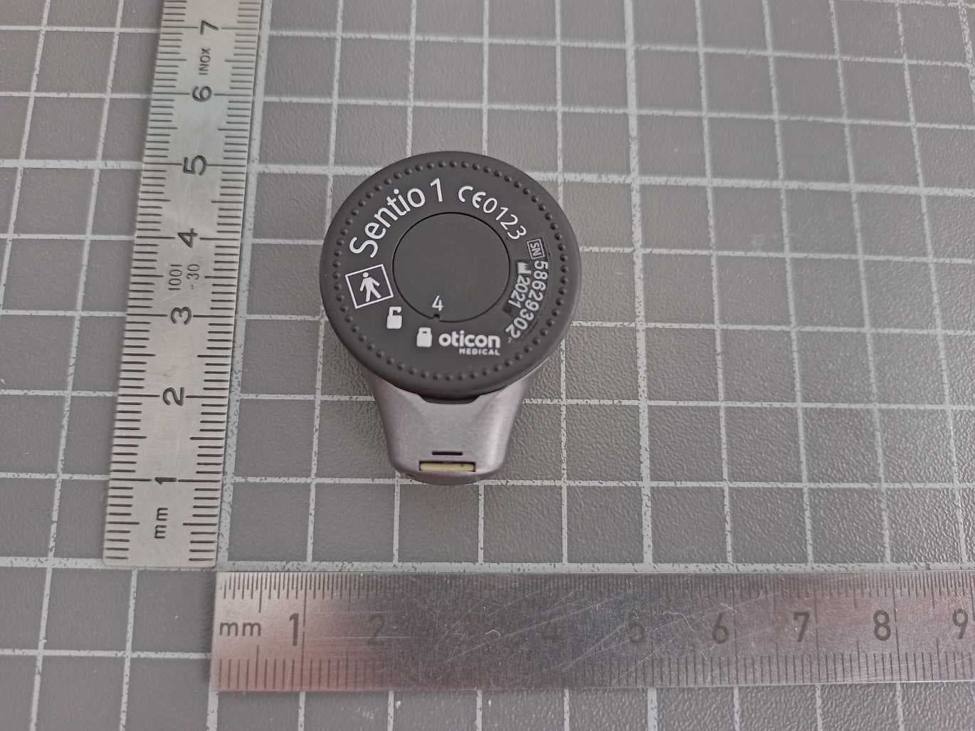
Click to zoom
Application Details
- Equipment Class
- DTS - Digital Transmission System
- Date of Grant
- Dec 18, 2022
- Application Purpose
- Original Equipment
- Date of Application
- Dec 18, 2022
- Equipment Note
- Bone Anchored Hearing System
- Frequency Range
- 2402.00000000 - 2480.00000000
- Company
- Oticon Medical AB
- Country
- Sweden
Documents & Files
Document Text
Text extracted from the exhibit documents filed with the FCC. Open a document above to read the original.
Users Manual
Sentio 1 Mini Instructions for Use Sound processor 3 The Instructions for Use The Sentio System is intended for improvement of hearing for patients with conduc- tive and mixed hearing losses by unilateral or bilateral fitting, and single sided deafness. The system comprises of an implant and an externally worn sound proces- sor. The implant is placed fully under the skin and the sound processor is retained to the implant site with a magnet. The Sentio 1 Mini sound processor is designed to be optimised for each individual per- son. This will help ensuring you get the maximum benefit from your sound processor. The Sentio 1 Mini sound processor is intended for use in homes, hospitals, health care institutions as well as in public environments. However, make sure that cautions related to specific situations mentioned in the “Important Information” and the “Warnings” sections are considered. The Instructions for Use gives you guidance on how to use and maintain your new sound processor. 4 Please read through this manual carefully to learn how to get the most out of your sound processor. Pay extra attention to Warnings section, Important information, Skin care and retention comfort and Sound Processor maintenance. Discuss any questions or concerns with your hearing care professional. Summary of Safety and Clinical Performance (SSCP) report for the Sentio System is publicly available in the EUDAMED database. 1 1 https://ec.europa.eu/tools/eudamed. Entering key Sentio 1 Mini sound processor: Basic UDI-DI: 57121491001185 Entering key Sentio Ti Implant: Basic UDI-DI: 57121491001083 5 The Instructions for Use ......................................................................................3 In the box ...........................................................................................................8 Processor view ...................................................................................................9 The Sentio 1 bone conduction hearing system ...................................................10 Switching the sound processor ON and OFF ......................................................12 When to replace the battery ...............................................................................13 How to replace the battery ................................................................................14 Left or right marking ..........................................................................................17 Connection ......................................................................................................18 Disconnection .................................................................................................18 Correct position ...............................................................................................18 Skin care and retention comfort ........................................................................20 Sound processor maintenance .........................................................................21 Optional features and accessories ....................................................................22 Safety line .......................................................................................................22 Volume control ................................................................................................24 Programmes ....................................................................................................25 Mute ................................................................................................................26 Flight mode .....................................................................................................27 6 Use the sound processor with iPhone and iPad .................................................28 Pairing the sound processor with iPhone ...........................................................29 Wireless accessories.........................................................................................31 Sentio 1 compatible with the following articles ..................................................32 Service and repair ............................................................................................33 Manufacturer’s warranty ...................................................................................34 Common problems and their possible solutions ................................................35 Important information ......................................................................................37 Regulatory compliance statements ....................................................................38 Warnings ..........................................................................................................41 Symbol clarifications ........................................................................................49 Sound and LED light indicators .........................................................................52 7 8 In the box • Sentio 1 Mini sound processor • Sentio 1 Mini case • Batteries (size 675) • Safety line • Left/right indication (blue/red) • Tamper resistant battery lid tool 9 LED (light diode) Microphone inlets Magnet Processor view Hole for Safety line Warning: The sound processor contains small parts that may be a choking hazard for small children. Batteries can also be harmful if swallowed. Always keep batteries out of reach of small children or people of diminished mental capacity. If a sound processor is accidentally swallowed, seek medical attention at the nearest emergency department. Push button Battery lid Hole for TAR Hole for TAR 10 The Sentio bone conduction hearing system Your Sentio 1 Mini sound processor is designed to help you gain improved hearing through direct bone conduction. The sound processor converts sound into signals which are transmitted to the Sentio Ti Implant where they are converted into vibra- tions. The vibrations pass through the skull bo…
Text truncated - open the document above for the full version.
Cover Letter(s)
Document Version 1.1 2020-10-30 LONG-TERM CONFIDENTIALITY REQUEST for Certification Service in the USA Federal Communication Commission Equipment Authorization Division, Application Processing Branch 7435 Oakland Mills Road Columbia, MD 21048 TO WHOM IT M AY CONCERN Pursuant to Paragraphs §0.457 and 0.459 of the Commission’s Rules (47 C.F.R.) and Section §552(b)(4) of the Freedom of Information Act, we request Long-Term Confidentiality for the following product: For the product stated above, we request Long-Term Confidentiality for exhibits which contain Block Diagram, Operational Description, Parts List/Tune Up Info, Schematics, SDR Software/Security Info. The above exhibits contain ou r trade secrets and proprietary information that could be of benefit to o ur competitors. This information will not be publicly available. If you have any questions, please feel free to contact us at the address shown below. Sincerely, Company Name: Phone: Company Address: Fax: E-mail: Contact Name: Signature: Signature Date: Check your GC here. Click Grantee Search. FCC I D: Grantee Code Equipment Product Code
External Photos
Annex A 1-3819/22-01-01_AnnexA External photos of the Equipment Under Test This addendum is electronically signed and valid without handwritten signature. For verification of the electronic signatures, the public keys can be requested at the testing laboratory. Document authorized: Michael Dorongovski Lab Manager Radio Communications CTC advanced GmbHUntertuerkheimer Str. 6-10 66117 Saarbruecken / Germany Phone: +49 681 5 98 - 0 Fax: +49 681 5 98 - 9075 web: ctcadvanced.com e-mail: [email protected] Photos Photo 1 Photo 2 2022-10-21Document No. 1-3819/22-01-01_AnnexA2/4 Photo 3 Photo 4 2022-10-21Document No. 1-3819/22-01-01_AnnexA3/4 Document history VersionApplied changesDate of release initial release2022-10-21 - END OF DOCUMENT - 2022-10-21Document No. 1-3819/22-01-01_AnnexA4/4
ID Label/Location Info
2022-11-09 Manufacturer’s Statement FCC ID location justification FCC ID: 2AHJWSENTIO1 TO WHOM IT MAY CONCERN We, the undersigned, hereby submit the justification for placing the FCC ID in the Associated User Manual for the Bone Anchor Hearing System having the above-mentioned FCC IDs. According to KDB Publication 784748 D01, when the device is so small, or for such use that it is impracticable to label with a font size that is four points or larger (and the device does not utilize electronic labelling), then the FCC ID shall be placed in the user manual. The Sound Processor part of the Bone Anchor Hearing System having the above-mentioned FCC IDs are so small and considering the dimensions of the equipment and the label area, it is impracticable to label FCC ID with a font size required on the devices. Therefore, the FCC ID label is placed in the User Manual. Yours sincerely, Per Klaus Nielsen Principal certification Specialist, Regulatory Affairs Oticon Medical
ID Label/Location Info
Sentio 1 Mini packaging label
Internal Photos
Sentio 1 PCB_Bottom_view Doc-00120245,Revision 0, Released Sentio 1 PCB_Top_view Doc-00120245,Revision 0, Released
RF Exposure Info
BNetzA - CAB - 02/21 - 102 SAR Test exclusion documentation according to FCC KDB 447498 Report identification number: 1-3819/22-01-15 Exclusion (FCC) contains the module with the following certification numbers FCC ID 2AHJWSENTIO1 This test report is electronically signed and valid without handwritten signature. For verification of the electronic signatures, the public keys can be requested at the testing laboratory. Document authorised: Alexander Hnatovskiy Marco Scigliano Lab Manager Testing Manager Radio Communications & EMC Radio Communications & EMC Test report no.: 1-3819/22-01-15 © CTC advanced GmbH Page 2 of 4 EUT technologies: Technologies: Max. declared cond. AVG Power Max. measured EIRP Antenna gain Proprietary 1) 120 kHz 11.47 dBm 3) (=14.04mW) 1.45 dBμV @30m (Peak) = -73.85 dBm < 0 dBi BT LE 2) 2450 -1.9 dBm (=0.65 mW) -- < 0 dBi NOTE: The measured PEAK EIRP @30m proofs that the EUT antenna gain is far below 0dBi and that considering the max. declared output power is by far larger than the EIRP. Conducted values will be used for the RF exposure calculation. EIRP values are for information only. 1) Test results taken from CTC advanced GmbH report 1-3819/22-01-06 (page 15): 1.45 dBμV/m @30m → EIRP: -73.85 dBm 2) BT LE conducted results taken from CTC advanced GmbH report 1-3819/22-01-03 (page 23): -1.9 dBm 3) Max declared conducted output power according customer declaration Collocation: Active scenario: Technology 1 2 3 4 Proprietary 120 kHz x x BT LE 2450 MHz x x Test report no.: 1-3819/22-01-15 © CTC advanced GmbH Page 3 of 4 SAR test exclusion according to KDB447498 (General RF Exposure Guidance v06) Equation from Chapter 4.3.1: Standalone SAR test exclusion considerations page 11 and ff. BT LE: (1) Standalone SAR test exclusion for 100 MHz to 6 GHz at test separation distances ≤ 50mm ( Threshold 1-g;10-g ) × d seperation / f 0.5 where Threshold 1-g;10-g is 3 for 1-g; 7.5 for 10-g d seperation is the min. test separation distance; 5mm is used if the distance is less f is the RF channel transmit frequency The table below gives the calculated maximal power that could be used for source based time averaged conducted or radiated power, adjusted for tune up tolerance. If this is at or below the calculated value the DUT is exempted from SAR evaluation. frequency d separation Powerlimit [MHz] [mm] [mW] [dBm] [mW] 2450.00 5 3 9.58 -1.90 0.65 yes Threshold 1-g Exclusion P max-declared NFC: (c) (2) Standalone SAR test exclusion below 100 MHz < 50mm 0.5 × (Threshold 100MHz ) × (1+log(100/f)) where Threshold 1-g;10-g is 3 for 1-g; 7.5 for 10-g f is the RF channel transmit frequency Threshold 100MHz,50mm is Threshold 1-g;10-g × d / f 0.5 ; with f = 100MHz and d=50mm The table below gives the calculated maximal power that could be used for source based time averaged conducted power, adjusted for tune up tolerance. If this is below the calculated value SAR testing is excluded. frequency Powerlimit [MHz] [mW] [dBm] [mW] 0.120 3 474.34 929.90 11.47 14.0 yes Threshold 100MHz,50mm P max-declared Exclusion Threshold1-g;10-g Test report no.: 1-3819/22-01-15 © CTC advanced GmbH Page 4 of 4 Collocation: Overview: Technology , [MHz] Proprietary, 120 kHz BT LE , 2450 MHz Exemption based on Limit EIRP [mW]: 929.9 9.58 Result EIRP [mW]: 14.0 0.65 Limit-Exhaustion [%] 1.5 6.8 Collocated percentage [%] [ Proprietary 120 kHz + BT LE ] Verdict: SAR exclusion 8.3 Pass This prediction demonstrates the following: The power density levels for FCC that are larger than the minimum safety-distances stated above, are below the maximum levels allowed by regulations.
Test Report
TEST REPORT Test report no.: 1-3819/22-01-0 3 Testing laboratory Applicant CTC advanced GmbH Untertuerkheimer Strasse 6 – 10 66117 Saarbruecken / Germany Phone: + 49 681 5 98 - 0 Fax: + 49 681 5 98 - 9075 Internet: https://www.ctcadvanced.com e-mail: [email protected] Accredited Testing Laboratory: The testing laboratory (area of testing) is accredited according to DIN EN ISO/IEC 17025 (2018-03) by the Deutsche Akkreditierungsstelle GmbH (DAkkS) The accreditation is valid for the scope of testing procedures as stated in the accreditation certificate starting with the registration number: D-PL-12076-01. Oticon Medical AB Datavägen 37B 43632 Askim / SWEDEN Phone: -/- Contact: Anja Ravn e-mail: [email protected] Manufacturer Oticon Medical AB Datavägen 37B 43632 Askim / SWEDEN Test standard/s FCC - Title 47 CFR Part 15 FCC - Title 47 of the Code of Federal Regulations; Chapter I; Part 15 - Radio frequency devices RSS - 247 Issue 2 Digital Transmission Systems (DTSs), Frequency Hopping Systems (FHSs) and Licence - Exempt Local Area Network (LE-LAN) Devices For further applied test standards please refer to section 3 of this test report. Test Item Kind of test item: Bone Anchored Hearing System Model name: Sentio 1 Mini FCC ID: 2AHJWSENTIO1 ISED certification number: 21199-SENTIO1 Frequency: 2400 MHz to 2483.5 MHz Technology tested: Bluetooth ® LE Antenna: Integrated antenna Power supply: 1.4 V DC by battery Temperature range: +1°C to +40°C This test report is electronically signed and valid without handwritten signature. For verification of the electronic signatures, the public keys can be requested at the testing laboratory. Test report authorized: Test performed: Marco Bertolino Michael Dorongovski Lab Manager Lab Manager Radio Communications Radio Communications Test report no.: 1-3819/22-01-03 © CTC advanced GmbH Page 2 of 42 1 Table of contents 1 Table of contents ....................................................................................................................................... 2 2 General information ................................................................................................................................... 3 2.1 Notes and disclaimer ...................................................................................................................... 3 2.2 Application details .......................................................................................................................... 3 2.3 Test laboratories sub-contracted .................................................................................................... 3 3 Test standard/s, references and accreditations ......................................................................................... 4 4 Reporting statements of conformity – decision rule .................................................................................. 5 5 Test environment ....................................................................................................................................... 6 6 Test item ................................................................................................................................................... 6 6.1 General description ......................................................................................................................... 6 6.2 Additional information .................................................................................................................... 6 7 Sequence of testing ................................................................................................................................... 7 7.1 Sequence of testing radiated spurious 9 kHz to 30 MHz ................................................................. 7 7.2 Sequence of testing radiated spurious 30 MHz to 1 GHz ................................................................. 8 7.3 Sequence of testing radiated spurious 1 GHz to 18 GHz.................................................................. 9 7.4 Sequence of testing radiated spurious above 18 GHz .................................................................... 10 8 Description of the test setup .................................................................................................................... 11 8.1 Shielded semi anechoic chamber .................................................................................................. 12 8.2 Shielded fully anechoic chamber ................................................................................................... 13 8.3 Radiated measurements > 18 GHz ................................................................................................ 14 8.4 Conducted measurements Bluetooth system ................................................................................ 15 9 Measurement uncertainty ........................................................................................................................ 16 10 Summary of measurement results .................................................................................................... 17 11 Additional comments ........................................................................................................................ 18 12 Measurement results ........................................................................................................................ 19 12.1 System gain ............................................................................................................................... 19 12.2 Power spectral density .............................................................................................................. 20 12.3 DTS bandwidth – 6 dB bandwidth .............................................................................................. 21 12.4 Occupied bandwidth – 99% emission bandwidth ..................................................................…
Text truncated - open the document above for the full version.
Test Report
Measurement Results No.1-3819/22-01-03_Annex_MR_A1 Test logging This document is electronically signed and valid without handwritten signature. For verification of the electronic signatures, the public keys can be requested at the testing laboratory. Test/s performed: Michael Dorongovski Lab Manager Radio Communications CTC advanced GmbHUntertuerkheimer Str. 6-10 66117 Saarbruecken / Germany Phone: +49 681 5 98 - 0 Fax: +49 681 5 98 - 9075 web: ctcadvanced.com e-mail: [email protected] Table of Content EUT Information3 Common2G4 Peak OP 3MHz/3MHz ~ BT LE 1 Msps4 FCC Part 15.247 TX Spurious Conducted 20dBc ~ BT LE 1 Msps8 FCC Part 15.247 Bandwidth 99PCT-20dB ~ BT LE 1 Msps15 FCC Part 15.247 Peak Power Spectral Density DTS ~ BT LE 1 Msps25 FCC Part 15.247 Bandwidth 6dB DTS ~ BT LE 1 Msps29 FCC Part 15.247 Maximum Peak Conducted Output Power DTS ~ BT LE 1 Msps33 2022-05-11Document 1-3819/22-01-03_Annex_MR_A12/39 EUT Information EUT DEFINITION ManufacturerOticon Medical AB TypeSentio 1 Mini Serial NumberC1: 58630465 Setup Number1.0 Version SWCirrusS_SR877_rel_2.2_30.0.b2 Version FWNI Version HWFLAB Comment 1 Comment 2 Temperature [°C] Min1 Temperature [°C] Nom20 Temperature [°C] Max40 Voltage [V] Min1.1 Voltage [V] Nom1.3 Voltage [V] Max1.4 2022-05-11Document 1-3819/22-01-03_Annex_MR_A13/39 Common2G4 Peak OP 3MHz/3MHz ~ BT LE 1 Msps Test References TC Start02.05.2022 10:26:12 Ambit Temp [°C] | Humidity [rel%] 24.1 | 32 System Version3.0.6.3 Test SpecificationNone Test Method TC Version0.0.1 My DescriptionPeak Output Power conducted 3MHz/3MHz - BT LE 1 Msps Add. Information EUT Common Settings BT Low Energy Intermodulation Value N 3 Image Freq. Low | Mid | High [MHz] 0 | 0 | 0 Power Class2 1 Mbps supported True | TXpayload 255 | RXpayload 255 2 Mbps supported True | TXpayload 255 | RXpayload 255 Longrange S8 supported False | TXpayload 255 | RXpayload 255 Longrange S2 supportedFalse | TXpayload 255 | RXpayload 255 Signaling Settings USB_RS232 | HCI | 3 | 9600 | None | S1 | None | On Signaling RF Settings RF1com | 0 | 0 | On | User Interaction No Switch Matrix & Pathcompensation enabled Yes Test Parameter Technology to testBT LE 1 Msps Antenna Port used1 Temperaturenom Voltagenom Frequency low to testTrue | Freq [MHz] 2402 Frequency mid to testTrue | Freq [MHz] 2440 Frequency high to testTrue | Freq [MHz] 2480 Auto Control enabled Power Supply | Climatic Box No | No Additional Path Loss [dB]0.5 Switched PathEUT - SignalingUnit - SpectrumAnalyzer Test Equipment Signal analyzer,Rohde&Schwarz,FSV-30,1321.3008K30/103809,3.70 Signaling unit,Rohde&Schwarz,CMW,1201.0002k75/102550,4.0.61 Switch matrix,CTCadvanced,RSM-1 NI DAQ,29655273,NI 2022-05-11Document 1-3819/22-01-03_Annex_MR_A14/39 Test at TX 2402 MHz RESULT: Reference Power cond. Test DescriptionLower LimitUpper LimitMeasuredUnitVerdict Ref. Power 1MHz/1MHz cond. -------2.50dBmINFO Ref. Frequency------2402.200MHzINFO READ SA SETTINGS: RefLevel [dBm] | RefLevelOffset [dB] | InpAtt [dB]7.50 | 10.59 | 15 Start [MHz] | Stop [MHz]2399.500 | 2404.500 RBW [MHz] | VBW [MHz]3.000000 | 3.000000 Detector | TraceModePOS | MAXH Sweep: Time [ms] | Count | Points per Section | Type1000 | 10 | 1001 | SWE RESULT Test DescriptionLower LimitUpper LimitMeasuredUnitVerdict Peak Power-------2.66dBmINFO Peak Power------0.542001mWINFO Frequency at Peak------2402.285MHzINFO Common2G4 Peak OP 3MHz-3MHz ~ BT LE 1 Msps 2022-05-11Document 1-3819/22-01-03_Annex_MR_A15/39 Test at TX 2440 MHz RESULT: Reference Power cond. Test DescriptionLower LimitUpper LimitMeasuredUnitVerdict Ref. Power 1MHz/1MHz cond. -------1.71dBmINFO Ref. Frequency------2440.300MHzINFO READ SA SETTINGS: RefLevel [dBm] | RefLevelOffset [dB] | InpAtt [dB]8.29 | 10.6 | 15 Start [MHz] | Stop [MHz]2437.500 | 2442.500 RBW [MHz] | VBW [MHz]3.000000 | 3.000000 Detector | TraceModePOS | MAXH Sweep: Time [ms] | Count | Points per Section | Type1000 | 10 | 1001 | SWE RESULT Test DescriptionLower LimitUpper LimitMeasuredUnitVerdict Peak Power-------1.85dBmINFO Peak Power------0.653131mWINFO Frequency at Peak------2440.215MHzINFO Common2G4 Peak OP 3MHz-3MHz ~ BT LE 1 Msps 2022-05-11Document 1-3819/22-01-03_Annex_MR_A16/39 Test at TX 2480 MHz RESULT: Reference Power cond. Test DescriptionLower LimitUpper LimitMeasuredUnitVerdict Ref. Power 1MHz/1MHz cond. -------2.25dBmINFO Ref. Frequency------2479.800MHzINFO READ SA SETTINGS: RefLevel [dBm] | RefLevelOffset [dB] | InpAtt [dB]7.75 | 10.65 | 15 Start [MHz] | Stop [MHz]2477.500 | 2482.500 RBW [MHz] | VBW [MHz]3.000000 | 3.000000 Detector | TraceModePOS | MAXH Sweep: Time [ms] | Count | Points per Section | Type1000 | 10 | 1001 | SWE RESULT Test DescriptionLower LimitUpper LimitMeasuredUnitVerdict Peak Power-------2.34dBmINFO Peak Power------0.583445mWINFO Frequency at Peak------2479.735MHzINFO Common2G4 Peak OP 3MHz-3MHz ~ BT LE 1 Msps General verdictPASS 2022-05-11Document 1-3819/22-01-03_Annex_MR_A17/39 FCC Part 15.247 TX Spurious Conducted 20dBc ~ BT LE 1 Msps Test References TC Start02.05.2022 10:58:51 Ambit Temp [°C] | Humidity [rel%] 24.8 | 31 System Version3.0.6.3 Test SpecificationFCC Part 15.247 Test MethodIF DTS then 8.5 DTS emissions in non-restricted frequency bands: Subclause 11.11 of ANSI C63.10 is applicable. TC Version0.0.1 My DescriptionFCC 15.247 TX Emissions Conducted DTS - BT LE 1 Msps Add. Information EUT Common Settings BT Low Energy Intermodulation Value N 3 Image Freq. Low | Mid | High [MHz] 0 | 0 | 0 Power Class2 1 Mbps supported True | TXpayload 255 | RXpayload 255 2 Mbps supported True | TXpayload 255 | RXpayload 255 Longrange S8 supported False | TXpayload 255 | RXpayload 255 Longrange S2 supportedFalse | TXpayload 255 | RXpayload 255 Signaling Settings USB_RS232 | HCI | 3 | 9600 | None | S1 | None | On Signaling RF Settings RF1com | 0 | 0 | On | User Interaction No Switch Matrix & Pathcompensation enabled Yes Test Parameter Technology to testBT LE 1 Msps Antenna Port used1 Temperaturenom Voltagenom Frequency low to testTrue | Freq [MHz]…
Text truncated - open the document above for the full version.
Test Report
State of document: Released Document Number: Doc-00117545 Revision: 0 Title: Sentio 1 Mini - Antenna Specification for RF & Safety Approval Owner:Thomas Sørensen,thsn Reviewed by(Name, Initials, Date, Time): [Per Ankerstjerne (peaj)19- Jan-2022 10:40:21 CET] Approved by(Name, Initials, Date, Time): [Björn Legler (bjle) 19-Jan-2022 10:53:51 CET] Released by (Name, Initials, Date, Time): [Thomas Sørensen (thsn) 19-Jan-2022 12:07:22 CET] Implemented (Date, Time): Obsoleted by(Name, Initials, Date, Time): File names: Doc-00117545.docx ver.3,TA certification preparation_Cirrus_version1.zip ver.2 Doc-00117545,Revision 0, Released Title Sentio 1 Mini - Antenna Specification for RF & Safety Approval Document no Doc-00117545 Revision 0 State Released Page 1(4) This document is the confidential property of Demant Group. Template Doc - 00052970 - 0 1 CHANGE LOG RevisionReason 0Initial 2 ANTENNA SPECIFICATION OF SENTIO 1 MINI For the RF & Safety Approval of Sentio 1 Mini, the BLE antennamounted on a dedicated PCBneeds to be specified with regards to key parameters such as antenna directivity and gain, antenna location in the device, and antenna radiation patterns. A dedicated coil is used as an antenna for the inductive link. Basic information on the antenna is stated in Table 1 below. Sentio 1 Mini BLE AntennaSentio 1 Mini Inductive Link Antenna Antenna typeLoop antenna on PCBWirewound coil Band of operation2402 –2480 MHz120 kHz +/-9.5kHz Table 1 3 BLE ANTENNA DIRECTIVITY AND GAIN The directivity and gain parameters of the Sentio 1 Miniantenna are stated in Table 2 below. Typical directivity is the dB average of the directivity across all samples for each channel. Typical gain is the dB average of the gain across all samples for each channel. Maximum gain is the maximum gain across all samples for each channel. BLE Antenna directivity and gain, based on 14samples Frequency Low channel (2402 MHz) Mid channel (2442 MHz) High channel (2480 MHz) Typical Directivity (dBi)3.34.14.4 Typical Gain (dBi)-8.3-7.2-9.1 Maximum Gain (dBi)-8.2-7.1-8.7 Table 2 Gain has been calculated as =− = = = (50 Ω) 4 ANTENNA LOCATION 4.1BLE Antenna Location Doc-00117545,Revision 0, Released Title Sentio 1 Mini - Antenna Specification for RF & Safety Approval Document no Doc-00117545 Revision 0 Page 2(4) This document is the confidential property of Demant Group. Template Doc - 00052970 - 0 The 2.4 GHzBLEtransceiver implemented in the Sentio 1 Minidevice is consisting of an integrated BLE radio transmitter and receiver and an antenna structure. The BLE chip feeds its RF signal through a matching/feed structure to the internal loopantenna. The location of the BLE antenna in the Sentio 1 Minidevice is shown in Figure 1 below. Figure 1 4.2Inductive Link Antenna Location The inductive link antenna in Sentio 1 Mini, consist of an integrated antenna. The location of the antenna is shown inFigure 2. Figure 2 BLE Antenna Inductive link antenna Doc-00117545,Revision 0, Released Title Sentio 1 Mini - Antenna Specification for RF & Safety Approval Document no Doc-00117545 Revision 0 Page 3(4) This document is the confidential property of Demant Group. Template Doc - 00052970 - 0 5 BLE ANTENNA PATTERNS The antenna patterns are shown for low channel (2402 MHz), mid channel (2442 MHz), and high channel (2480 MHz) respectively, in Figure 3, Figure 4, and Figure 5 below. 5.1Antenna Pattern Low Channel (2402 MHz) Figure 3 5.2Antenna Pattern Mid Channel (2442 MHz) Doc-00117545,Revision 0, Released Title Sentio 1 Mini - Antenna Specification for RF & Safety Approval Document no Doc-00117545 Revision 0 Page 4(4) This document is the confidential property of Demant Group. Template Doc - 00052970 - 0 Figure 4 5.3Antenna Pattern High Channel (2480 MHz) Figure 5 Doc-00117545,Revision 0, Released
Test Setup Photos
Annex D 1-3819/22-01-01_AnnexD Setup photos of the Equipment Under Test This addendum is electronically signed and valid without handwritten signature. For verification of the electronic signatures, the public keys can be requested at the testing laboratory. Document authorized: Michael Dorongovski Lab Manager Radio Communications CTC advanced GmbHUntertuerkheimer Str. 6-10 66117 Saarbruecken / Germany Phone: +49 681 5 98 - 0 Fax: +49 681 5 98 - 9075 web: ctcadvanced.com e-mail: [email protected] Photos Photo 1 Photo 2 2022-10-21Document No. 1-3819/22-01-01_AnnexD2/6 Photo 3 Photo 4 2022-10-21Document No. 1-3819/22-01-01_AnnexD3/6 Photo 5 Photo 6 2022-10-21Document No. 1-3819/22-01-01_AnnexD4/6 Photo 7 Photo 8 2022-10-21Document No. 1-3819/22-01-01_AnnexD5/6 Document history VersionApplied changesDate of release initial release2022-10-21 - END OF DOCUMENT - 2022-10-21Document No. 1-3819/22-01-01_AnnexD6/6
Contact Information
Applicant
Karolin Isberg Jernby(Senior Director, QARA)
Test Firm
cetecom advanced GmbHGerald Schmidt
Technical Specifications
| # | Rule Parts | Frequency Range | Power Output |
|---|---|---|---|
| 1 | 15C | 2.40 GHz - 2.48 GHz | 650.00 µW |