2AHN6-IHBE301TWS Stick Earbuds
Bytech NY Inc.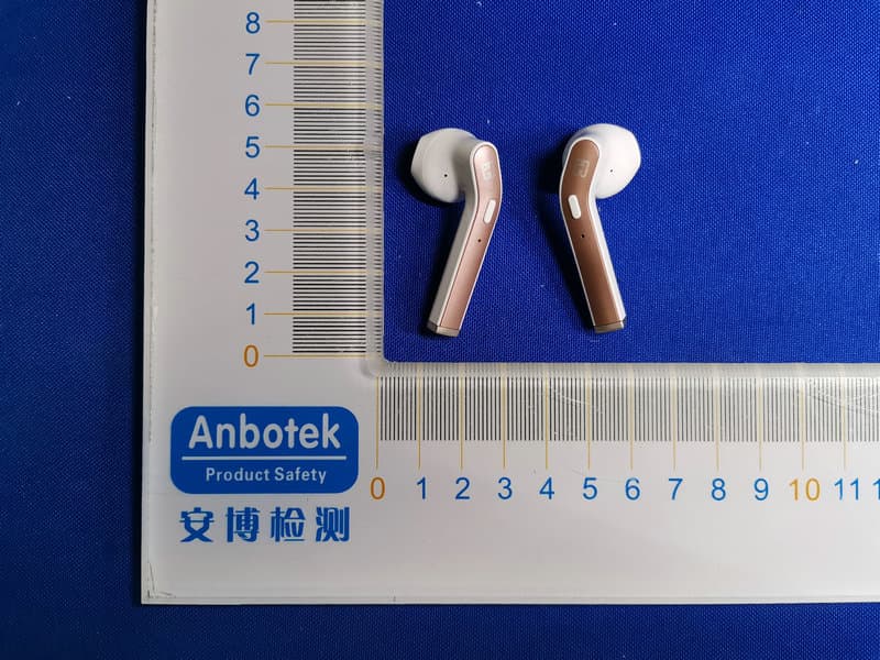
Click to zoom
Application Details
- Equipment Class
- DSS - Part 15 Spread Spectrum Transmitter
- Date of Grant
- Jul 07, 2020
- Application Purpose
- Original Equipment
- Date of Application
- Jul 07, 2020
- Equipment Note
- TWS Stick Earbuds
- Frequency Range
- 2402.00000000 - 2480.00000000
- Company
- Bytech NY Inc.
- Country
- United States
Documents & Files
Document Text
Text extracted from the exhibit documents filed with the FCC. Open a document above to read the original.
Users Manual
cover pages 1 & 2 pages 3 & 4 口au d i o I Bluetooth "' TRUE WIRELESS EARBUDS Package Contents: • True Wireless Earbuds • Charging Travel Case • Micro USB Charging Cable • Instruction Manual Specifications: Bluetoot甲Version:5.0 Working distance: 33 ft Charge Connector: Micro USB Frequency Response: 20Hz-20KHz Sensitivity: 95 db/ 1 khz Charging voltage: 5V/1A Charge time: 1-2 hrs Play Time: 2-3 hrs Operation Guide Microphone Control Button Indicator LED Indicator LEDs Micro USB Charging Port Getting Started Before using this device, fully charge it. Charging instructions can be found on pa ge 6. Open the charging case and take out the earbuds. Both LED lights will flash red and blue until one of the earbuds flashes red and blue, while the other earbud flashes blue, indicating that the right and left earbuds have synced to each other. Pairing 1. Go to Bluetooth ® Settings on your mobile device. 2. Turn Bluetoot阳ON, on your device. 3. On your Bluetooth ® device, select "iH AUBE301" from the list of available devices. 4. The earbud indicator LEDs will shut off to indicate they are connected. Basic Functions Right Earbud: , Double press the control button to play or pause the audio. • Press and hold to skip to the next audio track. • Single press to raise the volume. Left Earbud: • Press and hold to skip to the previous audio track. • Single press to lower the volume. Phone calls When there is an incoming call, the unit will pause the playback and ring to alert you of the call. Phone call functions work the same on either of the earbuds.* To answer an incoming call, single press the control button of either earbud. To end a call, double press the control button. To reject an incoming call, press and hold the control button. *Volume controls may not work during phone calls with some smartphone models. pages 5 & 6 pages 7 & 8 back 曰 QfJ 中 Troubleshootings Earbuds do not sync with each other: 1. Place the earbuds in the case, then take out the earbuds, ensuring both earbuds are turned on. 2. On each earbud, press and hold the control button for 5 seconds. The earbud will turn off after the LED flashes purple 3 times. 3. Replace the earbuds in the charging case. 4. Repeat the Getting Started process. Earbuds do not pair to device: 1. Turn the Earbuds OFF by pressing the control button on each earbud until the LED blinks red, and then turns off. 2. Replace the earbuds in the case. Turn your device's Bluetooth ® OFF and then back ON. Then repeat the pairing process. Charging 1. Replace the earbuds in the case. 2. Connect the Micro USB charging cable to the charging port on the bottom of the case. 3. Plug the cable into a standard USB 5V/1A or higher power output. When you plug the case into a charging mechanism the bottom light on the front of the case glows red. This means the case battery is being charged. The white lights indicate available case battery charge. While this is happening the lights on the buds inside the case glow solid red, which indicates they are being charged. When fully charged the case LEDs will glow solid and the earbud LEDs will shut off. 4. When fully charged, unplug the charging cable from the power source. If want to charge the earbuds from the charge case internal battery, simply replace them in the case. The case LEDs will show battery status and red charging, the LEDs on the buds will glow solid red. Warnings • Do not use this unit for anything other than its intended use. • Do not puncture, throw, drop, bend, or modify this product. • Do not throw this product into fire or water. • Do not short-curcuit the battery with any metal or metallic objects. • Do not expose this product to corrosive liquids such as salt water. • Do not operate the unit if it has been wet or moist to prevent against electric shock and/or injury to yourself and damage to the unit. • Do not allow children to play with this product as it is not a toy, and may present a choking hazard • Avoid leaving your device in direct sunlight, such as on the dashboard, console, or seat of a vehicle. • Do not leave your device, or use your device, in any area where the temperature is likely to drop below 32 ° F, or may exceed 140 ° F, such as inside a closed vehicle on a hot day. • Repairs to electrical equipment should only be performed by a qualified electrician. Improper repairs may place the user at serious risk. • Protect your hearing by always listening at a safe level. Prolonged use at elevated volumes may affect your hearing capacity and could result in hearing loss. • Use the earbuds with this charging case only. • To avoid damage to the charging case, please only use a USB 5V/1A or higher charger. • In order to ensure the battery life, charge normally at least once a month. FCC FCC ID: 2AHN6-IHBE301 Warranty Bytech NY INC. warrants this product to be materially free from defects and workmanship to the original purchaser for a period of 12 months from the original purchase date. Bytech responsibility with regard to this limited warranty shall be limited solely to repair or replacement at its option, of any product which fails during normal consumer use. This warranty does not extend to damage or failure which results from misuse, neglect, accident, alteration, abuse, improper installation or maintenance. At any time during the 12 months period following the purchase, the product fails due to defects in material or workmanship, return the defective product (with freight prepaid) with proof of purchase. WWW.BYTECHINTL.COM Bytech NY Inc 2585 West 13street Brooklyn NY 11223 (718) 449-3700 CE @J (j e). MADE IN CHINA ©2020 BYTECH NY INC. *All trademarks and copyrights are the property of the respective companies. 旧-AU-BE-301-WTUser Manual vl.1 060220 Black ink only, thin glossy paper, staple saddle bound, 5 sheets front & back Model:IH-AU-BE-301 FCC STATEMENT : This device complies with Part 15 of the FCC Rules. Operation is subject to the following two conditions: (1) This device may not cause harmful inter…
Text truncated - open the document above for the full version.
External Photos
FCC ID: 2AHN6-IHBE301
ID Label/Location Info
Label Location On EUT LeftRight Label FCC ID: 2AHN6-IHBE301
Internal Photos
FCC ID: 2AHN6-IHBE301 ANT
Operational Description
version01 Bytech NY Inc. Declaration concerning Antenna Specification It is hereby declared that the product Model No.: IH-AU-BE-301 FCCID:2AHN6-IHBE301 fulfills the requirement in FCC test relating to the antenna type. The device specified above confirms to the FCC recommendations for internal antenna type(s) described below: Model No. of antenna: IH-AU-BE-301 Type of antenna: Ceramic Antenna Gain of the antenna: -0.58 dBi Frequency range: 2402-2480MHz The mounting of the antenna is fixed to the radio module and no other antenna should be used. Company name: Bytech NY Inc. Address: 2585 West 13th Street,Brooklyn NY 11223, United States City:New York ZIP / Postal code: N/A Country:United States Place:United StatesDate: 2020-07-07 Signature:
RF Exposure Info
RF EXPOSURE EVALUATION FCC ID: 2AHN6-IHBE301 According to FCC 1.1310: The criteria listed in the following table shall be used to evaluate the environment impact of human exposure to radio frequency(RF) Radiation as specified in §1.1307(b): Routine SAR evaluation refers to that specifically required by §2.1093, using measurements or computer simulation. When routine SAR evaluation is not required, portable transmitters withoutput power greater than the applicable low threshold require SAR evaluation to qualify for TCB approval. Channel (MHz) Maximum output power (dBm) Tune up tolerance (dBm) Max Tune Up Power (dBm) Distance (mm) Calculation results Limit Operating Mode 2402-3.381 -3.381±1 -2.38150.1793 BDR+EDR 2441-3.340 -3.340±1-2.34050.1823 2480-1.172 -1.172±1 -0.17250.3033 2402-3.263 -3.263±1 -2.26350.1843 2441-3.212 -3.212±1-2.21250.1883 2480-1.298 -1.298±1 -0.29850.2943 Test Results:PASS.
Test Report
Report No.: 18220WC00076501FCC ID: 2AHN6-IHBE301Page 1 of 68 Code:AB-RF-05-a FCC TEST REPORT Client Name: Bytech NY Inc. Address: 2585 West 13th Street,Brooklyn NY 11223, United States Product Name: TWS Stick Earbuds Date: Jul. 06, 2020 Shenzhen Anbotek Compliance Laboratory Limited Report No.: 18220WC00076501FCC ID: 2AHN6-IHBE301Page 2 of 68 Code:AB-RF-05-a Contents 1. General Information ............................................................................................................................................... 5 1.1. Client Information ....................................................................................................................................... 5 1.2. Description of Device (EUT) ..................................................................................................................... 5 1.3. Auxiliary Equipment Used During Test ................................................................................................... 6 1.4. Description of Test Modes ........................................................................................................................ 6 1.5. List of channels ........................................................................................................................................... 7 1.6. Description Of Test Setup ......................................................................................................................... 8 1.7. Test Equipment List .................................................................................................................................... 9 1.8. Measurement Uncertainty ....................................................................................................................... 10 1.9. Description of Test Facility ...................................................................................................................... 10 2. Summary of Test Results ................................................................................................................................... 11 3. Conducted Emission Test ................................................................................................................................... 12 3.1. Test Standard and Limit .......................................................................................................................... 12 3.2. Test Setup .................................................................................................................................................. 12 3.3. Test Procedure .......................................................................................................................................... 12 3.4. Test Data .................................................................................................................................................... 12 4. Radiation Spurious Emission and Band Edge ................................................................................................ 17 4.1. Test Standard and Limit .......................................................................................................................... 17 4.2. Test Setup .................................................................................................................................................. 17 4.3. Test Procedure .......................................................................................................................................... 18 4.4. Test Data .................................................................................................................................................... 19 5. Maximum Peak Output Power Test .................................................................................................................. 27 5.1. Test Standard and Limit .......................................................................................................................... 27 5.2. Test Setup .................................................................................................................................................. 27 5.3. Test Procedure .......................................................................................................................................... 27 5.4. Test Data .................................................................................................................................................... 27 6. 20DB Occupy Bandwidth Test ........................................................................................................................... 31 6.1. Test Standard ............................................................................................................................................ 31 6.2. Test Setup .................................................................................................................................................. 31 6.3. Test Procedure .......................................................................................................................................... 31 6.4. Test Data .................................................................................................................................................... 31 7. Carrier Frequency Separation Test ................................................................................................................... 35 7.1. Test Standard and Limit .......................................................................................................................... 35 7.2. Test Setup .................................................................................................................................................. 35 7.3. Test Procedure .......................................................................................................................................... 35 7.4. Test Data .....................…
Text truncated - open the document above for the full version.
Test Setup Photos
FCC ID: 2AHN6-IHBE301 Photo of Conducted Emission Measurement Photo of Radiation Emission Test
Contact Information
Applicant
Soli Mizrahi
Test Firm
Shenzhen Anbotek Compliance Laboratory LimitedJeff Zhu
Technical Specifications
| # | Rule Parts | Frequency Range | Power Output |
|---|---|---|---|
| 1 | 15C | 2.40 GHz - 2.48 GHz | 800.00 µW |
Other Applications from Bytech NY Inc.
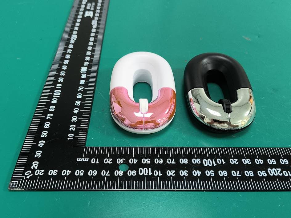
2AHN6-MSWS139
Aug 13, 2026Wireless Mouse
Equipment Class
DXX - Part 15 Low Power Communication Device Transmitter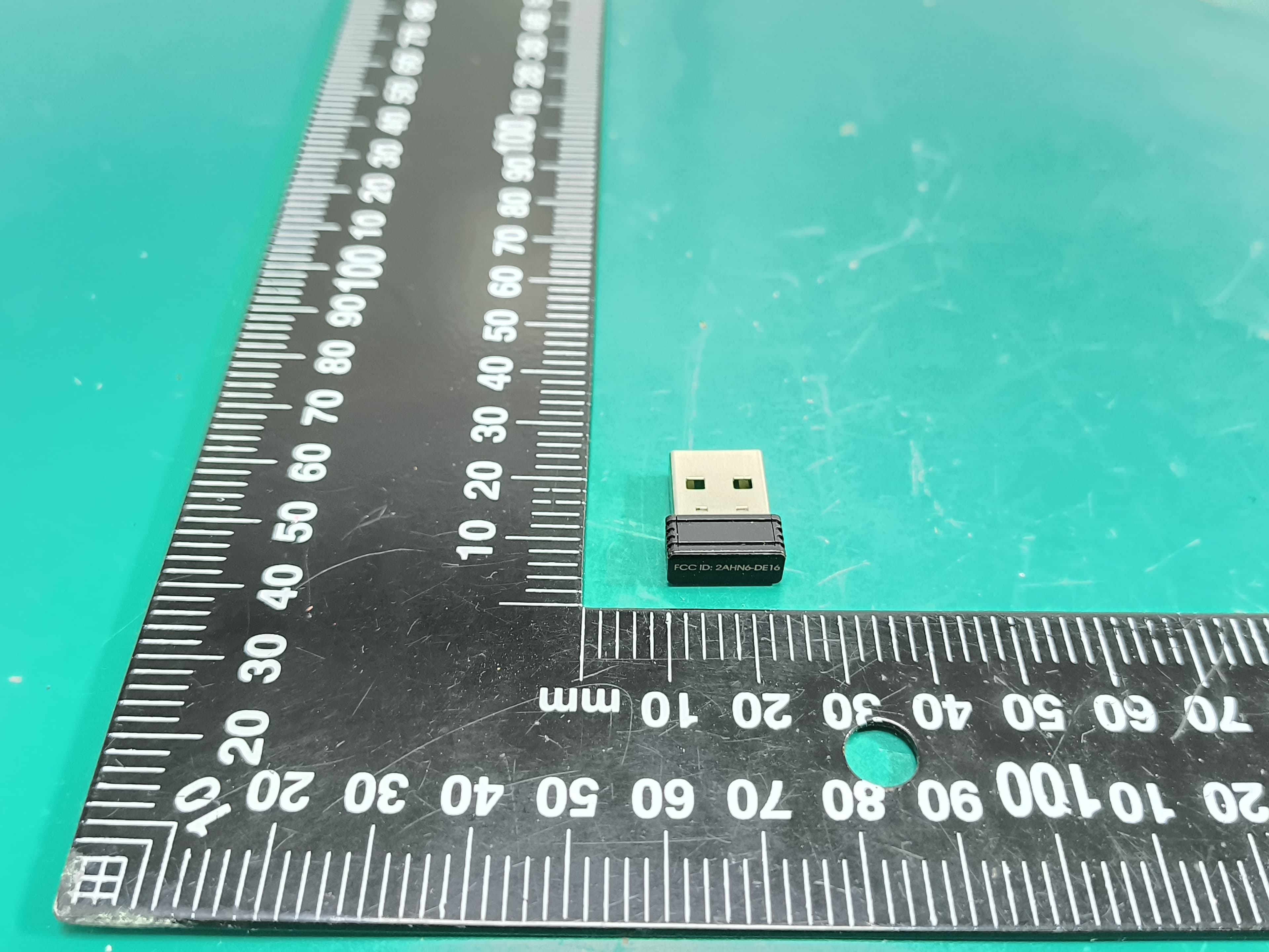
2AHN6-DE16
Aug 13, 2026Wireless mouse-dongle
Equipment Class
DXX - Part 15 Low Power Communication Device Transmitter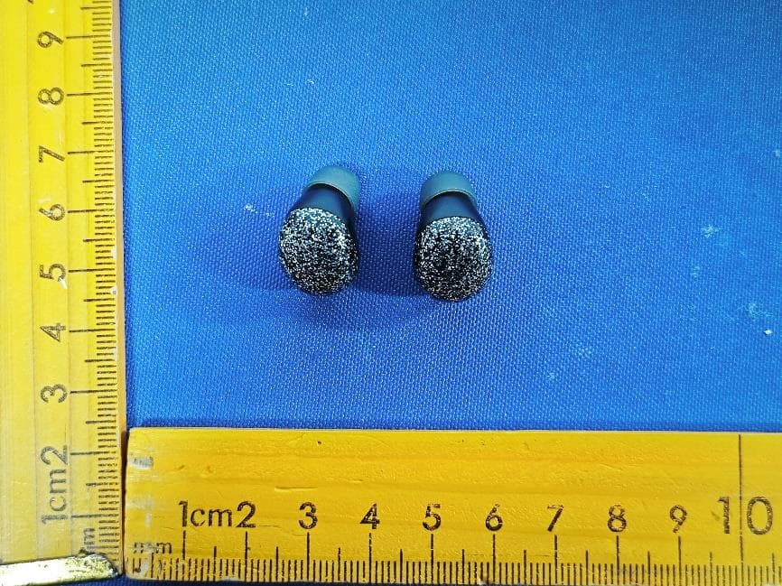
2AHN6-AUBE231
Jun 22, 2026Glitter TWS Earbuds-Asst
Equipment Class
DSS - Part 15 Spread Spectrum Transmitter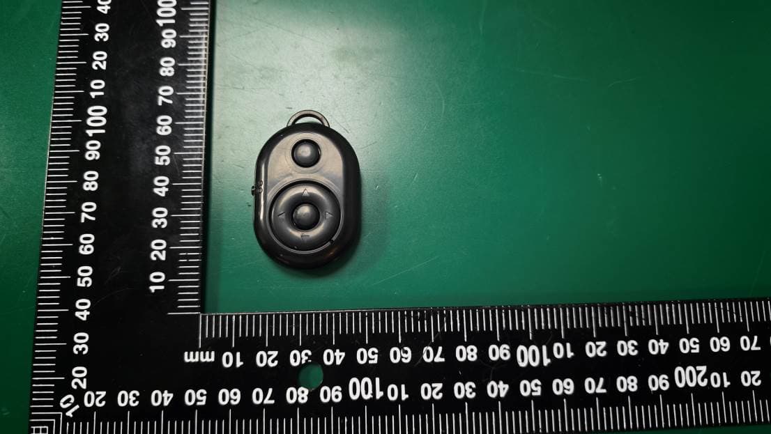
2AHN6-SFSH102
May 26, 2026Blth Remote Selfie Shutter-BK
Equipment Class
DTS - Digital Transmission System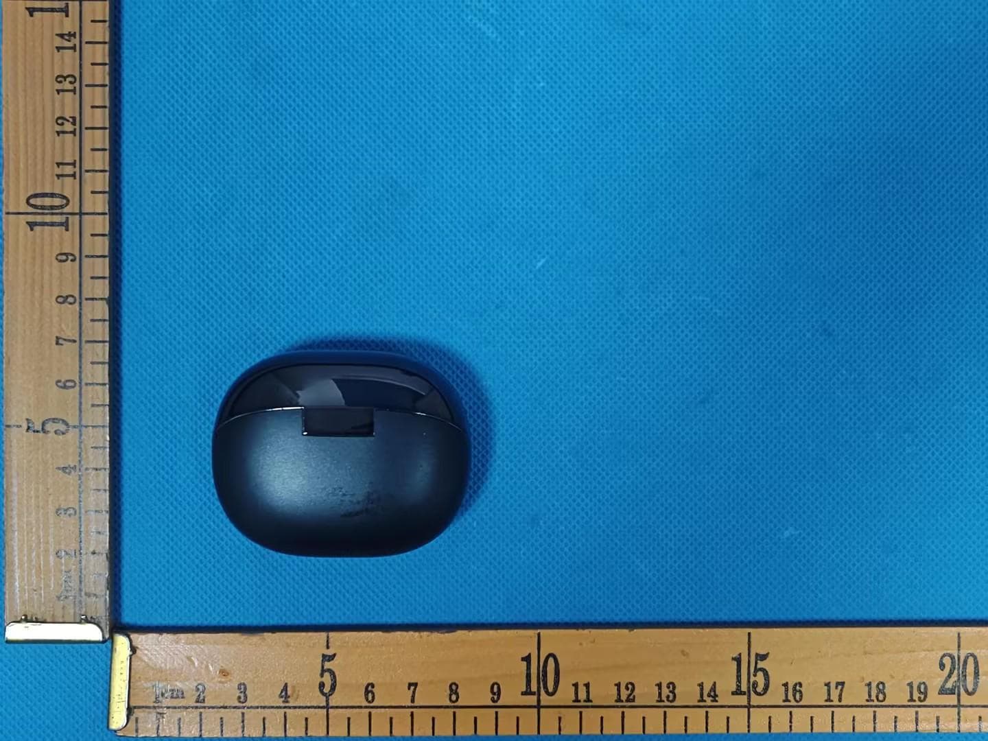
2AHN6-BCBE147
May 06, 2026WIRELESS EARBUDS
Equipment Class
DSS - Part 15 Spread Spectrum Transmitter