2AHPN-BE2848Automotive Infotainment Unit with Bluetooth/WLAN
Harman International Industries, Inc.
Click to zoom
Application Details
- Equipment Class
- DSS - Part 15 Spread Spectrum Transmitter
- Date of Grant
- Apr 06, 2020
- Application Purpose
- Original Equipment
- Date of Application
- Apr 06, 2020
- Equipment Note
- Automotive Infotainment Unit with Bluetooth/WLAN
- Frequency Range
- 2402.00000000 - 2480.00000000
- Country
- United States
Documents & Files
Document Text
Text extracted from the exhibit documents filed with the FCC. Open a document above to read the original.
Users Manual
2020 PACIFICA AND VOYAGER ©2019 FCA US LLC. All Rights Reserved. Chrysler is a registered trademark of FCA US LLC or FCA Canada Inc., used under license. App Store is a registered trademark of Apple Inc. Google Play Store is a registered trademark of Google. 20_RU_OM_EN_US_N Second Edition Pacifica and Voyager OWNER’S MANUAL 2020 owners.mopar.ca DOWNLOAD A FREE ELECTRONIC COPY OF THE MOST UP-TO-DATE OWNER’S MANUAL, UCONNECT AND WARRANTY BOOKLETS U. S. Canada mopar.com/om Whether it’s providing information about specific product features, taking a tour through your vehicle’s heritage, knowing what steps to take following an accident or scheduling your next appointment, we know you’ll find the app an important extension of your Chrysler brand vehicle. Simply download the app, select your make and model and enjoy the ride. To get this app, go directly to the App Store® or Google Play® Store and enter the search keyword “Chrysler” (U.S. residents only). WARNING: Operating, servicing and maintaining a passenger vehicle or off-highway motor vehicle can expose you to chemicals including engine exhaust, carbon monoxide, phthalates, and lead, which are known to the State of California to cause cancer and birth defects or other reproductive harm. To minimize exposure, avoid breathing exhaust, do not idle the engine except as necessary, service your vehicle in a well-ventilated area and wear gloves or wash your hands frequently when servicing your vehicle. For more information go to www.P65Warnings.ca.gov/passenger-vehicle. This Owner’s Manual illustrates and describes the operation of features and equipment that are either standard or optional on this vehicle. This manual may also include a description of features and equipment that are no longer available or were not ordered on this vehicle. Please disregard any features and equipment described in this manual that are not on this vehicle. FCA US LLC reserves the right to make changes in design and specifications, and/or make additions to or improvements to its products without imposing any obligation upon itself to install them on products previously manufactured. With respect to any vehicles sold in Canada, the name FCA US LLC shall be deemed to be deleted and the name FCA Canada Inc. used in substitution therefore. If you are the first registered retail owner of your vehicle, you may obtain a complimentary printed copy of the Warranty Booklet by calling 1-800-247-9753 (U.S.) or 1-800-387-1143 (Canada) or by contacting your dealer. This Owner’s Manual is intended to familiarize you with the important features of your vehicle. Your most up-to-date Owner’s Manual, Navigation/ Uconnect manuals and Warranty Booklet can be found by visiting the website on the back cover. U.S. residents can purchase replacement kits by visiting www.techauthority.com and Canadian residents can purchase replacement kits by calling 1-800-387-1143. The driver’s primary responsibility is the safe operation of the vehicle. Driving while distracted can result in loss of vehicle control, resulting in an accident and personal injury. FCA US LLC strongly recommends that the driver use extreme caution when using any device or feature that may take their attention off the road. Use of any electrical devices, such as cellular telephones, computers, portable radios, vehicle navigation or other devices, by the driver while the vehicle is moving is dangerous and could lead to a serious accident. Texting while driving is also dangerous and should never be done while the vehicle is moving. If you find yourself unable to devote your full attention to vehicle operation, pull off the road to a safe location and stop your vehicle. Some states or provinces prohibit the use of cellular telephones or texting while driving. It is always the driver’s responsibility to comply with all local laws. This Owner’s Manual has been prepared to help you get acquainted with your new Chrysler brand vehicle and to provide a convenient reference source for common questions. Not all features shown in this manual may apply to your vehicle. For additional information, visit www.mopar.com (U.S.), www.mopar.ca (Canada) or your local Chrysler brand dealer. Drunk driving is one of the most frequent causes of accidents. Your driving ability can be seriously impaired with blood alcohol levels far below the legal minimum. If you are drinking, don’t drive. Ride with a designated non-drinking driver, call a cab, a friend or use public transportation. DRIVING AND AL COHOL Driving after drinking can lead to an accident. Your perceptions are less sharp, your reflexes are slower and your judgment is impaired when you have been drinking. Never drink and then drive. WARNING! WARNING: Operating, servicing and maintaining a passenger vehicle or off-highway motor vehicle can expose you to chemicals including engine exhaust, carbon monoxide, phthalates, and lead, which are known to the State of California to cause cancer and birth defects or other reproductive harm. To minimize exposure, avoid breathing exhaust, do not idle the engine except as necessary, service your vehicle in a well-ventilated area and wear gloves or wash your hands frequently when servicing your vehicle. For more information go to www.P65Warnings.ca.gov/passenger-vehicle. This Owner’s Manual illustrates and describes the operation of features and equipment that are either standard or optional on this vehicle. This manual may also include a description of features and equipment that are no longer available or were not ordered on this vehicle. Please disregard any features and equipment described in this manual that are not on this vehicle. FCA US LLC reserves the right to make changes in design and specifications, and/or make additions to or improvements to its products without imposing any obligation upon itself to install them on products previously manufactured. With respect to any vehicles sold in Canada, the name FCA US LLC shall be deemed to be deleted …
Text truncated - open the document above for the full version.
Users Manual
GETTING TO KNOW YOUR VEHICLE91 Climate Control Functions Air Conditioning (A/C) The Air Conditioning (A/C) button allows the operator to manually activate or deactivate the air conditioning system. When in A/C mode with the ATC set to a cool temperature, dehumidified air flows through the air outlets. If Economy mode is desired, push the A/C button to turn off the A/C mode in the Automatic Temperature Control (ATC) display and deactivate the A/C system. NOTE: If the system is in Mix or Defrost Mode, the A/C can be turned off, but the A/C system shall remain active to prevent fogging of the windows. If not operating in AUTO mode, the system will not automatically sense the presence of fog, mist or ice on the windshield. Defrost Mode must be manually selected to clear the windshield and side glass. If fog or mist appears on the windshield or side glass, select Defrost Mode and adjust blower speed if needed. Recirculation For Automatic Temperature Control When outside air contains smoke, odors, or high humidity, or if rapid cooling is desired, you may wish to recirculate interior air by pressing the Recirculation control button. The recircula- tion indicator will illuminate when this button is selected. Press the button a second time to turn off the Recirculation mode and allow outside air into the vehicle. NOTE: In cold weather, use of recirculation mode may lead to excessive window fogging. The recirculation feature may be unavailable (button on the touch- screen greyed out) if conditions exist that could create fogging on the inside of the windshield. On systems with Manual Climate Controls, the Recir- culation mode is not allowed in Defrost Mode to improve window clearing operation. Recirculation will be disabled automatically if this mode is selected. Attempting to use Recirculation while in this mode will cause the LED in the control button to blink and then turn off. AUTO Button Automatically controls the interior cabin temperature by adjusting airflow distribution and amount. Performing this function will cause the system to switch between manual mode and automatic modes. Refer to “Automatic Operation” within this section for more information. Rear Climate Control/Blower Off To manually set the rear blower controls to off, press the Rear Climate Control/Blower Off button. IconDescription 2 20_RU_OM_EN_USC_t.book Page 91 92 GETTING TO KNOW YOUR VEHICLE Automatic Temperature Control (ATC) — If Equipped Automatic Operation 1. Push the AUTO button on the faceplate, or the AUTO button on the touchscreen on the Automatic Temperature Control (ATC) Panel. 2. Next, adjust the temperature you would like the system to maintain by adjusting the driver and passenger temperature control buttons. Once the desired temperature is displayed, the system will achieve and auto- matically maintain that comfort level. 3. When the system is set up for your comfort level, it is not necessary to change the settings. You will experience the greatest efficiency by simply allowing the system to function automatically. NOTE: It is not necessary to move the temperature settings for cold or hot vehicles. The system automatically adjusts the temperature, mode, and blower speed to provide comfort as quickly as possible. The temperature can be displayed in U.S. or Metric units by selecting the U.S./Metric customer-programmable feature. Refer to the “Uconnect Settings” in “Multimedia” for further information. To provide you with maximum comfort in the Automatic mode during cold start-ups, the blower fan will remain on low until the engine warms up. The blower will increase in speed and transition into Auto mode. Manual Operation Override This system offers a full complement of manual override features. The AUTO symbol in the front Automatic Temperature Control (ATC) display will be turned off when the system is being used in the manual mode. Operating Tips NOTE: Refer to the chart at the end of this section for suggested control settings for various weather conditions. Summer Operation The engine cooling system must be protected with a high-quality antifreeze coolant to provide proper corrosion protection and to protect against engine overheating. OAT coolant (conforming to MS.90032) is recommended. Refer to “Fluids And Lubricants” in “Technical Specifications” for proper coolant selection. Winter Operation To ensure the best possible heater and defroster performance, make sure the engine cooling system is functioning properly and the proper amount, type, and concentration of coolant is used. Refer to “Fluids And Lubri- cants” in “Technical Specifications” for proper coolant selection. Use of the air Recirculation mode during Winter months is not recom- mended, because it may cause window fogging. Vacation/Storage Before you store your vehicle, or keep it out of service (i.e., vacation) for two weeks or more, run the air conditioning system at idle for about five minutes, in fresh air with the blower setting on high. This will ensure adequate system lubri- cation to minimize the possibility of compressor damage when the system is started again. 20_RU_OM_EN_USC_t.book Page 92 GETTING TO KNOW YOUR VEHICLE93 Window Fogging Vehicle windows tend to fog on the inside in mild, rainy, and/or humid weather. To clear the windows, select Defrost or Mix mode and increase the front blower speed. Do not use the Recirculation mode without A/C (air condi- tioning) for long periods, as fogging may occur. Outside Air Intake Make sure the air intake, located directly in front of the windshield, is free of obstructions such as leaves. Leaves collected in the air intake may reduce airflow, and if they enter the plenum, they could plug the water drains. In Winter months, make sure the air intake is clear of ice, slush, and snow. A/C Air Filter The Climate Control system filters out dust and pollen from the air. Refer to an authorized dealer for filter replacement instructions. Operating Tips Chart CAUTION! Failure to follow these caut…
Text truncated - open the document above for the full version.
Users Manual
SAFETY201 Lower Anchors And Tethers For CHildren (LATCH) Restraint System LATCH Label Your vehicle is equipped with the child restraint anchorage system called LATCH, which stands for Lower Anchors and Tethers for CHildren. The LATCH system has three vehicle anchor points for installing LATCH-equipped child seats. There are two lower anchorages located at the back of the seat cushion where it meets the seatback and one top tether anchorage located behind the seating position. These anchorages are used to install LATCH-equipped child seats without using the vehicle’s seat belts. Some seating positions may have a top tether anchorage but no lower anchorages. In these seating positions, the seat belt must be used with the top tether anchorage to install the child restraint. Please see the following table for more information. LATCH Positions For Installing Child Restraints In This Vehicle If applicable, refer to the “Hybrid Supplement” for additional information. 7 Passenger Bench Seat LATCH Positions 7 Passenger Stow ‘n Go Seating LATCH Positions 8 Passenger LATCH Positions Lower Anchorage Symbol 2 anchorages per seating position Top Tether Anchorage Symbol Lower Anchorage Symbol 2 anchorages per seating position Top Tether Anchorage Symbol Lower Anchorage Symbol 2 anchorages per seating position Top Tether Anchorage Symbol 4 20_RU_OM_EN_USC_t.book Page 201 202SAFETY Frequently Asked Questions About Installing Child Restraints With LATCH What is the weight limit (child’s weight + weight of the child restraint) for using the LATCH anchorage system to attach the child restraint? 65 lbs (29.5 kg)Use the LATCH anchorage system until the combined weight of the child and the child restraint is 65 lbs (29.5 kg). Use the seat belt and tether anchor instead of the LATCH system once the combined weight is more than 65 lbs (29.5 kg). Can the LATCH anchorages and the seat belt be used together to attach a rear-facing or forward-facing child restraint? NoDo not use the seat belt when you use the LATCH anchorage system to attach a rear-facing or forward-facing child restraint. Booster seats may be attached to the LATCH anchorages if allowed by the booster seat manufacturer. See your booster seat owner’s manual for more information. Can two child restraints be attached using a common lower LATCH anchorage? NoNever “share” a LATCH anchorage with two or more child restraints. If the center position does not have dedicated LATCH lower anchorages, use the seat belt to install a child seat in the center position next to a child seat using the LATCH anchorages in an outboard position. Can the rear-facing child restraint touch the back of the front passenger seat? YesThe child seat may touch the back of the front passenger seat if the child restraint manufacturer also allows contact. See your child restraint owner’s manual for more information. 20_RU_OM_EN_USC_t.book Page 202 SAFETY203 NOTE: If the folding, non-adjustable head restraint interferes with the installation of the child restraint, the head restraint may be folded and the child seat installed in front of it. Car Seat With Head Restraint Folded Can the rear head restraints be removed?YesThe 2nd row head restraints on bench and the center head restraint in the 8 passenger vehicle can be removed if they interfere with the installation of the child restraint. 2nd row Stow 'n Go head restraints are not removable. The 3rd row center head restraint is removable in all vehicles, but the 3rd row outboard head restraints are not removable. Refer to “Head Restraints” in “Getting To Know Your Vehicle” for further information. Frequently Asked Questions About Installing Child Restraints With LATCH WARNING! Always make sure the head restraint is in its upright position when the seat is to be used by an occupant who is not in a child restraint. Sitting in a seat with the head restraint in its lowered position could result in serious injury or death in a collision. 1 — Folded Headrest 2 — Child Restraint 4 20_RU_OM_EN_USC_t.book Page 203 204SAFETY Locating The LATCH Anchorages If applicable, refer to the “Hybrid Supplement” for additional information. The lower anchorages are round bars that are found at the rear of the seat cushion where it meets the seatback, below the anchorage symbols on the seatback. They are just visible when you lean into the rear seat to install the child restraint. You will easily feel them if you run your finger along the gap between the seatback and seat cushion. LATCH Anchorages (Second Row Anchorages Shown) 7 Passenger Stow ‘n Go Seating LATCH Anchorages (Second Row Anchorages Shown) 8 Passenger Seating LATCH Anchorages (Second Row Bench Anchorages Shown) 7 Passenger Bench Seating Locating The Upper Tether Anchorages If applicable, refer to the “Hybrid Supplement” for additional information. There are tether strap anchorages located behind all second row seating positions. The third row has a tether anchor on the 40% seat for the right outboard position and in the center of the 60% seat for either the center or left outboard seating position. All tether anchorages are located on the back of the seat, near the floor. Tether Strap Anchorages (Second Row 7 Passenger Stow ‘n Go Anchorage Shown) 20_RU_OM_EN_USC_t.book Page 204 SAFETY205 Tether Strap Anchorages (Second Row 8 Passenger Anchorage Shown) Tether Strap Anchorages (Third Row 60/40 Anchorage Shown) LATCH-compatible child restraint systems will be equipped with a rigid bar or a flexible strap on each side. Each will have a hook or connector to attach to the lower anchorage and a way to tighten the connection to the anchorage. Forward-facing child restraints and some rear-facing child restraints will also be equipped with a tether strap. The tether strap will have a hook at the end to attach to the top tether anchorage and a way to tighten the strap after it is attached to the anchorage. Center Seat LATCH This vehicle has 4 lower LATCH anchorages in the third row, rear seat. Anchorage…
Text truncated - open the document above for the full version.
Users Manual
STARTING AND OPERATING269 NOTE: It is the driver’s responsibility to use the brake and stop the vehicle. The driver should check their surroundings and be prepared to stop the vehicle either when instructed to, or when driver intervention is required. Once the vehicle is in a standstill condition, the driver will be instructed to place the gear selector into the REVERSE position. Check Surroundings — Shift To Reverse When the driver places the gear selector into the REVERSE position, the system may instruct the driver to wait for steering to complete. Check Surroundings — Wait For Steering To Complete The system will then instruct the driver to check their surroundings and move backward. Check Surroundings — Move Backward The vehicle is now in the parallel park position. When the maneuver is complete, the driver will be instructed to check the vehicle's parking position. If the driver is satisfied with the vehicle position, they should shift to PARK. The "Active ParkSense Complete - Check Parking Position" message will be momentarily displayed. Active ParkSense Complete — Check Parking Position 5 20_RU_OM_EN_USC_t.book Page 269 270STARTING AND OPERATING Perpendicular Parking Space Assistance Operation/Display When the ParkSense Active Park Assist system is enabled, the “Active ParkSense Searching - Push OK for Perpendicular Park” message will show in the instrument cluster display. Push the OK button on the left side steering wheel switch to change your parking space setting to a perpendicular maneuver. You may switch back to parallel parking if you desire. Once the driver pushes OK for a perpendicular parking maneuver, the “Active ParkSense Searching - Push OK for Parallel Park” message will appear in the instrument cluster display. Active ParkSense Searching Display NOTE: When searching for a parking space, use the turn signal indicator to select which side of the vehicle you want to perform the parking maneuver. The ParkSense Active Park Assist system will automatically search for a parking space on the passenger's side of the vehicle if the turn signal is not activated. The driver needs to make sure that the selected parking space for the maneuver remains free and clear of any obstructions (e.g. pedestrians, bicycles, etc.). The driver is responsible to ensure that the selected parking space is suitable for the maneuver and free/clear of anything that may be overhanging or protruding into the parking space (e.g., ladders, tailgates, etc. from surrounding objects/vehicles). When seeking for a parking space, the driver should drive as parallel or perpendicular (depending on the type of maneuver) to other vehicles as possible. The feature will only indicate the last detected parking space (example: if passing multiple available parking spaces, the system will only indicate the last detected parking space for the maneuver). 20_RU_OM_EN_USC_t.book Page 270 STARTING AND OPERATING271 When an available parking space has been found, and the vehicle is not in position, you will be instructed to move forward to position the vehicle for a perpendicular parking sequence. Parking Space Found — Keep Moving Forward Once the vehicle is in position, you will be instructed to stop the vehicle’s movement and remove your hands from the steering wheel. Parking Space Found — Stop And Remove Hands From Wheel Once the vehicle is at a standstill with your hands removed from the steering wheel, you will be instructed to place the gear selector into the REVERSE position. Parking Space Found — Shift To Reverse 5 20_RU_OM_EN_USC_t.book Page 271 272STARTING AND OPERATING When the driver places the gear selector into the REVERSE position, the system may instruct the driver to wait for steering to complete. Check Surroundings — Wait For Steering To Complete The system will then instruct the driver to check their surroundings and move backward. Check Surroundings — Move Backwards NOTE: It is the driver’s responsibility to use the brake and accelerator during the semi-auto- matic parking maneuver. When the system instructs the driver to remove their hands from the steering wheel, the driver should check their surroundings and begin to back up slowly. The ParkSense Active Park Assist system will allow a maximum of eight shifts between DRIVE or REVERSE. If the maneuver cannot be completed within eight shifts, the system will cancel and the instrument cluster display will instruct the driver to complete the maneuver manually. The system will cancel the maneuver if the vehicle speed exceeds 5 mph (7 km/h) during active steering guidance into the parking space. The system will provide a warning to the driver at 3 mph (5 km/h) that tells them to slow down. The driver is then responsible for completing the maneuver if the system is canceled. If the system is canceled during the maneuver for any reason, the driver must take control of the vehicle. When the vehicle has reached the end of its backward movement, the system will instruct the driver to check their surroundings and stop the vehicle’s movement. Check Surroundings — STOP NOTE: It is the driver’s responsibility to use the brake and stop the vehicle. The driver should check their surroundings and be prepared to stop the vehicle either when instructed to, or when driver intervention is required. 20_RU_OM_EN_USC_t.book Page 272 STARTING AND OPERATING273 Once the vehicle is in a standstill condition, the driver will be instructed to place the gear selector into the DRIVE position. Check Surroundings — Shift To Drive When the driver places the gear selector into the DRIVE position, the system may instruct the driver to wait for steering to complete. Check Surroundings — Wait For Steering To Complete The system will then instruct the driver to check their surroundings and move forward. Check Surroundings — Move Forward When the vehicle has reached the end of its forward movement, the system will instruct the driver to check their surroundings and stop the vehicle’…
Text truncated - open the document above for the full version.
Users Manual
IN CASE OF EMERGENCY325 Tire Service Kit Tire Service Kit And Components And Operation Tire Service Kit Components Using The Mode Select Knob And Hoses Your Tire Service Kit is equipped with the following symbols to indicate the air or sealant mode. Selecting Air Mode Push in the Mode Select Knob and turn to this position for air pump operation only. Selecting Sealant Mode Push in the Mode Select Knob and turn to this position to inject the Tire Service Kit Sealant and to inflate the tire. Using The Power Button Push and release the Power Button once to turn On the Tire Service Kit. Push and release the Power Button again to turn Off the Tire Service Kit. Using The Deflation Button Push the Deflation Button to reduce the air pressure in the tire if it becomes over-inflated. Tire Service Kit Usage Precautions Replace the Tire Service Kit Sealant Bottle prior to the expiration date (printed at the lower right hand corner on the bottle label) to assure optimum operation of the system. Refer to “Sealant Bottle Replacement” in this section for further information. The Sealant Bottle is a one tire application use and needs to be replaced after each use. Always replace these components immedi- ately at your original equipment vehicle dealer. When the Tire Service Kit sealant is in a liquid form, clean water, and a damp cloth will remove the material from the vehicle or tire and wheel components. Once the sealant dries, it can easily be peeled off and properly discarded. For optimum performance, make sure the valve stem on the wheel is free of debris before connecting the Tire Service Kit. 1 — Mode Select Knob 2 — Sealant/Air Hose 3 — Hose Accessories 4 — Sealant Bottle 5 — Power Plug 6 — Power Switch 7 — Deflation Button 8 — Pressure Gauge 6 20_RU_OM_EN_USC_t.book Page 325 326IN CASE OF EMERGENCY (Continued) (Continued) The Tire Service Kit Sealant is only intended to seal punctures less than 1/4 inch (6 mm) diameter in the tread/contact surface of your vehicle’s tires. The Tire Service Kit Sealant is not intended to seal punctures on the tires' side walls. You can use the Tire Service Kit air pump to inflate bicycle tires. The kit also comes with two needles, located in the Accessory Storage Compartment (on the bottom of the air pump) for inflating sport balls, rafts, or similar inflatable items. However, use only the Air Pump and make sure the Mode Select Knob is in the Air Mode when inflating such items to avoid injecting sealant into them. Do not lift or carry the Tire Service Kit by the hoses. WARNING! Do not attempt to seal a tire on the side of the vehicle closest to traffic. Pull far enough off the road to avoid the danger of being hit when using the Tire Service Kit. Do not use Tire Service Kit or drive the vehicle under the following circumstances: If the puncture in the tire tread is approximately 1/4 inch (6 mm) or larger. If the tire has any sidewall damage. If the tire has any damage from driving with extremely low tire pressure. If the tire has any damage from driving on a flat tire. If the wheel has any damage. If you are unsure of the condition of the tire or the wheel. Keep Tire Service Kit away from open flames or heat source. A loose Tire Service Kit thrown forward in a collision or hard stop could endanger the occupants of the vehicle. Always stow the Tire Service Kit in the place provided. Failure to follow these warnings can result in injuries that are serious or fatal to you, your passengers, and others around you. WARNING! (Continued) Take care not to allow the contents of Tire Service Kit to come in contact with hair, eyes, or clothing. Tire Service Kit sealant is harmful if inhaled, swallowed, or absorbed through the skin. It causes skin, eye, and respiratory irritation. Flush immediately with plenty of water if there is any contact with eyes or skin. Change clothing as soon as possible, if there is any contact with clothing. Tire Service Kit Sealant solution contains latex. In case of an allergic reaction or rash, consult a physician immediately. Keep Tire Service Kit out of reach of children. If swal- lowed, rinse mouth immediately with plenty of water and drink plenty of water. Do not induce vomiting! Consult a physician imme- diately. WARNING! (Continued) 20_RU_OM_EN_USC_t.book Page 326 IN CASE OF EMERGENCY327 Sealing A Tire With Tire Service Kit Whenever You Stop To Use Tire Service Kit: 1. Pull over to a safe location and turn on the vehicle’s Hazard Warning flashers. 2. Verify that the valve stem (on the wheel with the deflated tire) is in a position that is near to the ground. This will allow the Tire Service Kit Hose to reach the valve stem and keep the Tire Service Kit flat on the ground. This will provide the best positioning of the kit when injecting the sealant into the deflated tire and running the air pump. Move the vehicle as necessary to place the valve stem in this position before proceeding. 3. Place the transmission in PARK (P) and cycle the ignition in the OFF position. 4. Apply the parking brake. Setting Up To Use Tire Service Kit: 1. Uncoil the Sealant Hose and then remove the cap from the fitting at the end of the hose. 2. Place the Tire Service Kit flat on the ground next to the deflated tire. 3. Remove the cap from the valve stem and then screw the fitting at the end of the Sealant Hose onto the valve stem. 4. Uncoil the Power Plug and insert the plug into the vehicle’s 12 Volt power outlet. NOTE: Do not remove foreign objects (e.g., screws or nails) from the tire. Injecting Tire Service Kit Sealant Into The Deflated Tire: 1. Always start the vehicle before turning the Tire Service Kit on. 2. Ensure the Mode Select Knob is to the Sealant Mode position. 3. After pushing the Power Button, the sealant (white fluid) will flow from the Sealant Bottle through the Sealant Hose and into the tire. NOTE: Sealant may leak out through the puncture in the tire. 6 20_RU_OM_EN_USC_t.book Page 327 328IN CASE OF EMERGENCY If the sealan…
Text truncated - open the document above for the full version.
Contact Information
Applicant
Pranav Patel
Test Firm
Bureau Veritas Consumer Products Services, Inc.Sarb Shelopal
[email protected]+1 925 963 4420
Technical Specifications
| # | Rule Parts | Frequency Range | Power Output |
|---|---|---|---|
| 1 | 15C | 2.40 GHz - 2.48 GHz | 3.80 mW |
Other Applications from Harman International Industries, Inc.
2AHPN-BE2888
Aug 28, 2026Android-based infotainment head unit
Equipment Class
NII - Unlicensed National Information Infrastructure TX2AHPN-BE2885
Jan 07, 2026Infotainment head unit android based
Equipment Class
DSS - Part 15 Spread Spectrum Transmitter2AHPN-BE2886
Dec 02, 2025Automotive Front Passenger Display Module (FPDM)
Equipment Class
DSS - Part 15 Spread Spectrum Transmitter2AHPN-BE2874
Jul 30, 2024Infotainment head unit android based
Equipment Class
DSS - Part 15 Spread Spectrum Transmitter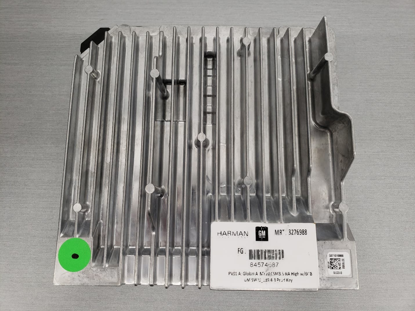
2AHPN-BE2866
Jul 27, 2023Automotive Infotainment Unit with Bluetooth/WLAN
Equipment Class
DTS - Digital Transmission System