2AHUUIMTTS2i-MTTS System Controller
Laser-Ammo Ltd.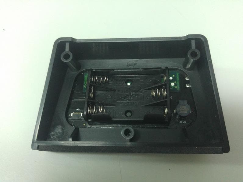
Click to zoom
Application Details
- Equipment Class
- DXT - Part 15 Low Power Transceiver, Rx Verified
- Date of Grant
- May 03, 2020
- Application Purpose
- Original Equipment
- Date of Application
- Apr 27, 2020
- Equipment Note
- i-MTTS System Controller
- Frequency Range
- 2410.00000000 - 2473.00000000
- Company
- Laser-Ammo Ltd.
- Country
- Israel
Documents & Files
Document Text
Text extracted from the exhibit documents filed with the FCC. Open a document above to read the original.
Users Manual
SYSTEM CONTROLLER for Interactive Multi Target Training System (i-M.T.T.S.) User Guide Introduction: The System Controller is a control and display unit for the already impressive I-MTTS targeting system for firearms training with Laser Ammo SureStrike products, acting both as a remote control and a numeric display for the user’s performance. Paired together to create the I-MTTS ARENA Training drill programs including: ➢ First shot timer ➢ Steel plate shooting ➢ ‘Chase the Ball’ ➢ Shoot – No shoot ➢ ‘Double tap’ ➢ Mag change timer The System Controller I-MTTS ARENA features include: • Wireless communication up to 20ft. • Immediate score display, hundreds of a second accuracy. • ‘Split’ and ‘Elapse’ times display. • Remote push-button change & selection. • Choice of Automatic or manual drill ‘Restart’. • Choice of Countdown or Random drill ‘Start’. • Control sound and light response. • Set of 4 changeable target cards for each target. • Usable as standalone targets. • Activated by both visible and non-visible lasers. • Scrolling through all the scores. • Change and set drill parameters. • Extended range. • Pair and define multiple target groups. And more The I-MTTS ARENA is designed to practicing home defense, IPSC, tactical, or even combat training for law enforcement, while developing target recognition, speed, firing accuracy and ‘shoot/no- shoot’ skills. The I-MTTS ARENA offers to you options that are not available in any other electronic target training system. Safety precautions: 1. This product is suited for three 1.5V-AAA batteries. Do not use any other battery type. 2. This product is powered by three consumer grade alkaline non-rechargeable batteries. 3. Do not mix rechargeable and non-chargeable batteries. The device should be loaded with three batteries of the same type. 2 Please Note: I-MTTS targets that were purchased in an earlier date from the System Controller may not be compatible or may require a firmware updated at a Laser Ammo facility. The i-MTTS ARENA is designed to work with Laser Ammo products. Any use with other products may cause the system to malfunction and will void the warrantee. *** Please read the user guide before using the I-MTTS ARENA *** LASER-AMMO I-MTTS SYSTEM CONTROLLER Setting up the System Controller: Gently screw on the antenna and Install three AAA alkaline batteries, position the antenna upright as in the picture below and place on a reasonably flat surface from which the display is clearly visible. It is recommended to provide a clear line of sight the between controller and the targets. Setting up the Targets: Install three AAA alkaline batteries in each target base unit and then insert the target card of your choice (supplied) in the slot of each target base unit. 1. On/Off 2. Program 3. Start 4. Split / Elapse 5. Scroll Down 6. Scroll Up 7. Hit number Display 8. Split Indicator 9. Auto Start Indicator 10. Settings Indicator 11. Power Indicator 12. Time Display Wrong Wrong Wrong Correct 3 Place the targets on any reasonably flat surface at least three feet above floor level and away from walls or other objects. Set them at least eight inches apart, but no more than 20 feet total spared. Turn the targets on. * The operating range may be affected by the environment and surrounding objects. * Avoid using in direct sunlight or any other very bright light source. * Low battery power in the targets is indicated by a weak light color and audible tone. Control Buttons On/Off, A long press for turning ON or OFF the controller, while turning ON, a Battery power indicator is displayed momentarily. Program, A short press to select or change the training program, A longer press will enter into the ‘Settings’ mode and ‘Settings Indicator’ will turn on. Start, A short press will reset and start the drill. A longer press will allow activating or de- activating the Auto Restart feature. The ‘Auto Start Indicator’ will turn on accordingly. Split / Elapse, Switch between: ‘Elapse Time’ (time to hit from beginning of drill) or ‘Split Time’ (time between hits). The ‘Split Indicator’ will turn on accordingly. For Programs P1 to P5. Scroll Down/Up, To scroll between the time scores for each hit. A sequel hit number is displayed in the ‘Hit number Display’ and a corresponding time score in the ‘Time Display’. The Average for the split times is also displayed and is indicated by the letter "A". For Programs P1 to P5. Training Programs P0, Stand Alone: ‘Hit’ the targets. A count of the total number of hits will be displayed. Reset the counter by pressing the start button. P1, Steel Plate Shooting: All targets need to be hit once. All target cards are illuminated, a hit will turn the light off, timer stopes when all targets lights are off. For ‘Shoot Timer’ use only one target. P2, Chase the Ball: Hit the GREEN target. Required hits are displayed before start. One target at random will light up GREEN, Shoot this target. When hit, target will turn off and another random target will turn GREEN. Number of presented targets is displayed before start. P3, Shoot/No Shoot: Within two seconds, Hit the GREEN target- don’t shoot the RED. A random target will light up for two seconds: GREEN for ‘Shoot’, RED for ‘No Shoot’. When a GREEN target is hit, target will turn off and another random target will turn on. Hitting a red, will fail the drill, missing a GREEN will add the 2 seconds to the total time. Number of presented targets is displayed before start. P4, Shoot/No Shoot -Double Speed: Similar to P3, but runs at double speed. For faster and more proficient shooters. 4 P5, Multiple tap: All targets need to be hit several times. Number of hits required is displeased before start. All target cards are illuminated, every hit will change the color until the required number of hits to turn off the light is reached. Timer stopes when all target lights are off. P6, Drill Timer: Displays the time between first and second hit. Shoot any target to start the timer once the controller in…
Text truncated - open the document above for the full version.
Cover Letter(s)
Product Number: AN2400-5701SM Product Name: Antenna Page 1 Version: 1.0 Issue Date: 2012-06-03 Index: 1. Specification / Page 2 2. Characteristics and Reliability Test / Page 3 3. Antenna - S Parameter Test Data / Page 4 4. Antenna - Radiation Pattern Test Data / Page 5 ~ 7 5. Mechanical and Packing Drawing / Page 8 ~ 9 6. Material Description and RoHS Test Report / Page 10 ~ end Product Number: AN2400-5701SM Product Name: Antenna Page 2 Version: 1.0 Issue Date: 2012-06-03 1. Specification Sample Photo A. Electrical Characteristics Frequency 2400 ~ 2500 MHz S.W.R. <= 2.0 Antenna Gain 2 dBi Polarization Linear Impedance 50 Ohm B. Material & Mechanical Characteristics Material of Radiator Cu Material of Plastic Body: TPE Hinge: PA+ABS Holder: PA+ABS Cable Type RG-178 Connector Type SMA Male Reverse Connector Pull Test >= 3 Kg Connector Torque Test 200~600g.cm C. Environmental Operation Temperature - 40 °C ~ + 65 °C Storage Temperature - 40 °C ~ + 80 °C Product Number: AN2400-5701SM Product Name: Antenna Page 3 Version: 1.0 Issue Date: 2012-06-03 2. Characteristics and Reliability Test Test Items Test Condition and Procedure Requirements C1 S.W.R. Set DUT on Network Analyzer; make individual calibration to test Directive DUT specification C2 Antenna Gain Set DUT on Antenna Chamber; make individual calibration to test Directive DUT specification M1 Vibration MIL-STD-202G, 201A Amplitude: 0.03 inch (0.76mm); Freq: 10 to 55 Hz 3 directions; 2 hours for each direction 1. No Visual Damage 2. Frequency Tol.<= 5% M2 Random Drop Height: 1.5 Meter; 3 directions; 1 time for each direction 1. No parts separated 2. Frequency Tol.<= 5% M3 Solderability MIL-STD-202G, 210F, cond. A Solder iron: 350±10°C; Duration: 5 seconds 1. Mounted on PCB 2. No Visual Damage M4 Terminal- Pull Test MIL-STD-202G, 211A, cond. A Holding with individual specification; force applied to axis of terminal 1. Directive DUT specification 2. Frequency Tol.<= 5% M5 Terminal- Torque Test MIL-STD-202G, 211A, cond. E Holding with individual specification; applied clockwise and counterclockwise to the axis of terminal 1. Directive DUT specification 2. Frequency Tol.<= 5% M6 Dimension Inspection of dimension, color, material, package, surface process Directive DUT specification E1 Salt Spray MIL-STD-202G, 101E, cond. B Temp: 35°C; RH: >= 95%; NaCl solution: >= 5%; Time: 48 hours After 2 Hours Recovery 1. No Visual Damage 2. Frequency Tol.<= 5% E2 Humidity MIL-STD-202G, 103B, cond. B Temp: 40°C; RH: >= 95%; Time: 48 hours After 2 Hours Recovery 1. No Visual Damage 2. Frequency Tol.<= 5% E3 Thermal Shock 1 Cycle: - 40°C (30 minutes) to + 80°C (30 minutes) Cycles: 24 After 2 Hours Recovery 1. No Visual Damage 2. Frequency Tol.<= 5% E4 Life (High Temp.) MIL-STD-202G, 108A, cond. A Temp: 85°C; Time: 96 hours After 2 Hours Recovery 1. No Visual Damage 2. Frequency Tol.<= 5% R1 RoHS With Reference to IEC 62321:2008 with flow chart Directive RoHS 2002/95/EC R2 PFOS With Reference to USA EPA 3540C:1996 by LC/MS Directive RoHS 2006/122/EC R3 PFOA With Reference to USA EPA 3540C:1996 by LC/MS Directive RoHS 2006/122/EC Product Number: AN2400-5701SM Product Name: Antenna Page 4 Version: 1.0 Issue Date: 2012-06-03 3. Antenna - S Parameter Test Data Product Number: AN2400-5701SM Product Name: Antenna Page 5 Version: 1.0 Issue Date: 2012-06-03 4. Antenna - Radiation Pattern Test Data Testing Equipment Specification: Antenna Anechoic Chamber Dimension: 8 x 4 x 4 m Quite Zone: 600mm @1 GHz Isolation: >100dB @ 1 MHz ~ 10 GHz Testing Equipment: Agilent 5071B Received Antenna: 0.7 ~ 6.0 GHz for Gain Calibration Double Ridged Horn Antenna 5. Mechanical Drawing See attached files
Cover Letter(s)
RF_160, Issue 03 Declaration of Authorization We Name: Laser-Ammo Ltd. Address: 7 Barshevski street City: Rishon Le-Zion 7536374 Country: Israel Declare that: Name Representative of agent: Svetlana Peysahov Sheynin (1) Agent Company name: Hermon Laboratories Ltd. Address: Harakevet Industrial Zone City: Binyamina 30500 Country Israel is authorized to apply for Certification of the following product(s): Product description: i-MTTS System Controller Type designation: i-MTTS-C Trademark: (No trademark is currently assigned) Validity/ expiry date: March 18, 2021 on our behalf. Date: March 18, 2020 City: Rishon Le-Zion Name: Amitay Kligman (2) Function: Electronics Engineer Signature: Notes: (1): Required for FCC application (2): For FCC it must be the Grantee Code “owner” or the authorized agent.
Cover Letter(s)
FCC, Request for non-disclosure Date: 16-Jul-10 RF_501, Issue 6 Page 1 of 1 Company Name: Laser-Ammo Ltd. Address: 7 Barshevski street City: Rishon Le-Zion 7536374 Country: Israel To: Telefication B.V., Dept. FCC TCB Edisonstraat 12A 6902 PK ZEVENAAR The Netherlands Subject: Request for confidentiality FCC ID: 2AHUUIMTTS2 Reference number: ###### Dear FCC TCB, 1. Long-Term Confidentiality Pursuant to 47 CFR Section 0.459(a) & (b), we hereby requests non-disclosure and confidential treatment of the following materials submitted in support of FCC certification application: Bill(s) of Material Block Diagrams Operational Description Schematic Diagrams Tune-up Procedure Above materials contain secrets, proprietary and technical information, which would customarily be guarded from competitors under 47 CFR, section 0.457(d)(2). Disclosure or publication or any portion of this company confidential material to other parties could cause substantial competitive harm and provide unjustified benefits for competitors. 2. Short-Term Confidentiality (STC) Pursuant to Public Notice DA 04-1705 of the Commission’s policy, in order to comply with the marketing regulations in 47 CFR §2.803 and the importation rules in 47 CFR §2.1204, applicant hereby requests Short-Term Confidential treatment of the following materials (note 1): Internal Photos User’s Manual Test Set-up Photos External Photos Justification: (No need for STC, only long-term confidentiality is required) Planned Release Date STC: - (notes 2, 3, 4, 5) Date: March 26 2020 Name and signature of applicant: Amitay Kligman Notes: 1) A document or type of document can only have ONE type of confidentiality! 2) Short-Term confidentiality is in principle for 45 days from date of grant; it can be extended max 3 times (total time 180 days max.)! 3) FCC must be informed when marketing begins earlier. 4) Release takes place automatically thus extension must be requested in time. Telefication does not remind you of this! 5) Request for extension or for release must be received by Telefication at least 7 days before date of actual marketing or before expiration of the STC period
External Photos
Laser-Ammo Ltd. FCC ID:2AHUUIMTTS2 IC: 21384-IMTTS2 Page 1 of 3 EXTERNAL PHOTOGRAPHS This document contains 2 photographs Laser-Ammo Ltd. FCC ID:2AHUUIMTTS2 IC: 21384-IMTTS2 Page 2 of 3 Photograph No.1 i-MTTS-C unit front view Laser-Ammo Ltd. FCC ID:2AHUUIMTTS2 IC: 21384-IMTTS2 Page 3 of 3 Photograph No.2 i-MTTS-C unit rear side view
ID Label/Location Info
Laser-Ammo Ltd. FCC ID: 2AHUUIMTTS2 IC: 21384-IMTTS2 Page 1 of 1 Label and Label location Label with FCC ID:2AHUUIMTTS2 is located at the rear side panel of the unit. The statement according to FCC part 15 §15.19(a)(3) is placed in User’s Guide, page 3 (Application exhibit User_manual_35478).
Internal Photos
Laser-Ammo Ltd. FCC ID:2AHUUIMTTS2 IC:21384-IMTTS2 Page 1 of 4 INTERNAL PHOTOGRAPHS This document contains 3 photographs Laser-Ammo Ltd. FCC ID:2AHUUIMTTS2 IC:21384-IMTTS2 Page 2 of 4 Photograph No.1 i-MTTS-C unit internal view Laser-Ammo Ltd. FCC ID:2AHUUIMTTS2 IC:21384-IMTTS2 Page 3 of 4 Photograph No.2 i-MTTS-C unit PCB print side Laser-Ammo Ltd. FCC ID:2AHUUIMTTS2 IC:21384-IMTTS2 Page 4 of 4 Photograph No.3 i-MTTS-C unit PCB component side
Operational Description
March 18 th , 2020 i-MTTS System Controller Technical Description This document provides product description and technical information for i-MTTS System Controller. Device Description: i-MTTS System Controller is a battery fed device, intended to operate with Laser- Ammo product "i-MTTS" (i-MTTS is an electronic target for laser shooting practice). The controller is operated as an automated remote control and data collection device for i-MTTS products, using wireless communication to handle multiple drills ." Device Operation: The i-MTTS System Controller receives user input from push buttons, including drill mode selection, display, control and indication options. Control over i-MTTS targets is based on 2.4GHz ISM band radio communication. The device communicates with i- MTTS targets in order to send control commands and to receive operation status data. The received data is processed and shown to the user in the display. Additional information: a) Antenna: Datasheet attached to this document. b) External and internal pictures are attached to this document. Amitay Kligman Electronics Engineer Laser Ammo LTD
Test Report
Hermon Laboratories Ltd. P.O. Box 23, Binyamina 3055001, Israel Tel. +972 4628 8001 Fax. +972 4628 8277 E-mail: [email protected] Page 1 of 40 Report ID: LASRAD_FCC.35478 Date of Issue: 13-Apr-20 ELECTRICAL TESTING 0839.01 TEST REPORT ACCORDING TO: FCC 47 CFR PART 15 subpart C, section 15.249; RSS-210 issue 10 Annex 2 FOR: Laser-Ammo Ltd. i-MTTS System Controller Model: i-MTTS-C FCC ID: 2AHUUIMTTS2 IC: 21384-IMTTS2 This report is in conformity with ISO/ IEC 17025. The "A2LA Accredited" symbol endorsement applies only to the tests and calibrations that are listed in the scope of Hermon Laboratories accreditation. The test results relate only to the items tested. This test report shall not be reproduced in any form except in full with the written approval of Hermon Laboratories Ltd. Report ID: LASRAD_FCC.35478 Date of Issue: 13-Apr-20 Page 2 of 40 Table of contents 1 Applicant information ..................................................................................................................................................... 3 2 Equipment under test attributes .................................................................................................................................... 3 3 Manufacturer information .............................................................................................................................................. 3 4 Test details .................................................................................................................................................................... 3 5 Tests summary .............................................................................................................................................................. 4 6 EUT description ............................................................................................................................................................. 5 6.1 General information ....................................................................................................................................................... 5 6.2 Test configuration .......................................................................................................................................................... 5 6.3 Changes made in EUT .................................................................................................................................................. 5 6.4 Transmitter characteristics ............................................................................................................................................ 6 7 Transmitter tests according to 47CFR part 15 subpart C and RSS-210 requirements .................................................. 7 7.1 Field strength of emissions ............................................................................................................................................ 7 7.2 Occupied bandwidth test ............................................................................................................................................. 22 7.3 Band edge emission .................................................................................................................................................... 28 7.4 Antenna requirements ................................................................................................................................................. 32 8 APPENDIX A Test equipment and ancillaries used for tests ....................................................................................... 33 9 APPENDIX B Test equipment correction factors ......................................................................................................... 34 10 APPENDIX C Measurement uncertainties .................................................................................................................. 37 11 APPENDIX D Test laboratory description ................................................................................................................... 38 12 APPENDIX E Specification references........................................................................................................................ 39 13 APPENDIX F Abbreviations and acronyms ................................................................................................................. 40 Report ID: LASRAD_FCC.35478 Date of Issue: 13-Apr-20 Page 3 of 40 1 Applicant information Client name: Laser-Ammo Ltd. Address: 7 Barshevski street, Rishon Le-Zion 7536374, Israel Telephone: +972 3958 5525 E-mail: [email protected] Contact name: Mr. Amitay Kligman 2 Equipment under test attributes Product name: i-MTTS System Controller Product type: Transceiver Model(s): i-MTTS-C Hardware version: REM02B Software release: IMTTS_V3.X_2019.01.14.production Receipt date 29-Dec-19 3 Manufacturer information Manufacturer name: Laser-Ammo Ltd. Address: 7 Barshevski street, Rishon Le-Zion 7536374, Israel Telephone: +972 3958 5525 E-Mail: [email protected] Contact name: Mr. Amitay Kligman 4 Test details Project ID: 35478 Location: Hermon Laboratories Ltd. P.O. Box 23, Binyamina 3055001, Israel Test started: 01-Jan-20 Test completed: 01-Jan-20 Test specification(s): FCC 47 CFR PART 15 subpart C, section 15.249; RSS-210 issue 10 Annex 2 Report ID: LASRAD_FCC.35478 Date of Issue: 13-Apr-20 Page 4 of 40 5 Tests summary Test Status Transmitter characteristics Section 15.249(a)(d) / RSS-210, section A2.9, Field strength of emissions Pass Section 15.249(d) / RSS-210, section A2.9, Band edge emissions Pass Section 15.207(a) / RSS-Gen, section 8.8, Conducted emission Not required Section 15.203 / RSS-Gen, section 8.3, Antenna requirement Pass Section 15.215(c) / RSS-Gen, section 6.6, Occupied bandwidth Pass Testing was completed against all relevant requirements of the test standard. The results obtained indicate that the product under test complies in full with the r…
Text truncated - open the document above for the full version.
Test Setup Photos
Laser-Ammo Ltd. FCC ID:2AHUUIMTTS2 IC:21384-IMTTS2 Page 1 of 5 SETUP PHOTOGRAPHS This document contains 4 photographs Laser-Ammo Ltd. FCC ID:2AHUUIMTTS2 IC:21384-IMTTS2 Page 2 of 5 Photograph No.1 Setup for spurious emission field strength measurements in the anechoic chamber below 30 MHz Laser-Ammo Ltd. FCC ID:2AHUUIMTTS2 IC:21384-IMTTS2 Page 3 of 5 Photograph No.2 Setup for hopping frequencies and spurious emission field strength measurements in the anechoic chamber in 30 – 1000 MHz range Laser-Ammo Ltd. FCC ID:2AHUUIMTTS2 IC:21384-IMTTS2 Page 4 of 5 Photograph No.3 Setup for spurious emission field strength measurements in the anechoic chamber above 1000 MHz range Laser-Ammo Ltd. FCC ID:2AHUUIMTTS2 IC:21384-IMTTS2 Page 5 of 5 Photograph No.4 Setup for OBW measurements
Contact Information
Applicant
Amitay Kligman
Technical Contact
Hermon Laboratories Ltd.Michael Nikishin
[email protected]97246268440
Harakevet Industrial zone, P.O.Box 23 · Binyamina · Israel
Non-Technical Contact
Laser-Ammo Ltd.Amitay Kligman
[email protected]972 3958 5525
Test Firm
Hermon Laboratories Ltd.George Shleimovich
Technical Specifications
| # | Rule Parts | Frequency Range | Power Output |
|---|---|---|---|
| 1 | 15C | 2.41 GHz - 2.47 GHz | - |