2AHW8SRC232BT0BLUETOOTH CASSETTE RADIO BOOMBOX
LEOTEC ELECTRONICS CO.,LTD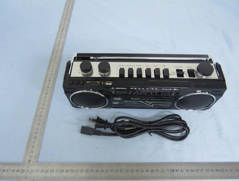
Click to zoom
Application Details
- Equipment Class
- DSS - Part 15 Spread Spectrum Transmitter
- Date of Grant
- Jan 17, 2020
- Application Purpose
- Original Equipment
- Date of Application
- Jan 17, 2020
- Equipment Note
- BLUETOOTH CASSETTE RADIO BOOMBOX
- Frequency Range
- 2402.00000000 - 2480.00000000
- Company
- LEOTEC ELECTRONICS CO.,LTD
- Country
- China
Documents & Files
Document Text
Text extracted from the exhibit documents filed with the FCC. Open a document above to read the original.
Users Manual
LOCATION OF CONTROLS 1.Speaker 2.Volume Control 3.Bass control 4.Tape Silo 5.Record Button 6.Play Button 7.Rewind Button 8.Fast Forward Button 9.Stop/Eject Button 10.Pause Button 11.Dial Scale 12.Function Switch 13.Band Switch 14.Tuning Control 15.Condenser Mic 16.Prev Button 17.Pause/Play Button 18.Next Button 19.Card 20.USB/Music Jack 21.AC Socket 12 3 4 56 7 8910 1112 13 14 15 16 17 181920 21 PAUSE FUNCTION During playback or recording, the tape can be stopped temporarily by depressing the PAUSE BUTTON. Press again to release the pause action. RECORDING Recording from the Built-in Microphone 1. Install a plain cassette. 2. Slide the FUNCTION SWITCH to TAPE position. 3. Depress RECORD BUTTON for recording. Recording from the BT, Card or USB. Turn the switch to BT/Music mode, depress RECORD BUTTON simultaneously. EXTERNAL HEADPHONE JACK For private listening, insert the plug of a headphone(not included)into HEADPHONE JACK and adjust VOLUME CONTROL accordingly. During the use of headphone, the built-in speaker is automatically disconnected. MAINTENANCE Cleaning of the Heads, Plinch Rollers and Capstans To assure continued high performance from our Recorder periodically. Cleaning the heads,pinch rollers and capstans whenever an accumulation of dust and tape oxide deposits.These particles may be cleaned with a cotton swab moistened with alcohol (methylated spirit) or special head-cleaning fluid. * Depress the STOP/EJECT BUTTON and remove the cassette. * Carefully rub the face of the heads and also the surface of the capstans and the pinch rollers. WARNING: To prevent fire or shock hazard, do not expose this appliance to rain or moisture. Do not remove cover(or back), no user serviceable parts inside. Refer servicing to qualified service personnel. FM/AM/SW1/SW2 4 BANDS BLUETOOTH CASSETTE RADIO BOOMBOX SRC232BT INSTRUCTION MANUAL For service assistance and product information, please call: 1-800-968-9853. Curtis International Ltd. 7045 BECKETT DRIVE, UNIT 15, MISSISSAUGA, ON, L5S 2A3 www.curtisint.com SYLVANIA is a registered trademark of OSRAM Sylvania Inc. used under license 13 45 DRY BATTERY(NOT INCLUDED): Opening the battery door can be installed in the four section "UM-1" or R20 of the battery. Note: before using the battery, disconnect the power cord from the AC power outlet. USAGE METHOD: 1.MP3 and Bluetooth partial function operation: a. Switch to BT/Music mode, inserted card or USB to the card slot or USB jack, it will play the songs from the card or USB. b. In the Bluetooth state can be connected to the phone after the phone music player, short press the play button to play and pause, long press the play button that it can switch card/USB or BT mode. c. Long press PLAY button to USB/ CARD, the USB or CARD to play the music, this Short press REW/NEXT for one song and the next song, long press rewind and fast forward. Note:Please do not pull out the USB/CARD when playing, please pause it or switch it to the other mode before pulling. Otherwise it may cause the card or USB damage, cannot play normally. 2. SWITCH RADIO FM LOCATION: a. Turn the volume to a moderate position, and then pushed the band button to the FM position, you can listen to FM band any radio program. b. Pushed to the SW band, and then twist the dial button, you can listen to any radio program in SW band. c. When receiving FM shortwave radio, please pull out the telescopic FM antenna to get better reception Result. 3. Function to switch to the radio station, to listen to the AM band: a. Push the function button to the AM position, and then turn the dial button, you can listen to the AM band any radio program. b. When receiving the radio signal is not good, please adjust the direction of the machine to get better Receive result. OPERATION OF MAGNTEIC TAPE CARTRIDGE: Open the recording room to press the stop / eject button, insert the record box, and then close the tape box door. PLAYBACKOPERATION: Function to switch to the tape position, press the play button, will begin to play; adjust the volume control to the required sound level. FAST FORWARD AND REWIND: To play a part or a part of the tape in a magnetic tape. Press stop / The eject button, then press the "fast forward button winding or rewind button and press stop / play Button stop tape. 6 To make a warranty claim, do not return this product to the store. Please email [email protected] or call 1-800-968-9853. 90 day Warranty This product is warranted to be free from defects in material and workmanship for a period of ninety (90) days from the date of original purchase. During this period, your exclusive remedy is repair or replacement of this product or component found to be defective, at our option; however, you are responsible for all costs associated with returning the product to us. If the product or component is no longer available, we will replace with a similar one of equal or greater value. Prior to a replacement being sent, the product must be rendered inoperable or returned to us. This warranty does not cover glass, filters, wear from normal use, use not in conformity with the printed directions., or damage to the product resulting from accident, alteration, abuse, or misuse. This warranty extends only to the original consumer purchaser or gift recipient. Keep the original sales receipt, as proof of purchase is required to make a warranty claim. This warranty is void if the product is used for other than single-family household use or subjected to any voltage and waveform other than as on the specified rating on the label (e.g., 120V~60Hz). We exclude all claims for special, incidental, and consequential damages caused by breach of express or implied warranty. All liability is limited to the amount of the purchase price. Every implied warranty, including any statutory warranty or condition of merchantability or fitness for a particular purpose, is disclaimed except to the extent prohibited by law, in which case such warranty or condition is limited …
Text truncated - open the document above for the full version.
External Photos
FCC ID: 2AHW8SRC232BT0 External photo FCC ID: 2AHW8SRC232BT0 FCC ID: 2AHW8SRC232BT0 FCC ID: 2AHW8SRC232BT0
ID Label/Location Info
Label & Location
Internal Photos
FCC ID: 2AHW8SRC232BT0 Internal photo FCC ID: 2AHW8SRC232BT0 FCC ID: 2AHW8SRC232BT0 FCC ID: 2AHW8SRC232BT0 BT Antenna BT Chip
Operational Description
LEOTEC ELECTRONICS CO.,LTD Declaration concerning Antenna Specification It is hereby declared that the product Model No.: SRC232BT, LT-BT400RUC FCC ID: 2AHW8SRC232BT0 fulfills the requirement in FCC test relating to the antenna type. The device specified above confirms to the FCC recommendations for internal antenna type(s) described below: Model No. of antenna: BT Antenna Type of antenna: permanently attached (PCB antenna) Gain of the antenna: -0.58 dBi Frequency range: 2402-2480 MHz The mounting of the antenna is fixed to the radio module and no other antenna should be used. Company name: LEOTEC ELECTRONICS CO.,LTD Address: No.106,Wentang North Road, Wenzhou Road,Dongcheng District, City: Dongguan ZIP / Postal code: N/A Country: China Place: Hao Chu Date: 2020-01-13 Signature:
RF Exposure Info
Dongguan Nore Testing Center Co., Ltd. Report No.: NTC1912177F-1 FCC ID: 2AHW8SRC232BT0 RF EXPOSURE EVALUATION EUT Specification EUT BLUETOOTH CASSETTE RADIO BOOMBOX Frequency band (Operating) WLAN: 2.412GHz ~ 2.462GHz WLAN: 5.18GHz ~ 5.32GHz / 5.50GHz ~ 5.70GHz WLAN: 5.745GHz ~ 5825GHz Others(Bluetooth: 2.402GHz ~ 2.480GHz) Device category Portable (<20cm separation) Mobile (>20cm separation) Others ___ Antenna diversity Single antenna Multiple antennas Tx diversity Rx diversity Tx/Rx diversity Max. output power -3.40dBm(0.46mW) Antenna gain -0.58dBi Evaluation applied MPE Evaluation SAR Evaluation Standard Requirement Portable Device According to §15.247(i) and §1.1307b(1), systems operating under the provisions of this section shall be operated in a manner that ensures that the public is not exposed to radio frequency energy levels in excess of the Commission’s guidelines. See KDB 447498 D01 General RF Exposure Guidance v05, section 4.3.1. The 1-g and 10-g SAR test exclusion thresholds for 100 MHz to 6 GHz at test separation distances ≤ 50 mm are determined by: [(max. power of channel, including tune-up tolerance, mW)/(min. test separation distance, mm)] ·[√f(GHz)] ≤ 3.0 for 1-g SAR and ≤ 7.5 for 10-g extremity SAR, 16 where ·f(GHz) is the RF channel transmit frequency in GHz ·Power and distance are rounded to the nearest mW and mm before calculation17 ·The result is rounded to one decimal place for comparison The test exclusions are applicable only when the minimum test separation distance is ≤ 50 mm and for transmission frequencies between 100 MHz and 6 GHz. When the minimum test separation distance is < 5 mm, a distance of 5 mm is applied to determine SAR test exclusion. Dongguan Nore Testing Center Co., Ltd. Report No.: NTC1912177F-1 FCC ID: 2AHW8SRC232BT0 Measurement Result Channel Channel Frequency (MHz) Max Output power (dBm) Max Output power (mW) Calculati on Value (Note 1) Threshold Value GFSK Low 2402 -4.748 0.34 0.105 3.0 Middle 2441 -4.025 0.40 0.125 3.0 High 2480 -4.211 0.38 0.120 3.0 π/4-DQPSK Low 2402 -4.058 0.39 0.121 3.0 Middle 2441 -3.400 0.46 0.144 3.0 High 2480 -3.603 0.44 0.139 3.0 Note 1: Calculation Value =[(max. power of channel, mW)/(min. test separation distance, mm)] ·[√f(GHz)]. Fox example: 0.46/5*√2.441=0.144 ≤ 3.0 According to KDB447498 D01 V06, threshold at which no SAR required is ≤3.0 for 1-g SAR, separation distance is 5mm, and no simultaneous SAR measurement is required.
Test Report
Dongguan Nore Testing Center Co., Ltd. Report No.: NTC1912177FV00 FCC ID: 2AHW8SRC232BT0 Page 2 of 49 Table of Contents 1. GENERAL INFORMATION ................................................................................................ 5 1.1 PRODUCT DESCRIPTION FOR EQUIPMENT UNDER TEST ................................................................. 5 1.2 RELATED SUBMITTAL(S) / GRANT (S) ............................................................................................ 8 1.3 TEST METHODOLOGY .................................................................................................................. 8 1.4 EQUIPMENT MODIFICATIONS ........................................................................................................ 8 1.5 SUPPORT DEVICE ....................................................................................................................... 8 1.6 TEST FACILITY AND LOCATION ..................................................................................................... 9 1.7 SUMMARY OF TEST RESULTS ..................................................................................................... 10 2. SYSTEM TEST CONFIGURATION .................................................................................. 11 2.1 EUT CONFIGURATION ............................................................................................................... 11 2.2 SPECIAL ACCESSORIES ............................................................................................................. 11 2.3 DESCRIPTION OF TEST MODES ................................................................................................... 11 2.4 EUT EXERCISE ......................................................................................................................... 11 3. CONDUCTED EMISSIONS TEST .................................................................................... 12 3.1 TEST SET-UP (BLOCK DIAGRAM OF CONFIGURATION) ................................................................ 12 3.2 TEST CONDITION ....................................................................................................................... 12 3.3 MEASUREMENT RESULTS .......................................................................................................... 12 4. RADIATED EMISSION TEST ........................................................................................... 15 4.1 TEST SET-UP (BLOCK DIAGRAM OF CONFIGURATION) ................................................................ 15 4.2 MEASUREMENT PROCEDURE ..................................................................................................... 16 4.3 LIMIT ........................................................................................................................................ 17 4.4 MEASUREMENT RESULTS ................................................................................................. 17 5. CHANNEL SEPARATION TEST ...................................................................................... 21 5.1 MEASUREMENT PROCEDURE ..................................................................................................... 21 5.2 TEST SET-UP (BLOCK DIAGRAM OF CONFIGURATION) ................................................................ 21 5.3 MEASUREMENT RESULTS .......................................................................................................... 21 6. 20DB BANDWIDTH .......................................................................................................... 25 6.1 MEASUREMENT PROCEDURE ..................................................................................................... 25 6.2 TEST SET-UP (BLOCK DIAGRAM OF CONFIGURATION) ................................................................ 25 6.3 MEASUREMENT RESULTS .......................................................................................................... 25 7. HOPPING CHANNEL NUMBER ...................................................................................... 29 7.1 MEASUREMENT PROCEDURE ..................................................................................................... 29 7.2 TEST SET-UP (BLOCK DIAGRAM OF CONFIGURATION) ................................................................ 29 7.3 MEASUREMENT RESULTS .......................................................................................................... 29 Dongguan Nore Testing Center Co., Ltd. Report No.: NTC1912177FV00 FCC ID: 2AHW8SRC232BT0 Page 3 of 49 8. TIME OF OCCUPANCY (DWELL TIME) .......................................................................... 31 8.1 MEASUREMENT PROCEDURE ..................................................................................................... 31 8.2 MEASUREMENT RESULTS .......................................................................................................... 31 9. MAXIMUM PEAK OUTPUT POWER ............................................................................... 35 9.1 MEASUREMENT PROCEDURE ..................................................................................................... 35 9.2 MEASUREMENT RESULTS .......................................................................................................... 35 10. BAND EDGE AND RESTRICTION BANDS ................................................................... 39 10.1 MEASUREMENT PROCEDURE ................................................................................................. 39 10.2 LIMIT .................................................................................................................................... 39 10.3 MEASUREMENT RESULTS ...................................................................................................... 39 11. ANTENNA APPLICATION .............................................................................................. 44 11.1 ANTENNA…
Text truncated - open the document above for the full version.
Test Setup Photos
FCC ID: 2AHW8SRC232BT0 Test photo Radiated emission Below 30MHz 30MHz-1GHz FCC ID: 2AHW8SRC232BT0 Above 1GHz Conducted emission
Contact Information
Applicant
Hao Chu
Test Firm
Dongguan NTC CO., Ltd.Jees Hong
[email protected]+86-769-22022444
Technical Specifications
| # | Rule Parts | Frequency Range | Power Output |
|---|---|---|---|
| 1 | 15C | 2.40 GHz - 2.48 GHz | 460.00 µW |
Other Applications from LEOTEC ELECTRONICS CO.,LTD
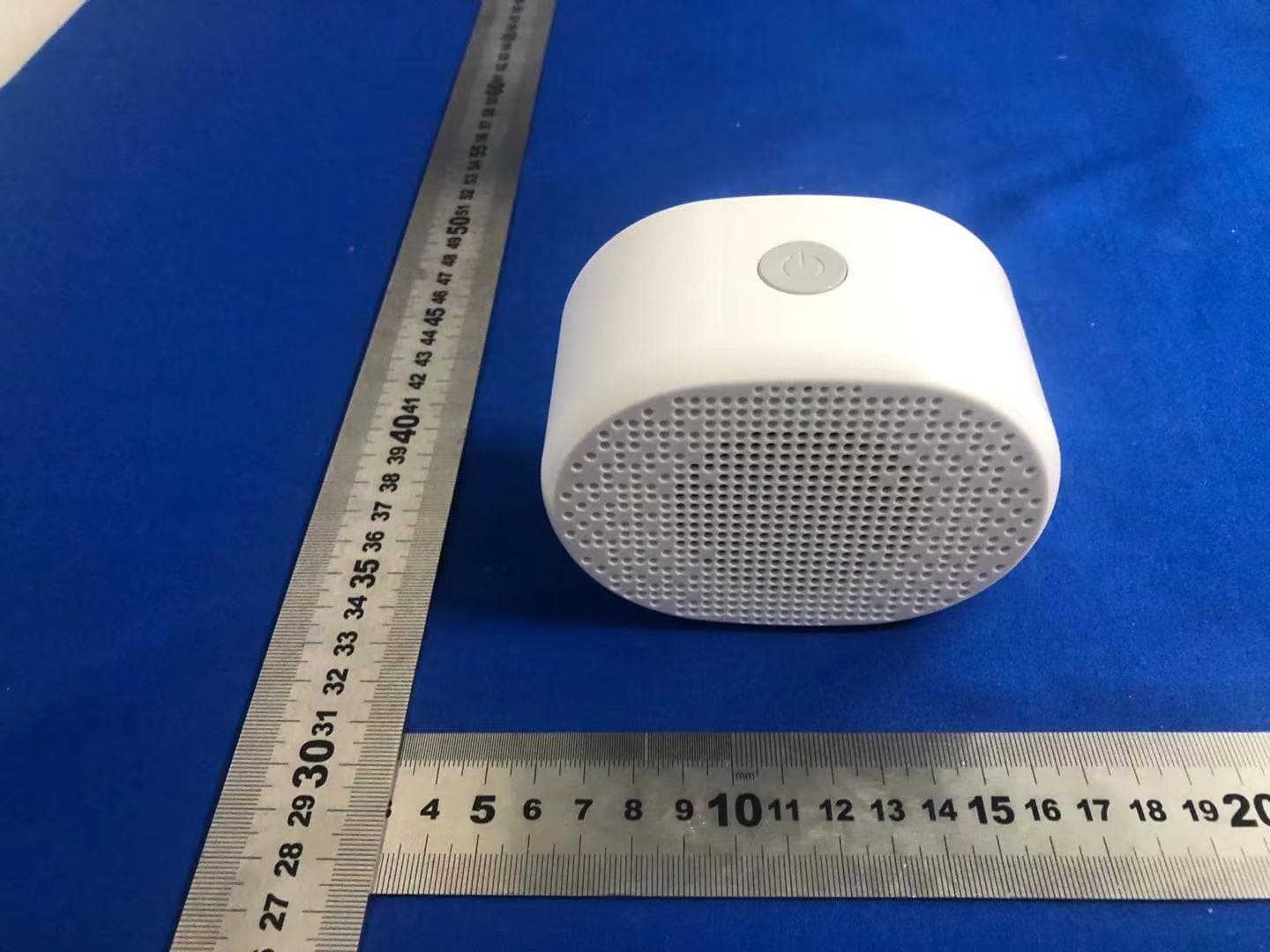
2AHW8LT02
Apr 25, 2021Bluetooth Speaker
Equipment Class
DXX - Part 15 Low Power Communication Device Transmitter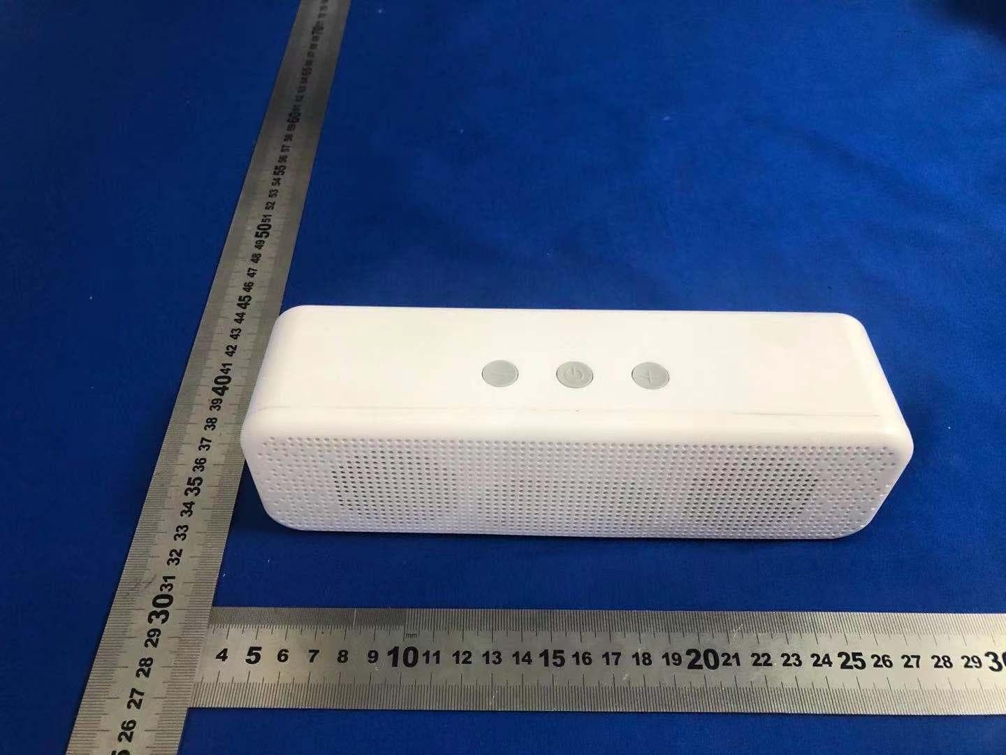
2AHW8LT01
Apr 25, 2021Bluetooth Speaker
Equipment Class
DXX - Part 15 Low Power Communication Device Transmitter