2AIGCWFB004Wireless HVAC Controller
MITSUBISHI ELECTRIC US, INC.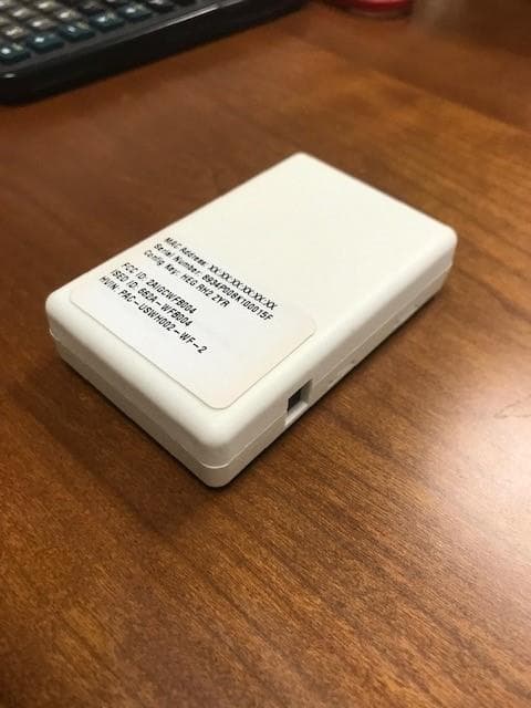
Click to zoom
Application Details
- Equipment Class
- DTS - Digital Transmission System
- Date of Grant
- May 01, 2023
- Application Purpose
- Original Equipment
- Date of Application
- May 01, 2023
- Equipment Note
- Wireless HVAC Controller
- Frequency Range
- 2412.00000000 - 2462.00000000
- Company
- MITSUBISHI ELECTRIC US, INC.
- Country
- United States
Documents & Files
Document Text
Text extracted from the exhibit documents filed with the FCC. Open a document above to read the original.
Users Manual
Specifications are subject to change without notice. 1 © 2023 Mitsubishi Electric US, Inc. MANUFACTURED FOR: MITSUBISHI ELECTRIC US, INC. PAC-USWHS002-WF-2 1. About Wireless Interface 2 Wireless Interface 2 allows the kumo cloud ® app to communicate with and control the air conditioner remotely. To enable this communication and control, Wireless Interface 2 needs to be configured with a wireless router connected to the internet. ATTENTION • The Wireless Interface 2 must connect to a 2.4 GHz Wi-Fi network. • The Wireless Interface 2 will not work on a 5 GHz Wi-Fi network. •The Wireless Interface can only connect to Wi-Fi channels 1-11. • For the best performance connect the Wireless Interface to a 2.4 GHz only SSID, but there are some multi-band Wi-Fi networks that can correctly manage a 2.4 GHz only device. •Please verify if your multi-band Wi-Fi router can manage 2.4 GHz only devices. • Some room air conditioners are not compatible with the Wireless Interface 2. Make sure that the room air conditioner is compatible with the Wireless Interface 2 before attempting to install it. INSTALLATION/INSTRUCTION MANUAL Before using the device, carefully read this installation/instruction manual to ensure proper operation. Keep this manual for future reference and give it to the technician when the device is reinstalled or repaired. FOR INSTALLER Wireless Interface 2 Contents 1. About Wireless Interface 2................................................................................1 2. Safety Instructions ............................................................................................2 3. What’s in the Box ..............................................................................................5 4. Parts .................................................................................................................5 5. Connecting the Wireless Interface 2 to the Indoor Unit ....................................6 6. Specifications....................................................................................................7 Specifications are subject to change without notice. 2 © 2023 Mitsubishi Electric US, Inc. Do not use the red 5-pin connector to create an unsupported equipment combination. Unsupported equipment combinations may result in fire, electric shock and/or damage/water leaks. Refer to the Wireless Interface 2 compatibility guide for more details. • Users should not install the Interface on their own. Improper installation may result in fire, electric shock or damage/water leaks. Consult the dealer from whom you purchased the unit or a professional installer. • The Interface should be securely installed in accordance with this installation manual. Improper installation may result in fire, electric shock or damage. • The unit should be mounted in a location that can support its weight. If the unit is installed in a location that cannot support its weight, the Wireless Interface 2 could fall and cause damage. Install securely in a place where the Wireless Interface 2 does not interfere with equipment operation or serviceability. Improper installation may result in fire, electric shock or damage/water leaks. • Do not install Wireless Interface 2 inside a metal enclosure. Improper installation may result in diminished signal strength. • Connect and fasten the electric wires securely so external force on the wires will not apply on the terminals. Improper connection and mounting may result in breakdown, heat generation, smoke generation or fire. • Mitsubishi components or other designated components must be used for installation. Improper component may result in fire, electric shock or damage/water leaks. • Electrical work must be performed by a licensed professional using the instructions detailed in the installation manual. Inadequate circuit capacity or improper installation may result in electric shock or fire. Warning 2. Safety Instructions • Read all Safety Instructions before using the Wireless Interface 2. • This installation manual contains important safety information. Be sure to comply with the instructions. Warning Improper handling may have serious consequences, including serious injury or death. Caution Improper handling may have consequences, including injury or damage to house. • After installing the Wireless Interface 2, provide this installation manual to the user. Instruct users to store it with their room air conditioner instruction manual in a safe location. Specifications are subject to change without notice. 3 © 2023 Mitsubishi Electric US, Inc. Warning • This appliance is not intended for use by persons (including children) with reduced physical, sensory or mental capabilities, or lack of experience and knowledge, unless they have been given supervision or instruction concerning use of the appliance by a person responsible for their safety. • Children should be supervised to ensure that they do not play with the appliances. • This device complies with part 15 of the FCC Rules. Operation is subject to the following two conditions: (1) This device may not cause harmful interference, and (2) This device must accept any interference received, including interference that may cause undesired operation. • This equipment has been tested and found to comply with the limits for a Class B digital device, pursuant to part 15 of the FCC Rules. These limits are designed to provide reasonable protection against harmful interference in a residential installation. This equipment generates, uses and can radiate radio frequency energy and, if not installed and used in accordance with the instructions, may cause harmful interference to radio communications. However, there is no guarantee that interference will not occur in a particular installation. If this equipment does cause harmful interference to radio or television reception, which can be determined by turning the equipment off and on, the user is encouraged to try to correct the interference by one or more …
Text truncated - open the document above for the full version.
Cover Letter(s)
TUV SUD America, 5945 Cabot Parkway, Suite 100, Alpharetta GA 30005 Document: 120780 v1 Page 1 of 1 Date: April 17, 2023 Federal Communications Commission Laboratory 7435 Oakland Mills Road Columbia, MD 21046 Re: FCC ID: 2AIGCWFB004 To Whom It May Concern: The following application is submitted on behalf of our client, Mitsubishi Electric US, Inc., for evaluation of their model PAC-USWHS002-WF-2 for a new certification under FCC Part 15.247. The device is a wireless HVAC controller. I have reviewed the application and supporting documentation and have found them to comply with FCC requirements. I recommend this application for certification. Yours sincerely Jeff Woods TUV SUD Senior Engineer
External Photos
Figure 1: View 1 Figure 2: View 2 Figure 3: View 3 Figure 4: View 4
RF Exposure Info
5945 Cabot Parkway Suite 100 Alpharetta, GA 30005 USA Certification Exhibit FCC ID: 2AIGWFB004 FCC Rule Part: 47 CFR Part 2.1091 Project Number: 72185560 Manufacturer: Murata Electronics North America Model Name/Number: PAC-USWHS002-WF-2 RF Exposure Model Name/Number: PAC- USWHS002-WF-2 FCC ID: 2AIGWFB004 Report: AT72185560-3C1 Page 2 General Information: Applicant: Mitsubishi HVAC US Device Category: Mobile Environment: General Population/Uncontrolled Exposure Technical Information (BLE) – “Device 1”: Frequency Range (MHz): 2402 - 2480 Antenna Type: PCB Antenna Antenna Gains: 3.3 dBi Maximum Transmitter Conducted Power: 7.71dBm, 5.90mW Maximum System EIRP: 11.01dBm, 12.62mW Exposure Conditions: 20 centimeters Technical Information (Wi-Fi 2.4 GHz IEEE 802.11 b/g/n) – “Device 2”: Frequency Range (MHz): 2412 - 2462 Antenna Type: PCB Antenna Antenna Gains: 3.3 dBi Maximum Transmitter Conducted Power: 24.21dBm, 263.63mW Maximum System EIRP: 27.51dBm, 563.64mW Exposure Conditions: 20 centimeters Note: The device does not support simultaneous transmissions RF Exposure Calculation Table 1: Device Characteristics Technical Parameters Device 1 Device 2 Frequency Range (GHz) 2.402 – 2.480 2.412 – 2.462 Frequency Range (MHz) 2402 - 2480 2412 - 2462 Separation Distance (cm) 20.00 20.0 Separation Distance (m) 0.2000 0.200 Antenna Gain (dBi) 3.30 3.30 ERP Easily Determined YES YES Conducted Power (dBm) 7.71 24.21 Conducted Power (mW) 5.90 263.63 Duty Factor (Source-Based) % 100.0 100.0 Maximum (Source-Based) Time-Averaged Conducted Power (mW) 5.90 263.63 Maximum (Source-Based) Time-Averaged ERP (mW) 7.69 343.68 Maximum (Source-Based) Time-Averaged EIRP (mW) 12.62 563.64 Maximum Output (mW) 7.69 343.68 Model Name/Number: PAC-USWHS002-WF-2 FCC ID: 2AIGWFB004 Report: AT72185560-3C1 Page 3 Table 2: 47 CFR 1.1307(b)(3)(i)(C) MPE-Based Exemption ERP (W) Technical Parameters Device 1 Device 2 λ / 2π (m) 0.019 0.019 R≥ λ / 2π YES YES Maximum (Source-Based) Time-Averaged ERP (W) 0.0077 0.3437 ERP Threshold (W) 0.7680 0.7680 Exemption YES YES
Test Report
MEUS Inverted F Antenna Specification The MEUS WiFi-BLE adapter board uses an integrated Inverted-F antenna. This antenna is designed into the PCB and cannot be modified or removed by the end user. The antenna design was taken directly from App Note DN0007 by Texas Instruments without modification. The specification below is taken from measured results in our lab and directly from the DN0007 App Note. Antenna Design and Layout: Measured Antenna Impedance Match and Return Loss: Antenna Patterns: Summary of Antenna Performance:
Test Report
TÜV SÜD America 5945 Cabot Parkway, Suite 100 Alpharetta, GA 3005 Phone: 678-341-5900 www.tuv-sud-america.com TÜV SÜD SIGNATURE NAME JOB TITLE RESPONSIBLE FOR ISSUE DATE Kirby Munroe Wireless / EMC Technical and Certification Manager, NA TUV SUD America Inc. Authorized Signatory 5/1/2023 Signatures in this approval box have checked this document in line with the requirements of TÜV SÜD America, Inc. document control rules. FCC Accreditation Designation Number US1233 FCC Test Site Registration Number 967699 Innovation, Science, and Economic Development Canada Lab Code 23932 EXECUTIVE SUMMARY A sample of this product was tested and found to be compliant with the standards listed above. A2LA Cert. No. 2955.09 DISCLAIMER AND COPYRIGHT This non-binding report has been prepared by TÜV SÜD America with all reasonable skill and care. The document is confidential to the potential Client and TÜV SÜD America. No part of this document may be reproduced without the prior written approval of TÜV SÜD America. © TÜV SÜD. ACCREDITATION Our A2LA Accreditation does not cover opinions and interpretations and any expressed are outside the scope of our A2LA Accreditation. Report on the Testing of the Mitsubishi Electric US PAC-USWHS002-WF-2 In accordance with: FCC 47 CFR part 15.247 ISED RSS-247 Issue 2, February 2017 Prepared for: MuRata Electronics North America 2200 Lake Park Drive Smyrna, Georgia 30080 USA COMMERCIAL-IN-CONFIDENCE Document Number: AT72185560.1C1 Document Number: AT72185560.1C1 COMMERCIAL-IN-CONFIDENCE Page 2 of 42 Contents Report Summary .........................................................................................................................3 Report Modification Record ...........................................................................................................3 Introduction ....................................................................................................................................3 Brief Summary of Results .............................................................................................................5 Product Information .......................................................................................................................6 Deviations from the Standard ........................................................................................................9 EUT Modification Record ..............................................................................................................9 Test Location .............................................................................................................................. 10 Test Details ............................................................................................................................... 11 Antenna Requirement ................................................................................................................ 11 Power Line Conducted Emissions ............................................................................................. 12 Fundamental Emission Output Power ........................................................................................ 17 6dB / 99% Bandwidth ................................................................................................................. 19 Maximum Power Spectral Density in the Fundamental Emission ............................................. 25 Band-Edge Compliance of RF Conducted Emissions ............................................................... 28 RF Conducted Spurious Emissions ........................................................................................... 30 Radiated Spurious Emissions into Restricted Frequency Bands ............................................... 32 Test Equipment Used ................................................................................................................. 39 Diagram of Test Set-ups .......................................................................................................... 40 Accreditation, Disclaimers and Copyright............................................................................. 42 Document Number: AT72185560.1C1 COMMERCIAL-IN-CONFIDENCE Page 3 of 42 Report Summary Report Modification Record Alterations and additions to this report will be issued to the holders of each copy in the form of a complete document. Table 1.1-1 – Modification Record Issue Description of Change Date of Issue 0 First Issue 2/2/2023 1 Second Issue 5/1/2023 Introduction The purpose of this report is to demonstrate compliance with Part 15 Subpart C of the FCC’s Code of Federal Regulations Section 15.247 and Innovation Science and Economic Development Canada’s Radio Standards Specification RSS-247 for the tests documented herein. Applicant Applicant Company Rodney Olson Mitsubishi Electric US Manufacturer Murata Electronics North America Applicant’s Email Address [email protected] Model Name / Number PAC-USWHS002-WF-2 Serial Number N/A FCC ID 2AIGWFB004 ISED Certification Number 31190-WFB004 Hardware Version(s) 3 Software Version(s) 3 Number of Samples Tested 2 Test Specification/Issue/Date US Code of Federal REgulation (CFR): Title 47, Part 15, Subpart C: Radio Frequency Devices, Intentional Radiators, 2022 ISED Canada Radio Standards Specification: RSS-247 – Digital Transmission Systems (DTSs), Frequency Hopping Systems (FHSs) and License-Exempt Local Area Network (LE-LAN) Devices, Issue 2, February 2017. Order Number 72185560 Date of Receipt of EUT 12/12/2022 Start of Test 12/12/2022 Finish of Test 1/5/2023 Document Number: AT72185560.1C1 COMMERCIAL-IN-CONFIDENCE Page 4 of 42 Related Document(s) ANSI C63.10-2013: American National Standard of Procedures for Compliance Testing of Unlicensed Wireless Device. FCC OET KDB 558074 D01 15.247 Meas Guidance v05r02: Guidance for Compliance Measurements on Digital Transmission System, Frequency Hopping Spread Spectrum System, and Hybrid System Dev…
Text truncated - open the document above for the full version.
Test Report
TÜV SÜD America 5945 Cabot Parkway, Suite 100 Alpharetta, GA 3005 Phone: 678-341-5900 www.tuv-sud-america.com TÜV SÜD SIGNATURE NAME JOB TITLE RESPONSIBLE FOR ISSUE DATE Kirby Munroe Wireless / EMC Technical and Certification Manager, NA TUV SUD America Inc. Authorized Signatory 5/1/2023 Signatures in this approval box have checked this document in line with the requirements of TÜV SÜD America, Inc. document control rules. FCC Accreditation Designation Number US1233 FCC Test Site Registration Number 967699 Innovation, Science, and Economic Development Canada Lab Code 23932 EXECUTIVE SUMMARY A sample of this product was tested and found to be compliant with the standards listed above. A2LA Cert. No. 2955.09 DISCLAIMER AND COPYRIGHT This non-binding report has been prepared by TÜV SÜD America with all reasonable skill and care. The document is confidential to the potential Client and TÜV SÜD America. No part of this document may be reproduced without the prior written approval of TÜV SÜD America. © TÜV SÜD. ACCREDITATION Our A2LA Accreditation does not cover opinions and interpretations and any expressed are outside the scope of our A2LA Accreditation. Report on the Testing of the Mitsubishi Electric US PAC-USWHS002-WF-2 In accordance with: FCC 47 CFR part 15.247 ISED RSS-247 Issue 2, February 2017 Prepared for: MuRata Electronics North America 2200 Lake Park Drive Smyrna, Georgia 30080 USA COMMERCIAL-IN-CONFIDENCE Document Number: AT72185560.2C1 Document Number: AT72185560.2C1 COMMERCIAL-IN-CONFIDENCE Page 2 of 60 Contents Report Summary .........................................................................................................................3 Report Modification Record ...........................................................................................................3 Introduction ....................................................................................................................................3 Brief Summary of Results .............................................................................................................5 Product Information .......................................................................................................................6 Deviations from the Standard ........................................................................................................9 EUT Modification Record ..............................................................................................................9 Test Location .............................................................................................................................. 10 Test Details ............................................................................................................................... 11 Antenna Requirement ................................................................................................................ 11 Power Line Conducted Emissions ............................................................................................. 12 Fundamental Emission Output Power ........................................................................................ 17 6dB / 99% Bandwidth ................................................................................................................. 19 Maximum Power Spectral Density in the Fundamental Emission ............................................. 31 Band-Edge Compliance of RF Conducted Emissions ............................................................... 39 RF Conducted Spurious Emissions ........................................................................................... 43 Radiated Spurious Emissions into Restricted Frequency Bands ............................................... 47 Test Equipment Used ................................................................................................................. 57 Diagram of Test Set-ups .......................................................................................................... 58 Accreditation, Disclaimers and Copyright............................................................................. 60 Document Number: AT72185560.2C1 COMMERCIAL-IN-CONFIDENCE Page 3 of 60 Report Summary Report Modification Record Alterations and additions to this report will be issued to the holders of each copy in the form of a complete document. Table 1.1-1 – Modification Record Issue Description of Change Date of Issue 0 First Issue 2/2/2023 1 Second Issue 5/1/2023 Introduction The purpose of this report is to demonstrate compliance with Part 15 Subpart C of the FCC’s Code of Federal Regulations Section 15.247 and Innovation Science and Economic Development Canada’s Radio Standards Specification RSS-247 for the tests documented herein. Applicant Applicant Company Rodney Olson Mitsubishi Electric US Manufacturer Murata Electronics North America Applicant’s Email Address [email protected] Model Name/Number PAC-USWHS002-WF-2 Serial Number N/A FCC ID 2AIGWFB004 ISED Certification Number 30119-WFB004 Hardware Version(s) 3 Software Version(s) 3 Number of Samples Tested 2 Test Specification/Issue/Date US Code of Federal REgulation (CFR): Title 47, Part 15, Subpart C: Radio Frequency Devices, Intentional Radiators, 2022 ISED Canada Radio Standards Specification: RSS-247 – Digital Transmission Systems (DTSs), Frequency Hopping Systems (FHSs) and License-Exempt Local Area Network (LE-LAN) Devices, Issue 2, February 2017. Order Number 72185560 Date of Receipt of EUT 12/12/2022 Start of Test 12/12/2022 Finish of Test 1/5/2023 Document Number: AT72185560.2C1 COMMERCIAL-IN-CONFIDENCE Page 4 of 60 Related Document(s) ANSI C63.10-2013: American National Standard of Procedures for Compliance Testing of Unlicensed Wireless Device. FCC OET KDB 558074 D01 15.247 Meas Guidance v05r02: Guidance for Compliance Measurements on Digital Transmission System, Frequency Hopping Spread Spectrum System, and Hybrid System Devic…
Text truncated - open the document above for the full version.
Test Setup Photos
5945 Cabot Parkway Suite 100 Alpharetta, GA 30005 USA Certification Exhibit FCC ID: 2AIGWFB004 IC: 30119-WFB004 FCC Rule Part: 15.247 ISED Canada Radio Standards Specification: RSS-247 Project Number: 72185560 Manufacturer: MuRata Electronics North America. Model Name/Number: PAC-USWHS002-WF-2 Test Setup Photos 5945 Cabot Parkway Suite 100 Alpharetta, GA 30005 USA Figure 1 – Test Set up - Radiated Emissions <30 MHz Figure 2 – Test Set up - Radiated Emissions <1 GHz 5945 Cabot Parkway Suite 100 Alpharetta, GA 30005 USA Figure 3 – Test Set up - Radiated Emissions <10 GHz Figure 4 – Test Set up - Radiated Emissions <18 GHz 5945 Cabot Parkway Suite 100 Alpharetta, GA 30005 USA Figure 5 – Test Set up - Radiated Emissions >18 GHz Figure 6 – Test Set up – Conducted Emissions – 12V Power Supply 5945 Cabot Parkway Suite 100 Alpharetta, GA 30005 USA Figure 7– Test Set up – Conducted Emissions – 5V Power Supply Figure 8 – Test Set up – Antenna Port Measurement
Contact Information
Applicant
Rodney Olson(Senior Director, Controls Engineering)
Test Firm
TUV SUD America, Inc.William Elliott
[email protected]813-284-2736
Technical Specifications
| # | Rule Parts | Frequency Range | Power Output |
|---|---|---|---|
| 2 | 15C | 2.41 GHz - 2.46 GHz | 266.00 mW |