2AIHFZYCR127CRANE-M3S Camera Stabilizer
Guilin Zhishen Information Technology Co.,Ltd.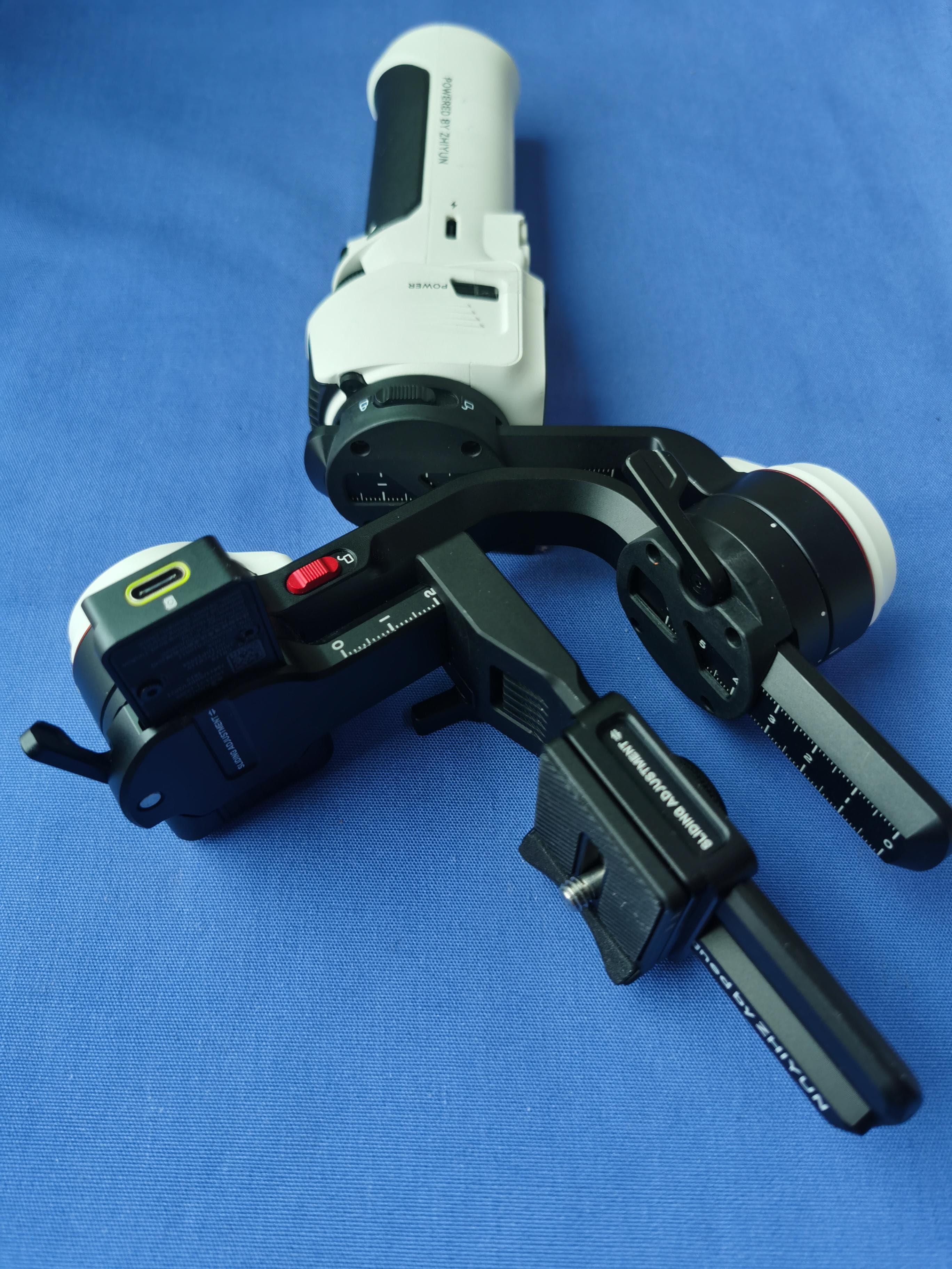
Click to zoom
Application Details
- Equipment Class
- JAB - Part 15 Class B Digital Device
- Date of Grant
- May 18, 2023
- Application Purpose
- Original Equipment
- Date of Application
- May 12, 2023
- Equipment Note
- CRANE-M3S Camera Stabilizer
- Country
- China
Documents & Files
Document Text
Text extracted from the exhibit documents filed with the FCC. Open a document above to read the original.
Users Manual
Quick Keyword Search Enter the keyword in the search box and hit the search button Quick Jump between Chapters Click the title of a specific chapter on the Contents to jump to it The following features are available in this PDF document. *Reading software such as Adobe Reader is needed to support the functions above. CRANE-M 3S User Guide Model:CR127 ZHIYUN-EN-v1.00 Contents ■ ■ Product■List Product■List■······················1 ■ ■ Get■to■Know■CRANE-M■3S Get■to■Know■CRANE-M■3S■ ················3 ■ ■ Battery■and■Charging Battery■and■Charging■··················4 ■ ■ Mounting■and■Balancing Mounting■the■Tripod■ ··················5 Mounting■the■Camera■··················5 Mounting■the■Smartphone■ ···············9 Mounting■the■Action■Camera■···············10 Balancing■·······················12 ■ ■ How■to■Use■CRANE-M■3S Button■Description■···················14 Touchscreen■Introduction■················15 Touchscreen■Menu■···················16 Motor■Torque■Adjustment■················18 Bluetooth■Shutter■Control■················20 Gimbal■Modes■Description■················21 Manual■Reposition■···················25 ■ ■ How■to■Use■the■App Download■the■App■ ···················26 How■to■Connect■ ····················26 ZY■Play■Feature■Description■ ···············28 ■ ■ Firmware■Upgrade■&■Calibration Circumstances■When■Calibration■Is■Needed■ ········29 Six-side■Calibration■···················29 Motor■Fine-tuning■ ···················32 Firmware■Upgrade■ ···················32 ■ ■ Product■Specifications ■ ■ Disclaimer■and■Warning Reading■Tips■ ·····················36 WARNING■·······················37 Safe■Operation■Guidelines■················37 ■ ■ Warranty■Card Warranty■Period■ ····················38 Warranty■Exclusions■ ··················38 Warranty■Claim■Procedure■················38 ■ ■ Contact■Card 1 Product List Product List Before using this product, please check carefully that all the following items are included in the product package. In case that any item is found missing, please contact ZHIYUN or your local selling agent. CRANE-M 3S x 1USB Type-C Cable x 1 Type-C to Micro USB LN-MBUC-B02 Camera Control Cable x1 Type-C to Type-C USB LN-UCUC-D07 Camera Control Cable x1 Type-C to Multi USB LN-UCUS-C02 Camera Control Cable x1 Tripod x1* Tripod x1**Phone Clamp x1** 2 Product List Backpack x1**Quick Start Guide x1 Items marked “*” are included in CRANE-M 3S. Items marked “**” are included in CRANE-M 3S COMBO. 3 Get to Know CRANE-M 3S Get to Know CRANE-M 3S 1. 1/4"Camera Lock Screw 2.Quick Release Plate 3.Quick Release Plate Leveling Base 4.Level Mount 5.Leveling Base Lock Screw 6.Quick Release Plate Safety Lock 7.Pan Axis Motor 8.Pan Axis Latch 9. 1/4"Threaded Hole 10.Fill Light Control Wheel 11.Gimbal Handle 12.Tripod 13.Tilt Axis Latch 14.Camera Control/Charging Port 15.Tilt Axis Lock Switch 16.Roll Axis Latch 17.Roll Axis Motor 18.Roll Axis Lock Switch 19.Touchscreen 20.Mode Switch 21.Photo/Video Button 22. Joystick 23.Tilt Axis Motor 24.Level Mount Lock Screw 25.Pan Axis Lock Switch 26.Power Button 27.Type-C Charging/Firmware Upgrade Port 28.Fill Light 29.Adjustment Wheel 30.Trigger Button 盫 盬 盭 目 盯 盰 盱 盲 盳 盫盪 盫盫 盫盬 盫盭 盫目 盫盰 盫盱 盫盲 盫盳 盬盪 盬盫 盬盬 盫盯 盬盲 盭盪 盬盳 盬盭 盬目 盬盯 盬盰 盬盱 4 Battery and Charging CRANE-M 3S is equipped with built-in battery. When using CRANE-M 3S for the first time, please fully charge the battery to activate them and to ensure the proper function of the gimbal. Charging method: Use provided USB Type-C cable to connect the USB charger (not provided, recommend chargers that meet the USB Power Delivery Specification, supports 12W at most) to the charging port of CRANE-M 3S. Battery and Charging AC Power (100-240V) USB Charger USB Type-C Cable ① USB charger is not provided. ② Please power off CRANE-M 3S to charge. 5 Mounting and Balancing Mount the tripod to the bottom of the CRANE-M 3S handle, then unfold the tripod and place the CRANE-M 3S on a flat surface. Mounting the Tripod Mounting the Camera ① Please mount the camera before powering on CRANE-M 3S and balance the gimbal. Do not power on CRANE-M 3S when there’s no camera mounted on it. ② Before mounting the camera, make sure it is prepared ahead of time. Remove the lens cap and make sure the camera’s battery and memory card are already in place. ③ Each axis of the gimbal is equipped with a lock switch. You can use these lock switches to lock the axes for convenient installation and storage. The storage state is the default state. Please toggle the lock switch to unlock the three axes, expand the gimbal as shown in the image, and lock the axes again for convenient camera installation. 6 Lock state for storage Lock state for installation Mounting and Balancing 7 Mounting and Balancing 1. Hold down the quick release plate safety lock ① and remove the quick release plate from the quick release plate leveling base ② , then install the camera onto the quick release plate ③ . Install the camera and quick release plate as a whole onto the leveling base ④ , and the quick release plate safety lock will automatically lock. ① ② ③ ④ 8 Mounting and Balancing To remove, push the quick release plate safety lock to the unlock position ① , and the camera and quick release plate assembly can be removed as a whole ② . ① ② 2. Connect the camera control cable to the camera control port and the camera/image transmission control port of the gimbal. There are four camera control cables: Type-C to Multi USB/Type-C to Type-C USB / Type-C to Micro USB / Type-C to Mini USB. Choose the correct cable corresponding to the USB port type of the camera. For compatibility details, please visit the official website of ZHIYUN (www.zhiyun-tech.com) and check the CRANE-M 3S Camera Compatibility List. 9 Mounting and Balancing Hold down the quick release plate safety lock ① and remove the quick release plate from the quick release plate leveling base ② , then install the phone onto the phone clamp ③ . Install the phone and phone clamp as a whole onto the quick release plate ④…
Text truncated - open the document above for the full version.
Test Report
13 TEST REPORT No.I23N00229-EMC for Guilin Zhishen Information Technology Co., Ltd. CRANE-M 3S Model Name:CR127 With Hardware Version: V1.0 Software Version: V1.54 FCC ID:2AIHFZYCR127 Issued Date: 2023-04-13 Designation Number: CN1210 Note: The test results in this test report relate only to the devices specified in this report. This report shall not be reproduced except in full without the written approval of SAICT. Test Laboratory: SAICT, Shenzhen Academy of Information and Communications Technology Building G, Shenzhen International Innovation Center, No.1006 Shennan Road, Futian District, Shenzhen, Guangdong, P. R. China. 518000. Tel:+86(0)755-33322000, Fax:+86(0)755-33322001 Email: [email protected]. www.saict.ac.cn No. I23N00229-EMC ©Copyright. All rights reserved by SAICT. Page 2 of 23 REPORT HISTORY Report Number Revision Description Issue Date I23N00229-EMC Rev.0 1st edition 2023-04-13 Note: the latest revision of the test report supersedes all previous version. No. I23N00229-EMC ©Copyright. All rights reserved by SAICT. Page 3 of 23 CONTENTS 1. SUMMARY OF TEST REPORT ........................................................................................................ 4 1.1. TEST ITEMS ............................................................................................................................. 4 1.2. TEST STANDARDS .................................................................................................................. 4 1.3. TEST RESULT .......................................................................................................................... 4 1.4. TESTING LOCATION ............................................................................................................... 4 1.5. PROJECT DATA ....................................................................................................................... 4 1.6. SIGNATURE.............................................................................................................................. 4 2. CLIENT INFORMATION ........................................................................................................... 5 2.1. APPLICANT INFORMATION ................................................................................................... 5 2.2. MANUFACTURER INFORMATION ......................................................................................... 5 3. EQUIPMENT UNDER TEST (EUT) AND ANCILLARY EQUIPMENT (AE) ............................ 6 3.1. ABOUT EUT ............................................................................................................................. 6 3.2. INTERNAL IDENTIFICATION OF EUT .................................................................................... 6 3.3. INTERNAL IDENTIFICATION OF AE ...................................................................................... 6 3.4. EUT SET-UPS ........................................................................................................................... 8 3.5. GENERAL DESCRIPTION ....................................................................................................... 9 4. REFERENCE DOCUMENTS .................................................................................................. 10 4.1. REFERENCE DOCUMENTS FOR TESTING ........................................................................ 10 5. LABORATORY ENVIRONMENT.............................................................................................11 6. SUMMARY OF TEST RESULTS ............................................................................................ 12 6.1. TESTING ENVIRONMENT ..................................................................................................... 12 6.2. SUMMARY OF MEASUREMENT RESULTS ......................................................................... 12 6.3. STATEMENT ........................................................................................................................... 12 7. MEASUREMENT UNCERTAINTY ......................................................................................... 13 ANNEX A: MEASUREMENT RESULTS ....................................................................................... 14 A.1 RADIATED EMISSION (§15.109(A)) ...................................................................................... 14 A.2 CONDUCTED EMISSION (§15.107(A)).................................................................................. 20 No. I23N00229-EMC ©Copyright. All rights reserved by SAICT. Page 4 of 23 1. SUMMARY OF TEST REPORT 1.1. Test Items Description CRANE-M 3S Model Name Code Name CR127 CR127 Applicant’s name Guilin Zhishen Information Technology Co., Ltd. Manufacturer's Name Guilin Zhishen Information Technology Co., Ltd. 1.2. Test Standards FCC Part 15, Subpart B (10-1-2021 Edition); ANSI C63.4-2014. 1.3. Test Result Total test 2 items, pass 2 items. Please refer to “6.2 Test Results”. 1.4. Testing Location Address: Building G, Shenzhen International Innovation Center, No.1006 Shennan Road, Futian District, Shenzhen, Guangdong, China 1.5. Project data Testing Start Date: 2023-03-15 Testing End Date: 2023-03-20 1.6. Signature Liu Xiangzhou (Prepared this test report) Liang Yong (Reviewed this test report) Cao Junfei (Approved this test report) No. I23N00229-EMC ©Copyright. All rights reserved by SAICT. Page 5 of 23 2. CLIENT INFORMATION 2.1. Applicant Information Company Name: Guilin Zhishen Information Technology Co., Ltd. Address: 09 Huangtong Road, Tieshan Industrial Zone, Qixing District, Guilin, Guangxi, China. Contact Zou Jian Email [email protected] Tel. Fax 1306932837 / 2.2. Manufacturer Information Company Name: Guilin Zhishen Information Technology Co., Ltd. Address: 09 Huangtong Road, Tieshan Industrial Zone, Qixing District, Guilin, Guangxi, China. Contact Zou Jian Email [email protected] Tel. Fax 1306932837 / No. I23N00229-EMC ©Copyright. All ri…
Text truncated - open the document above for the full version.
Test Report
Approval sheet Page 1 of 9 ASC_RFECA3216060A1T_V08 April 2017 RFECA Series – RoHS Compliance CERAMIC ANTENNA Halogens Free Product 2.4 GHz ISM Band Working Frequency P/N: RFECA3216060A1T *Contents in this sheet are subject to change without prior notice. Approval sheet Page 2 of 9 ASC_RFECA3216060A1T_V08 April 2017 FEATURES 1. Surface Mounted Devices with a small dimension of 3.2 X 1.6 X 0.6 mm 3 meet future miniaturization trend. 2. LTCC process. 3. High stability in Temperature / Humidity Change. 4. Superb performance to place on the middle of PCB edge and excellent peak/ average gain observed by field test application. APPLICATIONS 1. ISM Band 2.4GHz applications. 2. Bluetooth.. CONSTRUCTION DIMENSIONS Figure Symbol Dimension (mm) L 3.10 ± 0.20 W 1.60 ± 0.20 T 0.60 ± 0.10 A 0.25 ± 0.20 PINConnection 1 Feeding 2 Soldering terminal Approval sheet Page 3 of 9 ASC_RFECA3216060A1T_V08 April 2017 SOLDER LAND PATTERN DESIGN Type-1: Empty Space 8.0mm x 3.0 mm Figure (Empty Space 8.0 mm x 3.0 mm) The limited size for ECA3216 is L>30mm and D>6mm Land Pattern TYPE-1 TEST BOARD ELECTRONIC CHARACTERISTICS *Note 1. Central Frequency should be defined after customers’ application approval. Item Specification Working Frequency Range 2.4GHz~2.4835GHz (Note-1) Gain 2 dBi (Typical) VSWR 2.0 max. Polarization Linear Azimuth Beamwidth Omni-directional Impedance 50 Approval sheet Page 4 of 9 ASC_RFECA3216060A1T_V08 April 2017 Type-2: Empty Space 6.3mm x 4.0 mm Figure (Empty Space 6.3 mm x 4.0 mm) The limited size for ECA3216 is L>30mm and D>6mm Land Pattern TYPE-2 TEST BOARD ELECTRONIC CHARACTERISTICS *Note 1. Central Frequency should be defined after customers’ application approval. Item Specification Working Frequency Range 2.4GHz~2.4835GHz (Note-1) Gain 2 dBi (Typical) VSWR 2.0 max. Polarization Linear Azimuth Beamwidth Omni-directional Impedance 50 Approval sheet Page 5 of 9 ASC_RFECA3216060A1T_V08 April 2017 Antenna on Type-1 Test Board ( Empty Space 8x3 mm &Thick ness 0.8mm) Antenna S11 on Type-1 Test Board Antenna VSWR on Type-1 Test Board 1.782 @ 2.40 GHz 1.328 @ 2.45 GHz 1.816 @ 2.50 GHz -11.0208 dB @ 2.40 GHz -17.0222 dB @ 2.45 GHz -10.7612 dB @ 2.50 GHz Approval sheet Page 6 of 9 ASC_RFECA3216060A1T_V08 April 2017 Antenna on Type-2 Test Board ( Empty Space 6.3x4 mm &Thick ness 0.8mm) Antenna S11 on Type-2 Test Board Antenna VSWR on Type-2 Test Board 1.453 @ 2.40 GHz 1.216 @ 2.45 GHz 1.732 @ 2.50 GHz -14.6741 dB @ 2.40 GHz -20.2120 dB @ 2.45 GHz -11.4374 dB @ 2.50 GHz Approval sheet Page 7 of 9 ASC_RFECA3216060A1T_V08 April 2017 RADIATION PATTERN Radiation Pattern and Gain were dependent on measurement board design. The specification of RFECA3216060A1T antenna was measured based on the PCB size and installation position as shown in the below figure Test Board. Antenna on Type-1 Test Board ZX plane ZY plane XY plane Frequency [MHz] Max Value [dB] Average [dB] Max Value [dB] Average [dB] Max Value [dB] Average [dB] 2400 0.29 -3.32 1.82 -0.51 1.49 -2.87 2450 0.55 -2.88 2.0 -0.211.95 -2.48 2500 -0.15-3.44 1.82 -0.62 1.82 -2.73 Approval sheet Page 8 of 9 ASC_RFECA3216060A1T_V08 April 2017 Antenna on Type-2 Test Board ZX plane ZY plane XY plane Frequency [MHz] Max Value [dB] Average [dB] Max Value [dB] Average [dB] Max Value [dB] Average [dB] 2400 1.57 -2.83 1.95 -0.76 1.10 -2.93 2450 1.70 -2.62 2.0 -0.621.57 -2.61 2500 1.46 -2.82 1.90 -0.71 1.75 -2.68 Approval sheet Page 9 of 9 ASC_RFECA3216060A1T_V08 April 2017 RELIABILITY TEST Test item Test condition / Test method Specification Solderability JIS C 0050-4.6 JESD22-B102D *Solder bath temperature:235 5C *Immersion time:2 0.5 sec Solder:Sn3Ag0.5Cu for lead-free At least 95% of a surface of each terminal electrode must be covered by fresh solder. Leaching (Resistance to dissolution of metallization) IEC 60068-2-58 *Solder bath temperature:260 5C *Leaching immersion time:30 0.5 sec Solder : SN63A Loss of metallization on the edges of each electrode shall not exceed 25%. Resistance to soldering heat JIS C 0050-5.4 *Preheating temperature:120~150°C, 1 minute. *Solder temperature:2705C *Immersion time:101 sec Solder:Sn3Ag0.5Cu for lead-free Measurement to be made after keeping at room temperature for 242 hrs No mechanical damage. Electrical specification shall satisfy the descriptions in electrical characteristics under the operational temperature range within -40 ~ 85°C. Loss of metallization on the edges of each electrode shall not exceed 25%. Drop Test JIS C 0044 Customer’s specification. *Height:75 cm *Test Surface:Rigid surface of concrete or steel. *Times:6 surfaces for each units;2 times for each side. No mechanical damage. Electrical specification shall satisfy the descriptions in electrical characteristics under the operational temperature range within -40 ~ 85°C. Vibration JIS C 0040 *Frequency:10Hz~55Hz~10Hz(1min) *Total amplitude:1.5mm *Test times:6hrs.(Two hrs each in three mutually perpendicular directions) No mechanical damage. Electrical specification shall satisfy the descriptions in electrical characteristics under the operational temperature range within -40 ~ 85°C. Adhesive Strength of Termination JIS C 0051- 7.4.3 *Pressurizing force: 5N(≦0603);10N(>0603) *Test time:10±1 sec No remarkable damage or removal of the termination. Approval sheet Page 10 of 9 ASC_RFECA3216060A1T_V08 April 2017 Bending test JIS C 0051- 7.4.1 The middle part of substrate shall be pressurized by means of the pressurizing rod at a rate of about 1 mm/s per second until the deflection becomes 1mm/s and then pressure shall be maintained for 51 sec. Measurement to be made after keeping at room temperature for 242 hours No mechanical damage. Electrical specification shall satisfy the descriptions in electrical characteristics under the operational temperature range within -40 ~ 85°C. Temperature cycle JIS C 0025 1. 303 minutes at -40C3C, 2. 10~15 minutes at room temperature, 3. 303 minutes at +85C3C, 4. 10~15 minutes at room temperature, Tota…
Text truncated - open the document above for the full version.
Test Setup Photos
Test Setup Photos 1. Radiated Emissions (Part 15B Normal Working,30MHz-1GHz) 2. Radiated Emissions (Part 15B Normal Working,1GHz-18GHz) 3. Radiated Emissions (Part 15B Normal Working,18GHz-26.5GHz) 4. Radiated Emissions (Part 15C Bluetooth, 9kHz-30MHz) 5. Radiated Emissions (Part 15C Bluetooth,30MHz-1GHz) 6. Radiated Emissions (Part 15C Bluetooth, 1GHz -18GHz) 7. Radiated Emissions (Part 15C Bluetooth, 18GHz -26.5GHz) 8. Conducted Emission (Part 15B, Normal Working) 9. Conducted Emission (Part 15C, Bluetooth)
Contact Information
Applicant
Yilun Liao(CEO)
Technical Contact
Guilin Zhishen Information Technology Co., Ltd.Jian Zou
[email protected]86 13066932837
09 Huangtong Road, Tieshan Industrial Zone, · Guilin, Guangxi · China
Test Firm
Shenzhen Academy of Information and CommunicationsXiao Li
Technical Specifications
| # | Rule Parts | Frequency Range | Power Output |
|---|---|---|---|
| 1 | 15B | - | - |
Other Applications from Guilin Zhishen Information Technology Co.,Ltd.
2AIHFZYPLG109
Aug 26, 2024ZHIYUN CINEPEER CG300 COB Light
Equipment Class
DTS - Digital Transmission System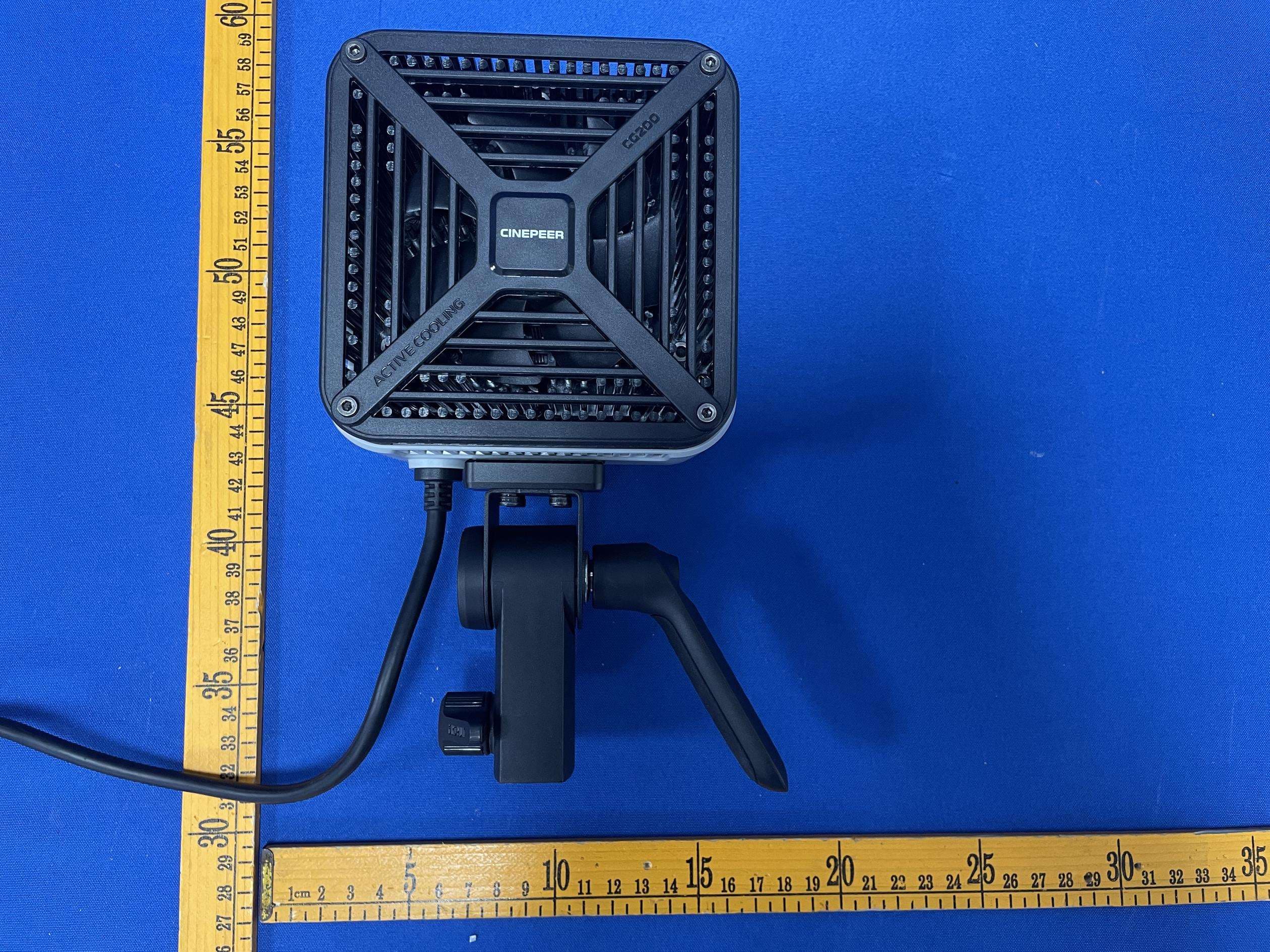
2AIHFZYPLG108
Aug 26, 2024ZHIYUN CINEPEER CG200 COB Light
Equipment Class
DTS - Digital Transmission System2AIHFZYEX1F06
Jul 08, 2024AI Tracker for SMOOTH Smartphone Stabilizer
Equipment Class
DTS - Digital Transmission System2AIHFZYPL113
Jun 25, 2024ZHIYUN CINEPEER C100 Multi Color Light
Equipment Class
DTS - Digital Transmission System2AIHFZYSM121
Jun 18, 2024ZHIYUN CINEPEER CQ5
Equipment Class
DTS - Digital Transmission System