2AIKSCXR-ITWCXR-I
Mares Spa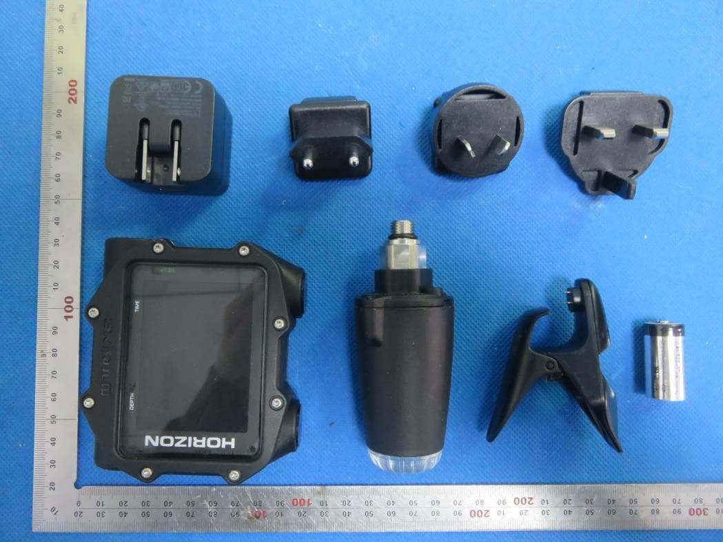
Click to zoom
Application Details
- Equipment Class
- DCD - Part 15 Low Power Transmitter Below 1705 kHz
- Date of Grant
- May 24, 2020
- Application Purpose
- Original Equipment
- Date of Application
- May 24, 2020
- Equipment Note
- CXR-I
- Frequency Range
- 0.04600000 - 0.04600000
- Company
- Mares Spa
- Country
- Italy
Documents & Files
Document Text
Text extracted from the exhibit documents filed with the FCC. Open a document above to read the original.
Users Manual
CXR-I Dive Computer • TABLE OF CONTENTS IMPORTANT WARNINGS DISCLAIMER PART I 3 3 4 4 4 5 5 5 5 5 6 6 6 6 7 7 7 7 PART II 11 11 11 11 11 11 11 11 12 12 12 12 12 12 12 13 13 14 14 14 14 • 8. DIVING WITH CXR-I 8.1. 8.2. 8.3. 8.4. 8.5. A FEW WORDS ABOUT NITROX ALTITUDE LOGBOOK DIVE PLANNER ALARMS 8.5.1. ASCENT RATE 8.5.2. MOD/ppO 2 8.5.3. CNS = 75% 8.5.4. MISSED DECOMPRESSION STOP 8.5.4.1. MISSED DECO STOP MODE 8.5.5. LOW TANK PRESSURE / RGT < 3 MIN 8.5.6. LOW BATTERY • 1. INTRODUCTION 1.1. 1.2. 1.3. 1.4. GLOSSARY OPERATING MODES TURNING ON CXR-I AND MAIN MENU RECHARGEABLE BATTERY 1.4.1. CHARGING THE BATTERY COMMUNICATING VIA USB CABLE OR BLUETOOTH BUTTON OPERATION IN CASE OF EMERGENCY (ICE) MOUNTING AND PAIRING OF THE TANK MODULE (OPTIONAL) TURNING OFF CXR-I 1.5. 1.6. 1.7. 1.8. 1.9. • 9. DISPLAY INFORMATION • 2. SET DIVE 9.1. 9.2. 9.3. 9.4. 9.5. 9.6. 9.7. DETAILED DESCRIPTION OF DISPLAYED DATA DEEP, DECO AND SAFETY STOPS FUTURE DECOMPRESSION DIVE PROFILE COMPASS TISSUE SATURATION GRAPH DECO SUMMARY TABLE (TO BE INTRODUCED VIA FREE FIRMWARE UPGRADE SOON) VIEWING MAPS DURING A DIVE UNDERWATER MENU 2.1. 2.2. MODE ALGORITHM 2.2.1. 2.2.2. MAIN GF ALTERNATE GF (TO BE INTRODUCED VIA FREE FIRMWARE UPGRADE SOON) PERSONALIZATION REPETITIVE DIVES MULTIDAY 7 8 8 8 8 8 9 9 9 2.2.3. 2.2.4. 2.2.5. 14 15 15 15 15 15 16 16 9.8. 9.9. 2.3. GAS INTEGRATION 2.3.1. COLOR CODING FOR PRESSURE RANGES WARNINGS 2.4.1. MAX DEPTH 2.4.2. DIVE TIME 2.4.3. NO STOP (TO BE INTRODUCED VIA FREE FIRMWARE UPGRADE SOON) 2.4.4. ENTERING DECO (TO BE INTRODUCED VIA FREE FIRMWARE UPGRADE SOON) 2.4.5. RGT (TO BE INTRODUCED VIA FREE FIRMWARE UPGRADE SOON) MULTIGAS 2.5.1. PREDICTIVE 2.5.2. ALLOW SWITCH BELOW MOD (TO BE INTRODUCED VIA FREE FIRMWARE UPGRADE SOON) FUTURE DECO WATER NIGHT MODE DEEP STOP DECO STOP (TO BE INTRODUCED VIA FREE FIRMWARE UPGRADE SOON) SECONDS (TO BE INTRODUCED VIA FREE FIRMWARE UPGRADE SOON) LINKED MAP ERASE DESATURATION ALL SILENT MODE ASCENT VIOLATION • 10. AFTER THE DIVE • 11. DIVING WITH MORE THAN ONE GAS MIXTURE 2.4. 11.1. 11.2. 11.3. SETTING MORE THAN ONE GAS SWITCHING GAS SPECIAL SITUATIONS 9 11.3.1. SWITCHING BACK TO A GAS MIXTURE WITH LOWER OXYGEN CONCENTRATION SUBMERGING BELOW THE MOD AFTER A GAS SWITCH RGT WHEN DIVING WITH MORE THAN ONE GAS MIXTURE LOGBOOK FOR DIVES WITH MORE THAN ONE GAS MIXTURE 9 16 16 11.3.2. 11.3.3. 9 9 9 2.5. 16 11.3.4. 16 9 9 9 9 9 11.4. DIVING WITH MORE THAN ONE GAS MIXTURE - TRIMIX OR HELIOX 2.6. 2.7. 2.8. 2.9. 2.10. (TO BE INTRODUCED VIA FREE FIRMWARE UPGRADE SOON) • 12. BOTTOM TIMER MODE 12.1. DIVE VIOLATION INDUCED BOTTOM TIMER MODE • 13. TAKING CARE OF CXR-I 16 16 16 17 17 17 18 18 18 13.1. 13.2. TECHNICAL INFORMATION MAINTENANCE 13.2.1. REPLACING THE BATTERY IN CXR-I 9 2.11. 9 9 9 9 9 10 • 14. WARRANTY 2.12. 2.13. 2.14. 2.15. 14.1. 14.2. WARRANTY EXCLUSIONS HOW TO FIND THE PRODUCT SERIAL NUMBER AND ELECTRONIC ID 18 18 20 • 15. DISPOSAL OF THE DEVICE FIGURE • 3. SET COMPUTER 3.1. 3.2. 3.3. 3.4. 3.5. 3.6. LANGUAGE UNITS CLOCK BRIGHTNESS COMPASS DECLINATION COMPASS CALIBRATION • 4. DIGITAL COMPASS 4.1. SETTING A BEARING INFO MAPS AND PHOTOS BUTTON LOCK • 5. • 6. • 7. 2 • IMPORTANT WARNINGS No part of this document may be reproduced, stored in a retrieval system, or transmitted in any form without the written permission of Mares S.p.A. Mares adopts a policy of continuing improvement, and therefore reserves the right to make changes and enhancements to any of the products described in this manual without notice. Under no circumstances shall Mares be held responsible for any loss or damage sustained by third parties deriving from the use of this instrument. DISCLAIMER This manual describes how to operate an instrument and it describes the information provided by the instrument during a dive. Neither this manual nor the instrument are a substitute for dive training, common sense and good diving practices. How the information provided by the instrument is interpreted and put to use by the diver is not the responsibility of Mares. Read the manual carefully and make sure you understand completely how the instrument works and the information it provides during a dive, including information on depth, time, decompression obligations and all warnings and alarms. Unless you fully understand how the instrument works and the information it displays and unless you accept full responsibility for using this instrument, do not dive with it. 3 WARNING The dive computer cannot ensure against possible decompression sickness. WARNING The dive computer must not be used in conditions that preclude its use (e.g.: low or no visibility, making it impossible to read the gauge). WARNING Do not dive if the display appears unusual or unclear. WARNING A dive computer is an electronic instrument and as such it is not immune to failure. To protect yourself against the unlikely event of a failure, in addition to the dive computer, also use a depth gauge, a submersible pressure gauge, a timer or watch, and dive tables. CXR-I Dive Computer • PART I • 1. INTRODUCTION 1.1. GLOSSARY AGF: Alternate gradient factor AIR: Air dive Total ascent time, the time it takes to perform the ascent from your current depth to the surface in a decompression dive, including all decompression stops and assuming an ascent rate of 10m/min or 33ft/min. ASC: ASC + X: The overall ascent time inclusive of all decompression stops if the dive is extended by X minutes at the current depth. AVG: Average depth, calculated from the beginning of the dive. CNS: Central Nervous System. CNS% is used to quantify toxic effects of oxygen. D-TIME: Dive time, the whole time spent below a depth of 1.2m/4ft. DESAT: Desaturation time. The time needed for the body to eliminate the nitrogen taken up during diving. Gas integration: The feature in CXR-I to include tank pressure information in its calculations and to display it on the computer screen. Gas switching: The act of changing from one breathing gas to another. GF: Gradient factor Gradient Factor: Per…
Text truncated - open the document above for the full version.
External Photos
External Photos ALL VIEW OF EUT TOP VIEW OF EUT BOTTOM VIEW OF EUT FRONT VIEW OF EUT BACK VIEW OF EUT LEFT VIEW OF EUT RIGHT VIEW OF EUT
ID Label/Location Info
FCC ID Label Location FCC ID: 2AIKSCXR-ITW This device complies with Part 15 of the FCC Rules. Operation is subject to the following two conditions: (1) this device may not cause harmful interference, and (2) this device must accept any interference received, including interference that may cause undesired operation.
Internal Photos
Internal Photos OPEN VIEW-1 OF EUT OPEN VIEW-2 OF EUT OPEN VIEW-3 OF EUT 46kHz Antenna INTERNAL VIEW-1 OF EUT INTERNAL VIEW-2 OF EUT embedded BLE antenna INTERNAL VIEW-3 OF EUT INTERNAL VIEW-4 OF EUT
Operational Description
MARES SPA Declaration concerning Antenna Specification It is hereby declared that the product Model No.: CXR-I FCC ID: 2AIKSCXR-ITW fulfills the requirement in FCC test relating to the antenna type. The device specified above confirms to the FCC recommendations for internal antenna type(s) described below: 1 Type of antenna: Integral Antenna Gain of the antenna: 0 dBi Frequency range: 46 kHz 2 Type of antenna: Integral Antenna Gain of the antenna: 0 dBi Frequency range: 2.402 GHz to 2.480GHz The mounting of the antenna is fixed to the radio module and no other antenna should be used. Company name: MARES SPA Address: SALITA BONSEN, 4 16035 RAPALLO (GE) ITALY Place: RAPALLO Date: 2020-05-21 Signature:
RF Exposure Info
RF EXPOSURE EVALUATION 1. PRODUCT INFORMATION Product Description CXR-I Model Name CXR-I FCC ID 2AIKSCXR-ITW 2. EVALUATION METHOD According to 447498 D01 General RF Exposure Guidance v05 The 1-g and 10-g SAR test exclusion thresholds for 100 MHz to 6 GHz at test separation distances ≤ 50 mm are determined by: [(max. power of channel, including tune-up tolerance, mW)/(min. test separation distance, mm)] ·[√f(GHz)] ≤ 3.0 for 1-g SAR and ≤ 7.5 for 10-g extremity SAR. Where f(GHz) is the RF channel transmit frequency in GHz Power and distance are rounded to the nearest mW and mm before calculation 3. CALCULATION BT Part: P t =0.843dBm=1.21mW The value of the Maximum output power P t is referred to the test report of the CFR47 §15.247. The result for RF exposure evaluation SAR=(1.21mW /5mm) .[√2.480(GHz)]= 0.38<3.0 for 1-g SAR and ≤ 7.5 for 10-g extremity SAR. 46kHz Part: P t =-27.63dBm=0.0017mW<1019mW The BT and 46kHz cannot transmitting simultaneously. 4. CONCLUSION The SAR evaluation is not required.
Test Report
Page 1 of 25 FCC Test Report Report No.: AGC09494191102FE03 FCC ID : 2AIKSCXR-ITW APPLICATION PURPOSE : Original Equipment PRODUCT DESIGNATION : CXR-I BRAND NAME : MARES MODEL NAME : CXR-I APPLICANT : MARES SPA DATE OF ISSUE : Dec. 20, 2019 STANDARD(S) TEST PROCEDURE(S) : FCC Part 15 Rules REPORT VERSION : V1.0 Attestation of Global Compliance (Shenzhen) Co., Ltd CAUTION: This report shall not be reproduced except in full without the written permission of the test laboratory and shall not be quoted out of context. Report No.: AGC09494191102FE03 Page 2 of 25 REPORT REVISE RECORD Report Version Revise Time Issued Date Valid Version Notes V1.0 / Dec. 20, 2019 Valid Initial Release Report No.: AGC09494191102FE03 Page 3 of 25 TABLE OF CONTENTS 1. VERIFICATION OF CONFORMITY ............................................................................................................... 4 2. GENERAL INFORMATION ............................................................................................................................ 5 2.1. PRODUCT DESCRIPTION ..................................................................................................................... 5 3. MEASUREMENT UNCERTAINTY ................................................................................................................. 6 4. DESCRIPTION OF TEST MODES ................................................................................................................. 7 5. SYSTEM TEST CONFIGURATION ............................................................................................................... 8 5.1. CONFIGURATION OF EUT SYSTEM ..................................................................................................... 8 5.2. EQUIPMENT USED IN EUT SYSTEM ..................................................................................................... 8 5.3. SUMMARY OF TEST RESULTS .............................................................................................................. 8 6. TEST FACILITY ............................................................................................................................................. 9 7. RADIATED EMISSION ................................................................................................................................. 10 7.1TEST LIMIT ............................................................................................................................................. 10 7.2. MEASUREMENT PROCEDURE ............................................................................................................ 11 7.3. TEST SETUP ......................................................................................................................................... 12 7.4. TEST RESULT ....................................................................................................................................... 13 8. 20DB BANDWIDTH ..................................................................................................................................... 16 8.1. MEASUREMENT PROCEDURE ........................................................................................................... 16 8.2. TEST SET-UP (BLOCK DIAGRAM OF CONFIGURATION) ................................................................... 16 8.3. MEASUREMENT RESULTS .................................................................................................................. 17 APPENDIX A: PHOTOGRAPHS OF TEST SETUP ........................................................................................ 18 APPENDIX B: PHOTOGRAPHS OF EUT ....................................................................................................... 19 Report No.: AGC09494191102FE03 Page 4 of 25 1. VERIFICATION OF CONFORMITY Applicant MARES SPA Address SALITA BONSEN, 4 16035 RAPALLO (GE) ITALY Manufacturer MARES SPA Address SALITA BONSEN, 4 16035 RAPALLO (GE) ITALY Factory MARES SPA Address SALITA BONSEN, 4 16035 RAPALLO (GE) ITALY Product Designation CXR-I Brand Name MARES Test Model CXR-I Date of test Nov. 15, 2019 to Dec. 18, 2019 Deviation No any deviation from the test method Condition of Test Sample Normal Test Result Pass Report Template AGCRT-US-BR/RF We hereby certify that: The above equipment was tested by Attestation of Global Compliance (Shenzhen) Co., Ltd. The test data, data evaluation, test procedures, and equipment configurations shown in this report were made in accordance with the procedures given in ANSI C63.10 (2013) and the energy emitted by the sample EUT tested as described in this report is in compliance with Section 15.207, 15.209, 15.203 of the FCC Part 15, Subpart C Rules. The results of testing in this report apply to the product/system which was tested only. Prepared By Nini Guo (Project Engineer) Dec. 20, 2019 Reviewed By Max Zhang (Reviewer) Dec. 20, 2019 Approved By Forrest Lei (Authorized Officer) Dec. 20, 2019 Report No.: AGC09494191102FE03 Page 5 of 25 2. GENERAL INFORMATION 2.1. PRODUCT DESCRIPTION A major technical description of EUT is described as following Operation Frequency 46 kHz Maximum field strength 67.57dBuV/m(PK)@3m Modulation OOK Number of channels 1 Antenna Gain 0dBi Antenna Designation Integral Antenna (Met 15.203 Antenna requirement) Hardware Version MARES20737S Software Version BLE 20737S ROM Power Supply DC 3.635V by battery Report No.: AGC09494191102FE03 Page 6 of 25 3. MEASUREMENT UNCERTAINTY The uncertainty is calculated using the methods suggested in the “Guide to the Expression of Uncertainty in measurement” (GUM) published by CISPR and ANSI. - Uncertainty of Conducted Emission, Uc = ±3.2 dB - Uncertainty of Radiated Emission below 1GHz, Uc = ±3.9 dB - Uncertainty of Radiated Emission above 1GHz, Uc = ±4.8 dB Report No.: AGC09494191102FE03 Page 7 of 25 4. DESCRIPTION OF TEST MODES NO. TEST MODE DESCRIPTION 1 46KHz transmitting mode Note: 1. The mode 1 was the worst…
Text truncated - open the document above for the full version.
Test Setup Photos
Test Setup Photos FCC RADIATED EMISSION TEST SETUP BELOW 1GHZ
Contact Information
Applicant
Giovanni Distefano(Technical Director)
Test Firm
Attestation of Global Compliance (Shenzhen) Co., LDoris Li
[email protected]+86-755-25234088
Technical Specifications
| # | Rule Parts | Frequency Range | Power Output |
|---|---|---|---|
| 1 | 15C | 0.046 MHz - 0.046 MHz | 1.22 mW |
Other Applications from Mares Spa

2AIKSPUCK4
Oct 24, 2023PUCK 4
Equipment Class
DTS - Digital Transmission System