2AILBDIGINET-MTmono transmitter
ENPING ENBAO ELECTRONIC CO., LTD.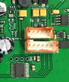
Click to zoom
Application Details
- Equipment Class
- DXX - Part 15 Low Power Communication Device Transmitter
- Date of Grant
- Oct 13, 2020
- Application Purpose
- Original Equipment
- Date of Application
- Oct 13, 2020
- Equipment Note
- mono transmitter
- Frequency Range
- 903.40000000 - 927.70000000
- Country
- China
Documents & Files
Document Text
Text extracted from the exhibit documents filed with the FCC. Open a document above to read the original.
Users Manual
owner's manual DigiNet Professional Wireless Audio System for Active Loudspeakers Table of Contents FCC Information ...................................................... 4 Safety Instructions ................................................... 5 Welcome ............................................................... 6 Listening for a Lifetime ............................................. 7 Getting Started ....................................................... 8 Quick Start Guide .................................................... 9 Getting Connected ................................................. 11 Descriptions and Functions ..................................... 13 Battery Replacement ............................................. 16 Troubleshoot ........................................................ 17 4 1. IMPORTANT NOTICE: DO NOT MODIFY THIS UNIT!: This product, when installed as indicated in the instructions contained in this manual, meets FCC requirements. Modifications not expressly approved by Vocopro may void your authority, granted by the FCC, to use this product. 2. IMPORTANT: When connecting this product to accessories and/or another product use only high quality shielded cables. Cable(s) supplied with this product MUST be used. Follow all installation instructions. Failure to follow instructions could void your FCC authorization to use this product in the U.S.A. 3. NOTE: This product has been tested and found to comply with the requirements listed in FCC Regulations, Part 15 for Class "B" digital devices. Compliance with these requirements provides a reasonable level of assurances that your use of this product in a residential environment will not result in harmful interference with other electronic devices. This equipment generates/uses radio frequencies and, if not installed and used according to the instructions found in the owner's manual, may cause interference harmful to the operation of other electronic devices. Compliance with FCC regulations does not guarantee that interference will not occur in all installations. If this product is found to be the source of interference, which can be determined by turning the unit "Off" and "On", please try to eliminate the problem by using one of the following measures: Relocate either this product or the device that is being affected by the interference. Use power outlets that are on different branch (circuit breaker or fuse) circuits or install AC line filter(s). In the case of radio or TV interference, relocate/reorient the antenna. If the antenna lead-in is 300-ohm ribbon lead, change the lead-in to coaxial type cable. If these corrective measures do not produce satisfactory results, please contact your local retailer authorized to distribute Vocopro products. If you can not locate the appropriate retailer, please contact Vocopro, 1728 Curtiss Court, La Verne, CA 91750. 1. To ensure the finest performance, please read this manual carefully. Keep it in a safe place for future reference. 2. Install your unit in a cool, dry, clean place - away from windows, heat sources, and too much vibration, dust, moisture or cold. Avoid sources of hum (transformers, v motors). To prevent fire or electrical shock, do not expose to rain and water. 3. Do not operate the unit upside-down. 4. Never open the cabinet. If a foreign object drops into the set, contact your dealer. 5. Place the unit in a location with adequate air circulation. Do not interfere with its proper ventilation; this will cause the internal temperature to rise and may result in a failure. 6. Do not use force on switches, knobs or cords. When moving the unit, first turn the unit off. Then gently disconnect the power plug and the cords connecting to other equipment. Never pull the cord itself. 7. Do not attempt to clean the unit with chemical solvents: this might damage the finish. Use a clean, dry cloth. 8. Be sure to read the "Troubleshooting" section on common operating errors before concluding that your unit is faulty. 9. This unit consumes a fair amount of power even when the power switch is turned off. We recommend that you unplug the power cord from the wall outlet if the unit is not going to be used for a long time. This will save electricity and help prevent fire hazards. To disconnect the cord, pull it out by grasping the plug. Never pull the cord itself. 10. To prevent lightning damage, pull out the power cord and remove the antenna cable during an electrical storm. 11. The general digital signals may interfere with other equipment such as tuners or receivers. Move the system farther away from such equipment if interference is observed. NOTE: Please check the copyright laws in your country before recording from records, compact discs, radio, etc. Recording of copyrighted material may infringe copyright laws. CAUTION The apparatus is not disconnected from the AC power source so long as it is connected to the wall outlet, even if the apparatus itself is turned off. To fully ensure that the apparatus is indeed fully void of residual power, leave unit disconnected from the AC outlet for at least fifteen seconds. CAUTION: READ THIS BEFORE OPERATING YOUR UNIT Voltage Selector (General Model Only) Be sure to position the voltage selector to match the voltage of your local power lines before installing the unit. 110V FCC Information 5 Safety Instructions CAUTION RISK OF SHOCK CAUTION: To reduce the risk of electric shock, do not remove cover (or back). No user-serviceable parts inside. Only refer servicing to qualified service personnel. WARNING To reduce the risk of fire or electric shock, do not expose this unit to rain or moisture. Explanation of Graphical Symbols The lightning flash & arrowhead symbol, within an equilateral triangle, is intended to alert you to the presence of danger. The exclamation point within an equilateral triangle is intended to alert you to the presence of important operating and servicing instructions. 1. Read Instructions - All the safety a…
Text truncated - open the document above for the full version.
External Photos
Reference N Waltek Tes http://www EXHIBI EUT View 1 EUT View 2 No.: STR181 sting Group w.semtest.co T 2 - EUT 1 2 128308I (Shenzhen) m.cn T EXTER Co., Ltd. RNAL PH HOTOGR APHS Reference N Waltek Tes http://www EUT View 3 EUT View 4 No.: STR181 sting Group w.semtest.co 3 4 128308I (Shenzhen) m.cn Co., Ltd. Reference N Waltek Tes http://www EUT View 5 EUT View 6 No.: STR181 sting Group w.semtest.co 5 6 128308I (Shenzhen) m.cn Co., Ltd. Reference N Waltek Tes http://www EUT View 7 No.: STR181 sting Group w.semtest.co 7 128308I (Shenzhen) m.cn Co., Ltd.
ID Label/Location Info
Reference N Waltek Tes http://www EXHIBI Proposed Specificatio n it is visible durable to r expected lif e Proposed No.: STR181 sting Group w.semtest.co T 1 - PRO FCC ID La ns: The label or easily acc emain fully l etime. Label Loca 128308I (Shenzhen) m.cn ODUCT L abel Forma FCC ID: 2 This device Operation i (1) This de (2) this dev including operation. shall be secu cessible to th legible and in ation on EU Co., Ltd. LABELIN at AILBDIGI e complies is subject to vice may no vice must interferenc urely affixed t he user, and ntact on the UT FCC NG INET-MT with Part o the followi ot cause ha accept any ce that m to a permane shall not be device in al l ID Label Lo 15 of the F ing two con armful interf interferenc may cause ently attached readily detac l normal cond cation FCC Rules nditions: ference, and ce received undesired d part of the d chable. The l ditions of use s. d d, d device, in a lo label shall be e throughout ocation where e sufficiently t the device’s e y s
Internal Photos
Reference N Waltek Tes http://www EXHIBI EUT Housi n EUT Housi n No.: STR181 sting Group w.semtest.co T 3 - EUT ng and Boar ng and Boar 128308I (Shenzhen) m.cn T INTER rd View 1 rd View 2 Co., Ltd. NAL PHO OTOGRA APHS Reference N Waltek Tes http://www Solder Boa r Solder Boa r No.: STR181 sting Group w.semtest.co rd-Compone rd-Compone 128308I (Shenzhen) m.cn ent View 1 ent View 2 Co., Ltd. Reference N Waltek Tes http://www Solder Boa r Solder Boa r No.: STR181 sting Group w.semtest.co rd-Compone rd-Compone 128308I (Shenzhen) m.cn ent View 3 ent View 4 Co., Ltd. Reference N Waltek Tes http://www Solder Boa r Solder Boa r No.: STR181 sting Group w.semtest.co rd-Compone rd-Compone 128308I (Shenzhen) m.cn ent View 5 ent View 5 Co., Ltd. Reference N Waltek Tes http://www Antenna V i No.: STR181 sting Group w.semtest.co iew Antenna 128308I (Shenzhen) m.cn Co., Ltd.
Test Report
Waltek Testing Group (Shenzhen) Co., Ltd. http://www.semtest.com.cn Page 1 of 30 TEST REPORT Reference No. .................... : STR18128308I FCC ID ................................ : 2AILBDIGINET-MT Applicant ........................... : ENPING ENBAO ELECTRONIC CO., LTD. Address ............................. : B3, 3 Zone, Enping Park, Industrial Transfer Park of Jiangmen, Guangdong, China Product Name ................... : mono transmitter Test Model. ........................ : DigiNet-MT Standards .......................... : FCC Part 15.249 Date of Receipt sample .... : Aug.28, 2020 Date of Test........................ : Aug.28, 2020 to Aug.31, 2020 Date of Issue ..................... : Aug.31, 2020 Test Result ......................... : Pass Remarks: The results shown in this test report refer only to the sample(s) tested, this test report cannot be reproduced, except in full, without prior written permission of the company. The report would be invalid without specific stamp of test institute and the signatures of compiler and approver. Prepared By: Waltek Testing Group (Shenzhen) Co., Ltd. Address: 1/F., Room 101, Building 1, Hongwei Industrial Park, Liuxian 2nd Road, Block 70 Bao'an District, Shenzhen, Guangdong, China Tel.: +86-755-33663308 Fax.: +86-755-33663309 Tested by: Reviewed By: Approved & Authorized By: Tested by: Lion Cai / RF Manager Silin Chen / Manager Reference No.: STR18128308I Page 2 of 30 Waltek Testing Group (Shenzhen) Co., Ltd. http://www.semtest.com.cn TABLE OF CONTENTS 1. GENERAL INFORMATION ................................................................................................................................... 4 1.1 PRODUCT DESCRIPTION FOR EQUIPMENT UNDER TEST (EUT) ............................................................................... 4 1.2 TEST STANDARDS ................................................................................................................................................... 6 1.3 TEST METHODOLOGY ............................................................................................................................................. 6 1.4 TEST FACILITY ....................................................................................................................................................... 6 1.5 EUT SETUP AND TEST MODE ................................................................................................................................. 7 1.6 MEASUREMENT UNCERTAINTY .............................................................................................................................. 7 1.7 TEST EQUIPMENT LIST AND DETAILS ..................................................................................................................... 8 2. SUMMARY OF TEST RESULTS ......................................................................................................................... 10 3. ANTENNA REQUIREMENTS .............................................................................................................................. 11 3.1 STANDARD APPLICABLE ....................................................................................................................................... 11 3.2 TEST RESULT........................................................................................................................................................ 11 4. RADIATED EMISSIONS ....................................................................................................................................... 12 4.1 STANDARD APPLICABLE ....................................................................................................................................... 12 4.2 TEST PROCEDURE ................................................................................................................................................. 12 4.3 CORRECTED AMPLITUDE & MARGIN CALCULATION ............................................................................................ 14 4.4 SUMMARY OF TEST RESULTS/PLOTS .................................................................................................................... 14 5. OUT OF BAND EMISSIONS ................................................................................................................................. 23 5.1 STANDARD APPLICABLE ....................................................................................................................................... 23 5.2 TEST PROCEDURE ................................................................................................................................................. 23 5.3 SUMMARY OF TEST RESULTS/PLOTS .................................................................................................................... 23 6. EMISSION BANDWIDTH ..................................................................................................................................... 26 6.1 STANDARD APPLICABLE ....................................................................................................................................... 26 6.2 TEST PROCEDURE ................................................................................................................................................. 26 6.3 SUMMARY OF TEST RESULTS/PLOTS .................................................................................................................... 26 7. CONDUCTED EMISSIONS .................................................................................................................................. 28 7.1 TEST PROCEDURE ................................................................................................................................................. 28 7.2 BASIC TEST SETUP BLOCK DIAGRAM ................................................................................................................... 28 7.3 TEST …
Text truncated - open the document above for the full version.
Test Setup Photos
Reference N Waltek Tes http://www EXHIBI Conducted Radiation E No.: STR181 sting Group w.semtest.co T 4 - TES Emission Te Emission Tes 128308I (Shenzhen) m.cn ST SETUP est Setup st Setup (Belo Co., Ltd. P PHOTO ow 30MHz) OGRAPH HS Reference N Waltek Tes http://www Radiation E Radiation E No.: STR181 sting Group w.semtest.co Emission Tes Emission Tes 128308I (Shenzhen) m.cn st Setup (30M st Setup (Abo Co., Ltd. MHz to 1GHz ove 1GHz) z) Reference N Waltek Tes http://www No.: STR181 sting Group w.semtest.co 128308I (Shenzhen) m.cn Co., Ltd.
Contact Information
Applicant
Yuki Feng(sales manager)
Test Firm
Waltek Testing Group (Shenzhen) Co., Ltd.Jandy So
Technical Specifications
| # | Rule Parts | Frequency Range | Power Output |
|---|---|---|---|
| 1 | 15C | 903.4 MHz - 927.7 MHz | - |