2AJ4H-T816TPMS Sensor
I YUAN PRECISION INDUSTRIAL CO., LTD.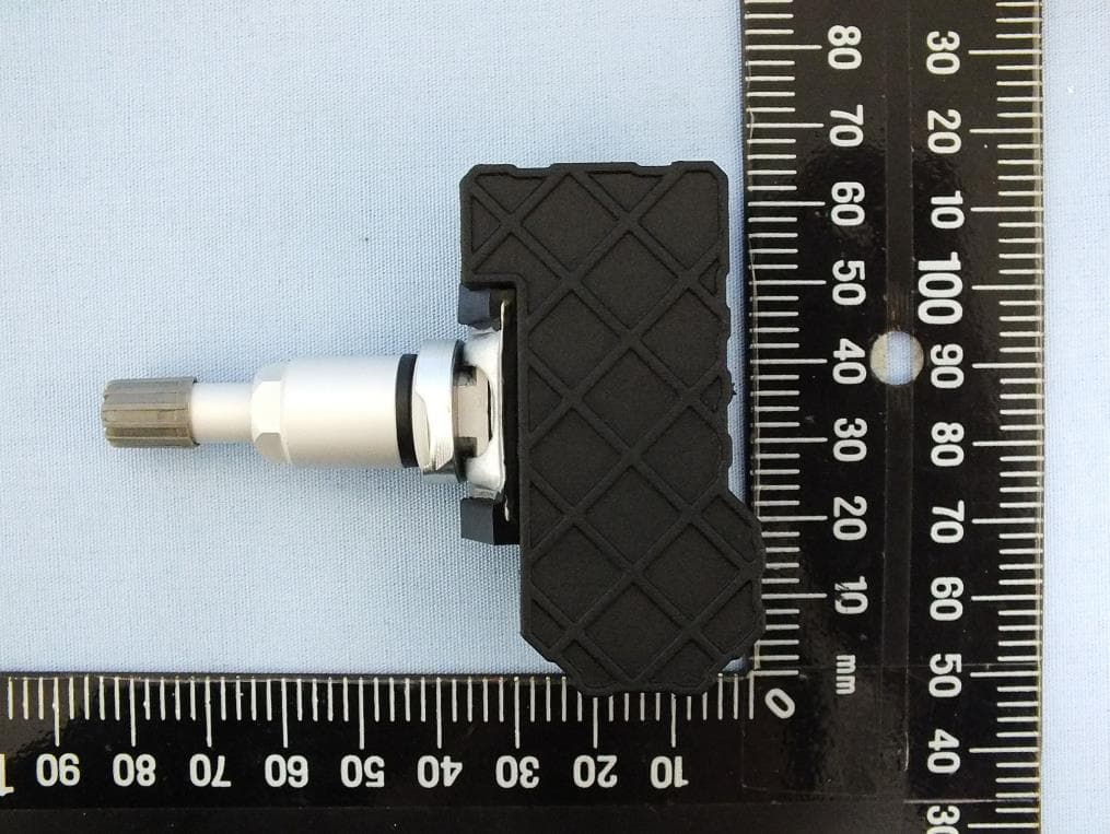
Click to zoom
Application Details
- Equipment Class
- DSC - Part 15 Security/Remote Control Transmitter
- Date of Grant
- May 03, 2020
- Application Purpose
- Original Equipment
- Date of Application
- Apr 29, 2020
- Equipment Note
- TPMS Sensor
- Frequency Range
- 433.00000000 - 433.00000000
- Country
- Taiwan
Documents & Files
Document Text
Text extracted from the exhibit documents filed with the FCC. Open a document above to read the original.
Users Manual
Installation Guides TIY-81006 2in 1 (315MHz+433MHz) Federal Communication Commission Interference Statement This equipment has been tested and found to comply with the limits for a Class B digital device, pursuant to Part 15 of the FCC Rules. These limits are designed to provide reasonable protection against harmful interference in a residential installation. This equipment Installation of TYC TPMS Sensor with metal valves 1. Use TOOL『PROGRAM SENSOR 』to program TYC TPMS sensor. 2. Remove any corrosion or dirt on valve stem hole in rim. Ensure there is a clean smooth surface for the fitting of TYC sensor, sensor valve stem, and sensor nut to the rim 3. Remove TYC sensor nut. 4. Press TYC sensor body onto the inner rim, and use the torque wrench to tighten the TYC sensor. 5. Inflate the tire to proper tire pressure, proper tire pressure usually show in the bottom of inner door. 6. Use TOOL 『CHECK SENSOR 』to check if tire pressure proper. 7. The housing must not have any contact with the rim; this ensures the proper mounting of the sensor and valve. 8. When mounting the tire, be aware the sensor must not be pinched between the bead and the rim; ensure the tire bead lubricant does not cover the sensor’s pressure port. Then inflate tire until both beads are securely in place and to recommended pressure. 9. TYC sensors must be with TYC sensor accessories and must be configured with an appropriate TPMS programming tool before use. Without configuration, the TYC sensor will not be activated. 10. Conduct the specified relearn procedure according to the instructions manual of the vehicle or the TPMS diagnostic tool. Possible relearn procedures: -Automatic relearn -Manual relearn -Relearn via OBDII interface generates, uses and can radiate radio frequency energy and, if not installed and used in accordance with the instructions, may cause harmful interference to radio communications. However, there is no guarantee that interference will not occur in a particular installation. If this equipment does cause harmful interference to radio or television reception, which can be determined by turning the equipment off and on, the user is encouraged to try to correct the interference by one of the following measures: - Reorient or relocate the receiving antenna. - Increase the separation between the equipment and receiver. - Connect the equipment into an outlet on a circuit different from that to which the receiver is connected. - Consult the dealer or an experienced radio/TV technician for help. FCC Caution: Any changes or modifications not expressly approved by the party responsible for compliance could void the user's authority to operate this equipment. This device complies with Part 15 of the FCC Rules. Operation is subject to the following two conditions: (1) This device may not cause harmful interference, and (2) this device must accept any interference received, including interference that may cause undesired operation.
External Photos
Project No.: 9O3002 Page No. : 1 of 7 Photographs of EUT Project No.: 9O3002 Page No. : 2 of 7 Project No.: 9O3002 Page No. : 3 of 7
ID Label/Location Info
FCC ID: 2AJ4H-T816
Internal Photos
Project No.: 9O3002 Page No. : 4 of 7 Project No.: 9O3002 Page No. : 5 of 7 Project No.: 9O3002 Page No. : 6 of 7 Project No.: 9O3002 Page No. : 7 of 7
Test Report
Report No.: FR9O3002 Page : 1 of 59 Report Version: Rev. 01 FCC Test Report FCC ID : 2AJ4H-T816 Equipment : TPMS Sensor Model No. : TIY-081006 Brand Name : TYC-TIY Applicant : I YUAN PRECISION INDUSTRIAL CO., LTD. Address : NO.24, Dinghu Rd., Guishan Dist., Taoyuan City 33378, Taiwa(R.O.C.) Standard : 47 CFR FCC Part 15.231 Received Date : Oct. 30, 2019 Tested Date : Nov. 22 ~ Nov. 26, 2019 We, International Certification Corp., would like to declare that the tested sample has been evaluated and in compliance with the requirement of the above standards. The test results contained in this report refer exclusively to the product. It may be duplicated completely for legal use with the approval of the applicant. It shall not be reproduced except in full without the written approval of our laboratory. Reviewed by: Approved by: Along Chen / Assistant Manager Gary Chang / Manager Report No.: FR9O3002 Page : 2 of 59 Report Version: Rev. 01 Table of Contents 1 GENERAL DESCRIPTION .................................................................................................................... 5 1.1 Information .............................................................................................................................................. 5 1.2 Local Support Equipment List ................................................................................................................ 6 1.3 Test Setup Chart .................................................................................................................................... 6 1.4 The Equipment List ................................................................................................................................ 7 1.5 Test Standards ....................................................................................................................................... 8 1.6 Deviation from Test Standard and Measurement Procedure ................................................................. 8 1.7 Measurement Uncertainty ...................................................................................................................... 8 2 TEST CONFIGURATION ....................................................................................................................... 9 2.1 Testing Condition ................................................................................................................................... 9 2.2 The Worst Test Modes and Channel Details ......................................................................................... 9 3 TRANSMITTER TEST RESULTS ........................................................................................................ 10 3.1 Radiated Emission ............................................................................................................................... 10 3.2 Transmission and Deactivation Time ................................................................................................... 41 3.3 20dB and Occupied Bandwidth ............................................................................................................ 54 4 TEST LABORATORY INFORMATION ............................................................................................... 59 Report No.: FR9O3002 Page : 3 of 59 Report Version: Rev. 01 Release Record Report No. Version Description Issued Date FR9O3002 Rev. 01 Initial issue Apr. 29, 2020 Report No.: FR9O3002 Page : 4 of 59 Report Version: Rev. 01 Summary of Test Results FCC Rules Test Items Measured Result 15.207 AC Power Line Conducted Emissions Note 1 N/A 15.231(b) Field Strength of Fundamental emissions Meet the requirement of limit Pass 15.231(b) 15.209 Unwanted Emissions Meet the requirement of limit Pass 15.231(a) Transmission and Deactivation Time Meet the requirement of limit Pass 15.231(c) 20dB bandwidth Meet the requirement of limit Pass 15.203 Antenna Requirement Meet the requirement of limit Pass N/A means Not Applicable. Note 1 : The EUT consumes DC power from battery, so the test is not required. Declaration of Conformity: The test results with all measurement uncertainty excluded are presented in accordance with the regulation limits or requirements declared by manufacturers. Comments and Explanations: The declared of product specification for EUT presented in the report are provided by the manufacturer, and the manufacturer takes all the responsibilities for the accuracy of product specification. Report No.: FR9O3002 Page : 5 of 59 Report Version: Rev. 01 1 General Description 1.1 Information 1.1.1 Specification of the Equipment under Test (EUT) RF General Information Frequency Range (MHz) Modulation Ch. Freq. (MHz) Channel Number Channel Bandwidth (kHz) 315 ASK 315 1 --- 315 FSK 315 1 --- 433 ASK 433 1 --- 433 FSK 433 1 --- Note: The device supports below 3 modes: 1) Rotating mode 2) Stationary mode 3) Alert mode 1.1.2 Antenna Details Ant. No. Type Gain (dBi) Connector 1 Monopole --- --- 1.1.3 EUT Operational Condition Power Supply Type 3Vdc from battery 1.1.4 Accessories Accessories No. Equipment Description 1 Battery Brand: maxell Model: CR2450W Power Rating: 3Vdc Report No.: FR9O3002 Page : 6 of 59 Report Version: Rev. 01 1.2 Local Support Equipment List Support Equipment List No. Equipment Brand Model FCC ID Remarks 1 315MHz controller --- TIY tool --- provided by applicant 1.3 Test Setup Chart Test Setup Diagram Report No.: FR9O3002 Page : 7 of 59 Report Version: Rev. 01 1.4 The Equipment List Test Item Radiated Emission Test Site 966 chamber1 / (03CH01-WS) Instrument Manufacturer Model No. Serial No. Calibration Date Calibration Until Spectrum Analyzer R&S FSV40 101498 Dec. 27, 2018 Dec. 26, 2019 Receiver R&S ESR3 101658 Dec. 11, 2018 Dec. 10, 2019 Bilog Antenna SCHWARZBECK VULB9168 VULB9168-522 Jul. 12, 2019 Jul. 11, 2020 Horn Antenna 1G-18G SCHWARZBECK BBHA 9120 D BBHA 9120 D 1096 Dec. 18, 2018 Dec. 17, 2019 Horn Antenna 18G-40G SCHWARZBECK BBHA 9170 BBHA…
Text truncated - open the document above for the full version.
Test Setup Photos
Report No.: FR9O3002 Page: : 1 of 4 Report Version: Rev. 01 Photographs of the Test Configuration Radiated Emission Below 1GHz Test Report No.: FR9O3002 Page: : 2 of 4 Report Version: Rev. 01 Radiated Emission Below 1GHz Test Report No.: FR9O3002 Page: : 3 of 4 Report Version: Rev. 01 Radiated Emission Above 1GHz Test Report No.: FR9O3002 Page: : 4 of 4 Report Version: Rev. 01 Radiated Emission Above 1GHz Test
Contact Information
Applicant
Yao John Shea(Electronic Dept. Manager)
Technical Contact
International Certification Corp.Gary Chang
[email protected]886-3-271-8628
No.3-1, Lane 6, Wen San 3rd St. Kwei Shan Dist., · Taiwan
Non-Technical Contact
International Certification Corp.Wendy Liao
[email protected]886-3-271-8629
Test Firm
International Certification Corp.Fu-Cheng Chuang
Technical Specifications
| # | Rule Parts | Frequency Range | Power Output |
|---|---|---|---|
| 2 | 15.231 | 433 MHz - 433 MHz | - |