2AJ4J-DISPENSER901Ticket dispenser
ddm hopt & schuler GmbH & Co. KG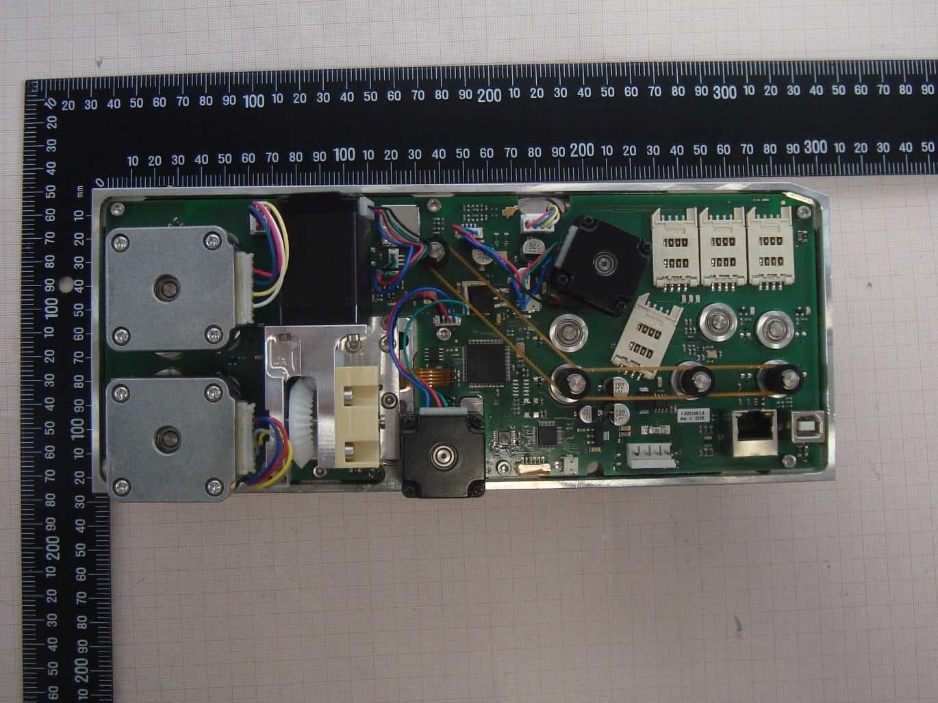
Click to zoom
Application Details
- Equipment Class
- DXT - Part 15 Low Power Transceiver, Rx Verified
- Date of Grant
- Nov 25, 2020
- Application Purpose
- Original Equipment
- Date of Application
- Nov 25, 2020
- Equipment Note
- Ticket dispenser
- Frequency Range
- 13.56000000 - 13.56000000
- Country
- Germany
Documents & Files
Document Text
Text extracted from the exhibit documents filed with the FCC. Open a document above to read the original.
Users Manual
die zeichen lesen die zeichen setzen reading the signssetting the signs RFID-Ticket-Ausgabe-Einheit 901-10110010000 RFID ticket dispenser 901-10110010000 D-78628 Rottweil Königsbergerstr. 12 Tel. (++49) 7 41 / 26 07-0 Fax (++49) 7 41 / 1 33 98 [email protected] www.hopt-schuler.com FCC ID Number: 2AJ4J-DISPENSER901 Rev. 1.01 2020.07.08 0.0 Inhaltsverzeichnis 1.0 Allgemeine Produktbeschreibung 2.0 Mechanische Kennwerte 3.0 Elektrische Kennwerte 4.0 Umgebungsbedingungen 5.0 Ticketspezifikation table of contents global product description mechanical characteristics electrical characteristics environmental conditions ticket specification 2.1 Lebensdauer 2.2 Einbaumaße / Abmessungen 2.3 Befestigung life dimensions fixation 3.1 Anschlusstechnik connection technique 4.1 Klimatische Bedingungen climatic conditions 5.1 Ticket ticket Beschreibung der Änderung Rev. Datum Rev. 01 08.07.2020 Rev. 01 08.07.2020 Rev. 01 08.07.2020 Rev. 01 08.07.2020 Rev. 0 Rev. 01 08.07.2020 Kapitel 1.1 FCC Hinweise FCC note Blatt.-Nr.: RFID-Ticket-Ausgabe-Einheit| 901-10110010000 | 2 RFID ticket dispenser / manual 901-10110010000-MNL.idw Blatt.-Nr.: RFID-Ticket-Ausgabe-Einheit| 901-10110010000 | 3 RFID ticket dispenser / manual 901-10110010000-MNL.idw Kapitel Beschreibung der Änderung Datum Rev. Rev. 0 Rev. 0 Rev. 0 6.0 Reinigung cleaning 7.0 Wartung service 7.1 Werkzeug und Hilfsmittel 7.2 Wartung Level 1 (mit geringem Aufwand - vor Ort) 7.3 Wartung Level 2 (mit mässigem Aufwand) 7.4 Wartung Level 3 (mit erhöhtem Aufwand - in der Werkstatt) tools and supports maintenance level 1 (with little effort - on site) maintenance level 2 (with moderate effort) maintenance level 3 (with elevated effort - in the workshop) 8.0 Ersatzteileliste spare part list The contents of this document are subject to revision without notice due to continued progress in methodology, design and manufacturing. No part of this document may be reproduced or transmitted in any form or by any means, for any purpose, without the prio written permission of "ddm hopt+schuler". ddm hopt+schuler shall have no liability for any errors or damages of any kind resulting from the use of this document. 9.0 Verschleißteile wear parts Rev. 0 Rev. 0 history Revision Datum / date Bermerkung / comment 00 2020.04.09 initial release 1.01 2020.07.08 Ergänzungen an Kapitel 1, 2, 3, 5. Kapitel 10 entfällt 1.0 Allgemeine Produktbeschreibung global product description Die RFID-Ticket-Ausgabe-Einheit besteht aus: • Papiereinzug • Schermodul • RFID Antenne • Thermodrucker Die Ticket-Ausgabe-Einheit 901-10110010000 ist eine hoch zuverlässige Einheit um vorperforierte Tickets aus bis zu 2 Boxen zu separieren, Kontaktlos-Tickets zu bearbeiten, mittels Thermodrucker von oben zu bedrucken und an den Kunden auszugeben. Das Separieren geschieht über ein Schermodul. Das Ticket kann ebenfalls von außen eingegebn werden um es zu bedrucken, mit der RFID Antenne zu bearbeiten und wieder auszugeben oder unter der Einheit abzulegen. Das Produkt 901-10110010000 von ddm hopt+schuler, ist eine RFID Ticket-Ausgabe-Einheit für den Einsatz bei: Ticket-Ausgabe-Systemen. The ticket dispenser consists of: • feeder • shearing module • RFID antenna • thermal printer The Ticket-Dispenser 901-10110010000 is a high reliable unit for seperating tickets from up to two paper boxes, process contactless tickets, print the ticket with a thermal printer from the top and issue it to the customer. Seperating is done by a shearing module. The ticket can also be accepted from the front to print it to handle the contactless chip and to give it back or capture it under the unit. The product 901-10110010000 developed by ddm hopt+schuler, is a dispenser for using in: ticket issue systems Blatt.-Nr.: RFID-Ticket-Ausgabe-Einheit| 901-10110010000 | 4 RFID ticket dispenser / manual 901-10110010000-MNL.idw Blatt.-Nr.: RFID-Ticket-Ausgabe-Einheit| 901-10110010000 | 5 RFID ticket dispenser / manual 901-10110010000-MNL.idw 1.1 FCC Hinweis FCC note Dieses Gerät entspricht Teil 15 der FCC-Standards. Der Betrieb unterliegt den folgenden zwei Bedingungen: (1) Dieses Gerät darf keine schädlichen Interferenzen verursachen, und (2) dieses Gerät muss alle empfangenen Interferenzen akzeptieren, einschließlich Interferenzen, die einen unerwünschten Betrieb verursachen können. Dieses Gerät wurde getestet und entspricht den Grenzwerten für digitale Geräte der Klasse B gemäß Teil 15 der FCC-Bestimmungen. Diese Grenzwerte sollen einen angemessenen Schutz gegen schädliche Interferenzen in Wohngebieten bieten. Dieses Gerät erzeugt, verwendet und strahlt möglicherweise Hochfrequenzenergie aus und kann, wenn es nicht in Übereinstimmung mit den Anweisungen installiert und verwendet wird, Funkstörungen verursachen. Es kann jedoch nicht garantiert werden, dass bei einer bestimmten Installation keine Interferenzen auftreten. Wenn dieses Gerät den Radio- oder Fernsehempfang stört, was durch Aus- und Einschalten des Geräts festgestellt werden kann, sollte der Benutzer versuchen, die Störung durch eine oder mehrere der folgenden Maßnahmen zu beheben: • Richten Sie die Empfangsantenne neu aus oder positionieren Sie sie neu. • Vergrößern Sie den Abstand zwischen Gerät und Empfänger. • Schließen Sie das Gerät an eine Steckdose an, die sich von dem Stromkreis unterscheidet, an den der Empfänger angeschlossen ist. • Wenden Sie sich an den Händler oder einen erfahrenen Radio- / Fernsehtechniker. This device complies with Part 15 of the FCC standard(s). Operation is subject to the following two conditions: (1) this device may not cause harmful interference, and (2) this device must accept any interference received, including interference that may cause undesired operation. This equipment has been tested and found to comply with the limits for a Class B digital device, pursuant to Part 15 of the FCC Rules. These limits are designed to provide reasonable protection against harmful interference in a residential installation. This equipment generates, uses…
Text truncated - open the document above for the full version.
External Photos
Annex A 1-8014/19-02-01_AnnexA External photos of the Equipment Under Test This addendum is electronically signed and valid without handwritten signature. For verification of the electronic signatures, the public keys can be requested at the testing laboratory. Document authorized: Hans Joachim Wolsdorfer Testing Manager Radio Communications & EMC CTC advanced GmbHUntertuerkheimer Str. 6-10 66117 Saarbruecken / Germany Phone: +49 681 5 98 - 0 Fax: +49 681 5 98 - 9075 web: ctcadvanced.com e-mail: [email protected] Photos Photo 1 Photo 2 2020-11-13Document No. 1-8014/19-02-01_AnnexA2/6 Photo 3 Photo 4 2020-11-13Document No. 1-8014/19-02-01_AnnexA3/6 Photo 5 Photo 6 2020-11-13Document No. 1-8014/19-02-01_AnnexA4/6 Photo 7 2020-11-13Document No. 1-8014/19-02-01_AnnexA5/6 Document history VersionApplied changesDate of release initial release2020-11-13 - END OF DOCUMENT - 2020-11-13Document No. 1-8014/19-02-01_AnnexA6/6
ID Label/Location Info
ID Label für RFID Ticket Dispenser 901 FCC ID: 2AJ4J-DISPENSER901
Internal Photos
Leiterplatten für RFID Ticket Dispenser 901 FCC ID: 2AJ4J-DISPENSER901
Test Report
TEST REPORT Test report no.: 1-8014/19-02-0 2 Testing laboratory Applicant CTC advanced GmbH Untertuerkheimer Strasse 6 – 10 66117 Saarbruecken / Germany Phone: + 49 681 5 98 - 0 Fax: + 49 681 5 98 - 9075 Internet: https://www.ctcadvanced.com e-mail: [email protected] Accredited Testing Laboratory: The testing laboratory (area of testing) is accredited according to DIN EN ISO/IEC 17025 (2018-03) by the Deutsche Akkreditierungsstelle GmbH (DAkkS) The accreditation is valid for the scope of testing procedures as stated in the accreditation certificate starting with the registration number: D-PL-12076-01. ddm Hopt+Schuler GmbH&Co.KG Königsberger Str. 12 78628 Rottweil / GERMANY Phone: +49(0)741 2607-0 Contact: Peter Bliestle e-mail: [email protected] Phone: +49 773 291-9751 Manufacturer ddm Hopt+Schuler GmbH&Co.KG Königsberger Str. 12 78628 Rottweil / GERMANY Test standard/s FCC - Title 47 CFR Part 15 FCC - Title 47 of the Code of Federal Regulations; Chapter I; Part 15 - Radio frequency devices For further applied test standards please refer to section 3 of this test report. Test Item Kind of test item: Ticketdispenser Model name: Ticketdispenser 901 FCC ID: 2AJ4J-DISPENSER901 Frequency: 13.56MHz Technology tested: RFID Antenna: Integrated antenna Power supply: 20.4 V to 27.6 V DC by external power supply Temperature range: -20°C to +55°C This test report is electronically signed and valid without handwritten signature. For verification of the electronic signatures, the public keys can be requested at the testing laboratory. Test report authorized: Test performed: Christoph Schneider Hans-Joachim Wolsdorfer Lab Manager Testing Manager Radio Communications Radio Communications Test report no.: 1-8014/19-02-02 © CTC advanced GmbH Page 2 of 28 1 Table of contents 1 Table of contents ............................................................................................................................................. 2 2 General information ......................................................................................................................................... 3 2.1 Notes and disclaimer ............................................................................................................................ 3 2.2 Application details ................................................................................................................................ 3 2.3 Test laboratories sub-contracted ......................................................................................................... 3 3 Test standard/s, references and accreditations .............................................................................................. 4 4 Reporting statements of conformity – decision rule ...................................................................................... 5 5 Test environment ............................................................................................................................................. 6 6 Test item........................................................................................................................................................... 6 6.1 General description ............................................................................................................................... 6 6.2 Additional information .......................................................................................................................... 6 7 Description of the test setup ............................................................................................................................ 7 7.1 Shielded semi anechoic chamber ......................................................................................................... 8 7.2 Shielded fully anechoic chamber ........................................................................................................ 10 7.3 AC conducted ...................................................................................................................................... 11 7.4 Conducted measurements normal and extreme conditions ............................................................... 12 8 Measurement uncertainty .............................................................................................................................. 13 9 Summary of measurement results ................................................................................................................ 14 10 Additional comments .............................................................................................................................. 15 11 Measurement results .............................................................................................................................. 16 11.1 Occupied bandwidth ........................................................................................................................ 16 11.2 Field strength of the fundamental ................................................................................................... 18 11.3 Field strength of the harmonics and spurious ................................................................................ 19 11.4 Conducted limits .............................................................................................................................. 22 11.5 Frequency error................................................................................................................................ 25 12 Observations ........................................................................................................................................... 26 13 Glossary .................................................................................................................................................. 27 14 Document history ..........................................................................................…
Text truncated - open the document above for the full version.
Test Setup Photos
Annex D 1-8014/19-02-01_AnnexD Setup photos of the Equipment Under Test This addendum is electronically signed and valid without handwritten signature. For verification of the electronic signatures, the public keys can be requested at the testing laboratory. Document authorized: Hans Joachim Wolsdorfer Testing Manager Radio Communications & EMC CTC advanced GmbHUntertuerkheimer Str. 6-10 66117 Saarbruecken / Germany Phone: +49 681 5 98 - 0 Fax: +49 681 5 98 - 9075 web: ctcadvanced.com e-mail: [email protected] Photos Photo 1 Photo 2 2020-11-13Document No. 1-8014/19-02-01_AnnexD2/4 Photo 3 Photo 4 2020-11-13Document No. 1-8014/19-02-01_AnnexD3/4 Document history VersionApplied changesDate of release initial release2020-11-13 - END OF DOCUMENT - 2020-11-13Document No. 1-8014/19-02-01_AnnexD4/4
Contact Information
Applicant
Peter Bliestle
Test Firm
cetecom advanced GmbHGerald Schmidt
Technical Specifications
| # | Rule Parts | Frequency Range | Power Output |
|---|---|---|---|
| 1 | 15C | 13.56 MHz - 13.56 MHz | - |
Other Applications from ddm hopt & schuler GmbH & Co. KG

2AJ4J-DISPENSER910P
Mar 03, 2020Card dispenser
Equipment Class
DXT - Part 15 Low Power Transceiver, Rx Verified