2AJ9T-FR1500SMRS485 Fingerprint Reader
ZKTECO CO., LTD.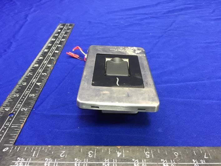
Click to zoom
Application Details
- Equipment Class
- DXX - Part 15 Low Power Communication Device Transmitter
- Date of Grant
- Nov 29, 2020
- Application Purpose
- Original Equipment
- Date of Application
- Nov 29, 2020
- Equipment Note
- RS485 Fingerprint Reader
- Frequency Range
- 13.56000000 - 13.56000000
- Company
- ZKTECO CO., LTD.
- Country
- China
Documents & Files
Document Text
Text extracted from the exhibit documents filed with the FCC. Open a document above to read the original.
Users Manual
Installation Guide FR1500S Version: 1.0 Due to regular upgrades of systems and products, ZKTeco could not guarantee exact consistency between the actual product and the written information in this manual. Installation 1 Dimensions(mm) Remove both the screws STEP 1 Procedure to be followed before installation Note: Not all the devices have the fingerprint cover. The real product prevails. 77.3 121.3 7.1 38.0 Installation 2 Take out the front panel as shown below STEP 2 Method 1: Mounting on the standard Single gang junction box Lay the cables from the desired hole in Single gang junction box and fix the machine part to the box part. The Single gang junction box's size recommendations: Location column: 83.3mm Inside of the box Depth: Minimum 36mm Outside the box size: maximum length 120mm , maximum width 76mm 8 3 . 3 m m 3 6 m m 1 2 0 m m 7 6 m m 3 Method 2: Mounting inside the wall STEP 1 Place the mounting sticker to the place where device needs to be installed STEP 2 Drill fixing holes and dig mounting groove deep of 36mm 10 11 Instruction for the Mounting Paper Before the device is fastened, please stick the paper to the place where you want to install it, then make holes and lay cables according to the mounting paper. Fixing Hole Fixing Hole Mounting Paper (only for your reference) The depth of the installation groove is 36mm wall 3 6 m m STEP 3STEP 4 If cables need to be laid from behind then it must be done before installing Install the device with the screws After installing the back plate attach the machine part in the same reverse manner as shown in previous page STEP 5 Wiring Terminals This reader is an innovative Silk ID reader. It needs to be connected to a host machine so that fingerprint information can be transferred through Rs485. Reader wires nomenclature and Dip Switch Dip Switch RED 12V BLACK GND YELLOW 485+ PURPLE 485- BLACK GND +12V GND 485- 485+ E X T - + DC12V 1 2 8 Connected as inBIO Pro Reader(with External 485), maximum 8 readers can be connected. The reader requires a separate power supply. 4 1. Connection with a Control Panel. STATE PWR EXTRS485 PCRS485 SWITCH so on...... DC12V - + - + > Dip Switch setting with control panel Terminal Resistance 8 4 2 1 12 3 4 5 6 Switch SettingSwitch Setting Address Address 1 2 3 4 5 6 7 8 12 3 4 5 6 12 3 4 5 6 12 3 4 5 6 12 3 4 5 6 12 3 4 5 6 12 3 4 5 6 12 3 4 5 6 1 2 3 4 5 6 5 Working Principle Number 1, 2, 3, 4 of the dip switch are used to set the address of RS485, 5 is the restart switch, and 6 is the Terminal Resistance. Number 5 is the restart switch: dial up and dial down. The machine will restart. The right side figure shows the address number setting. Number 6 switch is used to set the terminal resistance in RS485. Communication: If the 485 communication wire is longer, than 100 meters, it is needed to set the number 6 dip switch of the last reader to ON state, that is parallel a terminal resistance of 120 ohm between 485+ and 485-. +12V GND GND 485+ 485- 2. Connection with a Standalone Access Controller 6 + 1 2 V G N D 4 8 5 A G N D 4 8 5 B 1 4 +12V GND 1 5 GND 485A 485B When using the reader with Standalone access controller device, please move the dial code “1” to the ON position as shown above. Verification Proccess 7 Safety Precautions 1. Power cable should be connected at last, after all the wiring. If the device is working abnormally, immediately shutdown the device. 2. Please read the terminals description and wiring by rule strictly. Any damage caused by improper operations will be out of the range of our guarantee. 3. Please connect the ‘GND’ before all the other wiring especially under the serious electrostatic environment. 4. Keep the exposed part of wire less than 5mm to avoid unexpected connection, and result in machinery damage. 5. If the distance between power supply and device is little long, please do not use the Internet cable or other types of cable instead. When choosing the power supply cable, you should consider that the transmission distance may cause voltage attenuation. Connection with the controller: Unsuccessful:LED flashes blue light twice every one second. Successfully:LED flashes blue light once every one second. When verifying the fingerprint or punching the card: Successful Verification: Authentication error: Data Error: Timeout: Authentication failed: Red LED, two short BEEP No rights:Red LED, three short BEEP Verify unfinished: Red LED flashes three times Green LED lights, short BEEP Red LED lights, two short and a long BEEP Red LED lights, one short and a long BEEP Red LED lights, four short BEEP Copyright © 2020 ZKTECO CO., LTD. All Rights Reserved. Tangxia Town, Dongguan, China. No. 26, 188 Industrial Road, Phone : +86 769 - 82109991 Fax : +86 755 - 89602394 www.zkteco.com FCC warning: Any Changes or modifications not expressly approved by the party responsible for compliance could void the user's authority to operate the equipment. Note: This equipment has been tested and found to comply with the limits for a Class B digital device, pursuant to part 15 of the FCC Rules. These limits are designed to provide reasonable protection against harmful interference in a residential installation. This equipment generates uses and can radiate radio frequency energy and, if not installed and used in accordance with the instructions, may cause harmful interference to radio communications. However, there is no guarantee that interference will not occur in a particular installation. If this equipment does cause harmful interference to radio or television reception, which can be determined by turning the equipment off and on, the user is encouraged to try to correct the interference by one or more of the following measures: -Reorient or relocate the receiving antenna. -Increase the separation between the equipment and receiver. -Connect the equipment into an outlet on a circuit different from that to which the receiver is connected. -Consult the dealer or an experienced radio/TV technician for h…
Text truncated - open the document above for the full version.
Attestation Statements
ZKTECO CO., LTD. Date: 2020-11-26 To: Federal Communications Commission 7435 Oakland Mills Road Columbia, MD FCC ID: 2AJ9T-FR1500SM To Whom It May Concern: This letter is to ascertain that ZKTECO CO., LTD. EUT:RS485 Fingerprint Reader MODEL No.: FR1500S、FR1500A、FR1500A-WP、FR1500、FR1500-WP Has been the units used for conducting FCC compliance testing, the SDoC part will be tested by EMTEK (SHENZHEN) CO., LTD. If you have any question or concerns, pls. contact us. Sincerely, Client’s signature : Client’s name / title : ZhonglieGey Contact information / address: ZKTECO CO., LTD. / No.26,Pingshan 188 Industry zone,Tangxia Town,Dongguan City,Guangdong Province,China 523728
Cover Letter(s)
Rev11/20/07 ZKTECOCO.,LTD. FederalCommunicationsCommission AuthorizationandEvaluationDivision ConfidentialityRequestregardingapplicationforcertificationof FCCID:2AJ9T-FR1500SM PursuanttoSections0.457and0.459oftheCommission’sRules,weherebyrequestconfidential treatmentofinformationaccompanyingthisapplicationasoutlinedbelow: ExhibitTypeFileName BlockDiagram,Schematics,Operational Description, BlockDiagram OperationDescription schematicdiagram Theabovematerialscontaintradesecretsandproprietaryinformationnotcustomarilyreleasedto thepublic.Thepublicdisclosureofthesematerialsmaybeharmfultotheapplicantandprovide unjustifiedbenefitstoitscompetitors. ZhonglieGe ZKTECOCO.,LTD.
Cover Letter(s)
ZKTECOCO.,LTD. FederalCommunicationsCommission AuthorizationandEvaluationDivision 1435OaklandMillsRoad Columbia,MD21046 Date:2020-11-23 SUBJECT:FCCApplicationforFCCID:2AJ9T-FR1500SM ToWhomItMayConcern: We,theundersigned,herebyauthorizeLisaWangatEMTEK(SHENZHEN)CO.,LTD.on ourbehalf,toapplytotheFederalCommunicationsCommissiononourequipment.Any andallactscarriedoutbyEMTEK(SHENZHEN)CO.,LTD.onourbehalfshallhavethe sameeffectasactsofourown. ThisistoadvisethatweareinfullcompliancewiththeAnti-DrugAbuseAct.We,the applicant,arenotsubjecttoadenialoffederalbenefitspursuanttoSection5301ofthe Anti-DrugActof1988,21USC853a,andnopartytotheapplicationissubjecttoadenial offederalbenefitspursuanttothatsection. ZhonglieGey/Engineer ZKTECOCO.,LTD.
External Photos
TRF NO. FCC15/A Page 1 of 4 Report No.: ES201023037W EUT EXTERNAL PHOTOGRAPHS TRF NO. FCC15/A Page 2 of 4 Report No.: ES201023037W TRF NO. FCC15/A Page 3 of 4 Report No.: ES201023037W TRF NO. FCC15/A Page 4 of 4 Report No.: ES201023037W ----------------The end----------------
Internal Photos
TRF NO. FCC15/A Page 1 of 6 Report No.: ES201023037W EUT INTERNAL PHOTOGRAPHS TRF NO. FCC15/A Page 2 of 6 Report No.: ES201023037W TRF NO. FCC15/A Page 3 of 6 Report No.: ES201023037W TRF NO. FCC15/A Page 4 of 6 Report No.: ES201023037W TRF NO. FCC15/A Page 5 of 6 Report No.: ES201023037W Antenna TRF NO. FCC15/A Page 6 of 6 Report No.: ES201023037W ----------------The end----------------
Test Report
Report No. ES201023037W Page 1 of 33 Ver.1.0 TEST REPORT Product Name : RS485 Fingerprint Reader Model Number : FR1500S、FR1500A、FR1500A-WP、 FR1500、FR1500-WP FCC ID : 2AJ9T-FR1500SM Prepared for : ZKTECO CO.,LTD. Address : No.26,Pingshan 188 Industry zone,Tangxia Town,Dongguan City,Guangdong Province,China 523728 Prepared by : EMTEK (SHENZHEN) CO., LTD. Address : Building 69, Majialong Industry Zone, Nanshan District, Shenzhen, Guangdong, China Tel: (0755) 26954280 Fax: (0755) 26954282 Report Number : ES201023037W Date(s) of Tests : Nov. 06, 2020 to Nov. 13, 2020 Date of issue : Nov. 15, 2020 Report No. ES201023037W Page 2 of 33 Ver.1.0 Table of Contents 1 EUT TECHNICAL DESCRIPTION ........................................................................................................... 4 2 SUMMARY OF TEST RESULT ................................................................................................................ 5 3 TEST METHODOLOGY ........................................................................................................................... 6 3.1 GENERAL DESCRIPTION OF APPLIED STANDARDS ................................................................ 6 3.2 MEASUREMENT EQUIPMENT USED .......................................................................................... 6 3.3 DESCRIPTION OF TEST MODES ................................................................................................. 7 4 FACILITIES AND ACCREDITATIONS ..................................................................................................... 8 4.1 FACILITIES .................................................................................................................................... 8 4.2 LABORATORY ACCREDITATIONS AND LISTINGS ..................................................................... 8 5 TEST SYSTEM UNCERTAINTY .............................................................................................................. 9 6 SETUP OF EQUIPMENT UNDER TEST ............................................................................................... 10 6.1 RADIO FREQUENCY TEST SETUP 1 ......................................................................................... 10 6.2 RADIO FREQUENCY TEST SETUP 2 ......................................................................................... 10 6.3 CONDUCTED EMISSION TEST SETUP ..................................................................................... 11 6.4 BLOCK DIAGRAM CONFIGURATION OF TEST SYSTEM ......................................................... 12 6.5 SUPPORT EQUIPMENT .............................................................................................................. 12 7 TEST REQUIREMENTS ......................................................................................................................... 13 7.1 OCCUPIED BANDWIDTH ............................................................................................................ 13 7.2 FREQUENCY STABILITY ............................................................................................................ 15 7.3 RADIATED SPURIOUS EMISSION ............................................................................................. 17 7.4 CONDUCTED EMISSION TEST .................................................................................................. 30 8 ANTENNA APPLICATION ..................................................................................................................... 33 8.2 RESULT .......................................................................................................................................... 33 Report No. ES201023037W Page 3 of 33 Ver.1.0 TEST RESULT CERTIFICATION Applicant : ZKTECO CO.,LTD. Address: No.26,Pingshan 188 Industry zone,Tangxia Town,Dongguan City,Guangdong Province,China 523728 Manufacturer : ZKTECO CO.,LTD. Address: No.26,Pingshan 188 Industry zone,Tangxia Town,Dongguan City,Guangdong Province,China 523728 EUT : RS485 Fingerprint Reader Model Name : FR1500S、FR1500A、FR1500A-WP、FR1500、 FR1500-WP (All models covered in this report are the same with each other, except for different model No.,We choose FR1500S as the final test prototype) Trademark : N/A Measurement Procedure Used: APPLICABLE STANDARDS STANDARD TEST RESULT FCC 47 CFR Part 2, Subpart J FCC 47 CFR Part 15, Subpart C PASS The above equipment was tested by EMTEK(SHENZHEN) CO., LTD. The test data, data evaluation, test procedures, and equipment configurations shown in this report were made in accordance with the procedures given in ANSI C63.10 (2013) and the energy emitted by the sample EUT tested as described in this report is in compliance with the requirements of FCC Rules Part 2 and Part 15.225. The test results of this report relate only to the tested sample identified in this report. Date of Test : Nov. 06, 2020 to Nov. 13, 2020 Prepared by : Lance Li/Editor Reviewer : Sewen Guo /Supervisor Approve & Authorized Signer : Lisa Wang/Manager Report No. ES201023037W Page 4 of 33 Ver.1.0 1 EUT TECHNICAL DESCRIPTION Characteristics Description Device Type: RFID Modulation: ASK modulation Test sample 1# Operating Frequency Range(s): 13.553-13.567MHz Channel Frequency: 13.56MHz Number of Channels: 1 channel Antenna Type : PCB antenna Antenna Gain : 0.5 dBi Power Supply DC12V from adapter Test Voltage AC 120V/60Hz Adapter Model :ADS-40SI-12-3 Input:AC100-240V,50/60Hz,1.0A Max Output:DC12V,3.0A Temperature Range -20°C ~ +50°C Note: for more details, please refer to the User’s manual of the EUT. Report No. ES201023037W Page 5 of 33 Ver.1.0 2 SUMMARY OF TEST RESULT FCC Part Clause Test Parameter Verdict Remark 2.1049 Occupied Bandwidth PASS 15.225(e) Frequency stability PASS 15.225(d) 15.209 Radiated Spurious Emissions PASS 15.207 Conducted Emission PASS NOTE1: N/A (Not Applicable) RELATED SUBMITTAL(S) / GRANT(S): This submittal(s) (test report) is intended for FCC ID: 2AJ9T-…
Text truncated - open the document above for the full version.
Test Setup Photos
Setup photos ConducTED EMISSION TEST
Test Setup Photos
TRF NO. FCC15/A Page 1 of 1 Report No.: ES201023037W TEST SETUP PHOTOGRAPHS 1.1. Photos of Radiation Emission Measurement Spurious Emission Test Setup (Below 30MHz) Spurious Emission Test Setup (Below 1GHz) ----------------The end----------------
Contact Information
Applicant
Zhonglie Ge(Engineer)
Test Firm
EMTEK (Shenzhen) Co., Ltd.Lisa Wang
[email protected]86 755 26954280
Technical Specifications
| # | Rule Parts | Frequency Range | Power Output |
|---|---|---|---|
| 1 | 15C | 13.56 MHz - 13.56 MHz | - |
Other Applications from ZKTECO CO., LTD.
2AJ9T-21014
Jan 09, 2026Smart Access Control Terminal
Equipment Class
DCD - Part 15 Low Power Transmitter Below 1705 kHz
2AJ9T-75601
Dec 15, 2025Remote controller
Equipment Class
DSC - Part 15 Security/Remote Control Transmitter
2AJ9T-75501
Dec 15, 2025Smart Lock
Equipment Class
DXX - Part 15 Low Power Communication Device Transmitter
2AJ9T-10201
Sep 23, 2025Smart Identification Terminal
Equipment Class
DXX - Part 15 Low Power Communication Device Transmitter2AJ9T-107601
Sep 08, 2024Base Station
Equipment Class
DSS - Part 15 Spread Spectrum Transmitter