2AJFZ-GROMVLVLine
X-Media Tech, Inc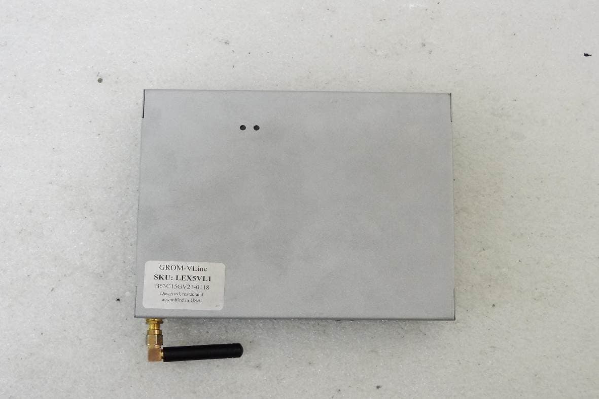
Click to zoom
Application Details
- Equipment Class
- DTS - Digital Transmission System
- Date of Grant
- Jan 21, 2020
- Application Purpose
- Original Equipment
- Date of Application
- Jan 19, 2020
- Equipment Note
- VLine
- Frequency Range
- 2412.00000000 - 2462.00000000
- Company
- X-Media Tech, Inc
- Country
- United States
Documents & Files
Document Text
Text extracted from the exhibit documents filed with the FCC. Open a document above to read the original.
Users Manual
INSTALLATION MANUAL www.gromaudio.com www.gromaudio.com/support.html LEX5 CONTENTS Package contents......................................................................................................3 CHAPTER 1 — INSTALLATION.........................................................................3 1.1 Before Installation 3 1.2 Tools 3 1.3 Vehicle Installation 3 1.4 Safety Guidelines & Appropriate Use 4 Connect supplied Display Harness Cable to factory Display................5 Connect VLine Interface cable to Factory Head unit..............................6 Connecting to VLine....................................................................................6 Routing the GPS Antenna....................................................................................7 Routing the Microphone..........................................................................................8 Mounting the VLine Module................................................................................... 9 Understanding VLine Ports....................................................................................10 CHAPTER 2 — GETTING STARTED.................................................................. 11 SUPPORT.........................................................................................................13 WARRANTY......................................................................................................13 EIGHTEEN MONTH (18) LIMITED WARRANTY GRANT OF LICENSE.........................................................................................14 OPERATIONAL WARNING AND SAFETY INSTRUCTIONS.............................15 3 1.1 Before Installation Before starting work with any wiring, please wait 90 seconds after turning the Ignition to the OFF position and disconnecting the negative (-) terminal of the battery. This is to ensure that no SRS airbags faults are triggered during the installation when disassembling the vehicle’s panels and wiring connections for the VLINE module installation. Please review the entire manual to familiarize yourself of the VLINE module and the installation requirements before installing the unit and using it. 1.2 Tools Have Tools ready for disassembling the dashboard panels to remove the stereo. Some basic tools will be required for stereo removal and installation, Plastic prying tools, Phillips head screwdriver,10mm socket and ratchet. Additional tools may be required depending on vehicle and installation preference. 1.3 Vehicle Installation Each model vehicle dissembles differently. The removal of the stereo and CHAPTER 1 — INSTALLATION PACKAGE CONTENTS GROM-VLINE SYSTEM GVMF Display Harness Microphone MCFTOY Power Harness USB Extension cable VLine module GPS Antenna wiring installation requires special technical skills and experience. If you do not feel comfortable doing the installation please consult with your local car audio shop or installation professional for instructions or assistance if necessary. Carefully remove the factory Stereo and Display out of the dash cavity with proper tools. It may be necessary to disconnect items surrounding the stereo and display to remove them and gain access to the back of the stereo to make your connections. 1.4 Safety Guidelines & Appropriate Use By using VLine you agree: •to operate VLine only when there are safe driving conditions; •to follow any applicable state and traffic laws; •to keep an eye on the road at all time while driving; •do not attempt to play video (such as YouTube) on a display while the vehicle is in motion; •do not use VLine without running the engine for the extended period of time as it can drain the battery. Do not use Vline in a manner that would distract the driver or that may otherwise cause injury or death to vehicle occupants or bystanders. IT IS ILLEGAL IN MOST STATES OF THE UNITED STATES AND MAY BE ILLEGAL IN OTHER JURISDICTIONS FOR ANY TELEVISION OR OTHER VIDEO DISPLAY, STREAM, TRANSMISSION OR BROADCAST TO BE VISIBLE TO THE DRIVER WHILE THE VEHICLE IS IN MOTION. YOU AGREE NOT TO USE ANY VISUAL COMPONENT OF VLine WHILE IN CONTROL OF A MOVING VEHICLE WHERE DOING SO WOULD BE ILLEGAL OR DANGEROUS TO VEHICLE OCCUPANTS OR BYSTANDERS. DOING OTHERWISE CAN LEAD TO SERIOUS INJURY OR DEATH TO YOU AND OTHERS. PLEASE FIND A SAFE PLACE TO PARK AND ENGAGE THE PARKING BRAKE BEFORE VIEWING ANY VIDEO DISPLAYS, STREAMS, TRANSMISSION, OR BROADCAST AVAILABLE THROUGH VLINE. 4 5 Video Display Port Connect supplied Display Harness Cable to factory Display Locate BLUE Display port on rear of Multi Display ECU. If the port is Empty, plug in supplied video cable (GVMF) into port and leave female portion of cable with nothing attached. If there is cable plugged in, disconnect factory Display cable (typically Blue in color). Then plug in supplied Y cable and reconnect disconnected cable into female plug of the supplied Display cable. Display HarnessPower Audio Harness Power Audio Connector Connect VLine Interface cable to Factory Head unit Located 12-pin connector and unplug. Plug in supplied Power Audio Wiring Harness Interface cable (MCFTOY). Reconnect back what was disconnected from the rear of the stereo back into the female plug of the supplied interface cable. Connecting to VLine Route the unused end of Display Cable and Power Audio Cable to the VLine module and connect them to the correctly labeled ports. 6 7 Routing the GPS Antenna The GPS Antenna module is magnetic as well as supplied with double sided tape. It can be mounted to the top of dashboard or to outside of vehicle whichever you prefer. Route to desired location. We recommend mounting on inside of vehicle on passenger side of the Dashboard as shown below. Plug the GPS antenna into the port labeled CAMERA AV1 on the VLine Module Routing the Microphone Route microphone to a location where it will be able to pick up voice clearly. We recommend to mount MIC nearby the rear view mirror but not directly on windshield glass. Avoid sticking…
Text truncated - open the document above for the full version.
Users Manual
USER GUIDE www.gromaudio.com www.gromaudio.com/support.html CONTENTS Chapter 1 — Getting started........................................................................3 Setting up WiFi.........................................................................................................3 Chapter 2 — Google Apps and Maps............................................................6 2.1 Installing Google Apps (GApps).......................................................................6 2.2 Signing into Play Store.....................................................................................9 2.3 Maps Setup.....................................................................................................13 2.4 Voice Activation Button for Navigation.......................................................15 2.5 Changing Text-to-Speech Output Voice......................................................16 Chapter 3 — MEDIA PLUGINS......................................................................18 3.1 Spotify.............................................................................................................19 3.2 Web Radio......................................................................................................20 3.3 Google music ................................................................................................21 3.4 Local Music (USB, MicroSD) .........................................................................22 3.5 A2DP Bluetooth Music Streaming................................................................23 Setting up Bluetooth for A2DP music streaming..............................................23 A2DP stream..........................................................................................................24 Chapter 4 — OTA SOFTWARE UPDATES......................................................25 Chapter 5 —SUPPORT..................................................................................27 Periodic Apps Cleanup.........................................................................................27 FAQ.........................................................................................................................28 Additional Support................................................................................................28 3 Settings CHAPTER 1 – Getting Started Setting up Wifi The VLINE module will require an internet connection while on the road to take advantage of majority of its features. Two ways to provide internet to VLine: 1. Smartphone tethering and hotspot On iPhone: Home->Settings->Personal Hotspot .Turn it on and set up network name and password. On Android: Home->Settings->Wireless Networks -> More -> Tethering & Portable Hotspot -> Portable Wifi Hotspot. Tap to turn it on, and set up network name and password. 2. Dedicated modem hotspot with SIM card and data plan - either USB modem or any other kind of portable modem. Check with the carrier of your choice on the availability of internet only data plans. Resources: https://gromaudio.com/blog/2018/09/how-to-get-internet-to-car/ Once you setup Wifi Hotspot in your vehicle, connect VLine to the internet. Go to VLine--> Settings 4 Vline Setup CBCI-1EA1-2.4 ATT896 CBCI-44AB-2.4 On Settings Wireless & networks Wi-Fi Data usageMore Display Sound & notification Settings Bluetooth Device Go into WiFi Settings Select WiFi channel to connect 5 Vline Setup CBCI-1EA1-2.4 ATT896 CBCI-44AB-2.4 On Settings PPPaaasssssswwwooorrrddd SSShhhooowww pppaaasssssswwwooorrrddd AAAdddvvvaaannnccceeeddd oooppptttiiiooonnnsss VVVLLLiiinnneee SSSeeetttuuuppp CONNECTCANCEL Enter [Password] and select CONNECT NOTE: Please check with your mobile carrier for hotspot data usage limits If you are using your smartphone to tether internet to VLine. Depending on mobile provider you might be subject to mobile data and tethering charges. 6 Settings CHAPTER 2 — Google Apps and Maps 2.1 Installing Google Apps (Gapps) Installing Google Apps will allow you to access Google Play Store to down- load any applicatition to VLine, and to use voice assistant (RED) button. Once GApps are installed, you can download and use any music apps and maps from Google Play Market. To install the Gapps (Google Apps) Package: 1. Connect VLine to internet. Check Chapter 1, we recommend to connect to home Wifi to install GApps, so you do not spend your mobile data. 2. Go to Settings 7 About Device Accounts Language & input Backup & reset AccessibilityDate & time Printing About deviice System Settings VLine system updates Legal information Regulatory information Status of the battery, network, and other information System updates About device Scroll down all the way to the bottom and select “About Device” Then select “VLINE System Updates 8 Gapps VL1.0.1.0 Grom OTA Installed version Check to availabke updates Check to update Additional System Updates Install Gapps Gapps VL1.0.1.0 Grom OTA Installed version Check to available updates Check to update Additional System Updates Install Gapps Download size: 109.2MiB Install Gapps VLine Update System Install Select “Install Gapps” Press the “Install” button to apply update. Wait for update to download and apply. The VLINE will restart during the process (this may take up to 10 minutes) If system does not boot up within 15 minutes, please turn off Ignition and wait 1 minute and then turn ignition on again. YouTube demo video: bit.ly/vline_gapps 9 Settings APPS SHORTCUTSPLUGINS Settings Voice Search Play Store You Tube Choose App 2.2 Signing into Play Store and Adding Apps to Home Screen Select Empty Spot You Wish to Add Icon to Select the Apps/Shortcuts/Plugins you wish to add, in this case the “Play Store” Application. 10 Settings Play Store Enter your email Sign in to get the most out of your device. Learn more Or create a new account MORE Add your account Signing onto Google Account Select the Play Store Icon First time signing into the Google Play Store, you …
Text truncated - open the document above for the full version.
Cover Letter(s)
深圳市信高维科技有限公司 信高维科技有限公司 Shenzhen Signalwell Technology CO.,LTD 第1页 产品规格书 PRODUCT SPECIFICATION Customer: Customer’s part number: Product description: 2.4G antenna Uni Link’s part number: SW-2.4G-024 Issue Date: 2015-01-28 Note: 2.4G,3dbi,SMA-male connector.4.5cm. 客户签名 深圳市信高维科技有限公司 核准 审核 检查 核准 审核 检查 深圳市信高维科技有限公司 Shenzhen Signalwell Technology Co.,1td. 联系人:Accen MOBILE:86+15813729133 地址:深圳市龙岗龙园路98~100号 E-mail:[email protected] 深圳市信高维科技有限公司 信高维科技有限公司 Shenzhen Signalwell Technology CO.,LTD 第2页 一、目录 1、产品技术指标(PRODUCT TECHNICAL SPECIFICATION) 中心频率 Center Frequency (MHz) 2.4GHZ 频带宽度Bandwidth (MHz) 100MHZ 输入阻抗Input Impendence (Ω) 50 电压驻波比V.S.W.R ≤1.5 功率容量 Maximun power lnput-watts 50W 极化强度(Polarization Intensity) 垂直 Vertical 电源电压(Supply Voltage) DC3.0~5.0V 躁声系数(The Sound Coefficient) ≤1.5dB 增益Gain (dBi) 3dBi 连接器型号 Connector Type SMA-Male 工作温度(Operating Temperature) -40°C~+85°C 贮藏温度(Storing Temperature) -40°C~+90°C 外罩材料(Radome material) TPE、ABS 尺寸 Dimension(cm) 4.5cm 深圳市信高维科技有限公司 信高维科技有限公司 Shenzhen Signalwell Technology CO.,LTD 第3页 2、产品图片(Product pictures) 3、产品规格图(Product specification chart) 深圳市信高维科技有限公司 信高维科技有限公司 Shenzhen Signalwell Technology CO.,LTD 第4页 4、电气特性(ELECTRIC APPLIANCE CHARACTERISTICS) 项目ITEM 测试环境TEST CONDITION 规格SPECIFICATION 1 返回损耗 Return Loss 使用Agilent网络分析仪8753ET测量天 线S11之返回损耗参数 Using Agilent Network Analyzer 8753ET to Measure Antenna S11 Return Loss Characteristics. 2 电压驻波比 VSWR 使用Agilent网络分析仪8753ET测量天 线S11之电压驻波比参数 Using Agilent Network Analyzer 8753ET to Measure Antenna S11 VSWR Characteristics. 3 阻抗 Smith chart 使用Agilent网络分析仪8753ET测量天 线S11之史密斯阻抗参数 Using Agilent Network Analyzer 8753ET to Measure Antenna S11 Gain Response Characteristics. 4 增益效应 Gain response 使用Agilent网络分析仪8753ET测量天 线S21之史密斯阻抗参数 Using Agilent Network Analyzer 8753ET to Measure Antenna S21 Gain Response Characteristics. 深圳市信高维科技有限公司 信高维科技有限公司 Shenzhen Signalwell Technology CO.,LTD 第5页 5、耐久性测试(DURABILITY) 1 盐雾试验 SAIT SPRAY TEST 盐水喷雾试验:依GB1266-86标准 蒸馏水:一次蒸馏 PH6.5~7 喷雾量:1.4me80cm²/h 压缩空气压力:1Kgf/ cm² 试验相对度:98° 温度:45°~47° 压力温度:35° 测试时间:96hr 所有规格变华 范围初始值 30% All characteristic range is 30% of the initial value 2 高温试验 HEAT TEST 在85+2°C环境中放96小时,再放在正 常环境中30分钟后进行测试 85+2°C for 96 hours, after keep in normal condition for 30mim the to test. 3 温试验 HUMIDITY TEST 在40+2°C 90-95%RH环境中放96小时, 再放在正常环境中30分钟后进行测试 40+2°C 90-95%RH for 96hours, after keep in normal condition for 30mim the to test. 4 底温试验 COLD TEST 在-40+2°C 环境中放96小时,再置放正 常环境中30分钟后进行测试 -40+2°C for 96hours, after keep in normal condition for 30mim the to test. 深圳市信高维科技有限公司 信高维科技有限公司 Shenzhen Signalwell Technology CO.,LTD 第6页 6、测试情况(Performanc testing) 1.Impedance 深圳市信高维科技有限公司 信高维科技有限公司 Shenzhen Signalwell Technology CO.,LTD 第7页 2. VSWR 深圳市信高维科技有限公司 信高维科技有限公司 Shenzhen Signalwell Technology CO.,LTD 第8页 3. Return loss
External Photos
FCC ID: 2AJFZ-GROMVL International Standards Laboratory Corp. APPENDIX 2 Photographs of EUT FCC ID: 2AJFZ-GROMVL International Standards Laboratory Corp. EUT 1 EUT 2 FCC ID: 2AJFZ-GROMVL International Standards Laboratory Corp. EUT 3 EUT 4 FCC ID: 2AJFZ-GROMVL International Standards Laboratory Corp. EUT 5 EUT 6
ID Label/Location Info
FCC ID LABEL FORMAT AND LOCATION Applicant: X-Media Tech Inc. FCC ID: 2AJFZ-GROMVL
Internal Photos
FCC ID: 2AJFZ-GROMVL International Standards Laboratory Corp. APPENDIX 3 Photographs of EUT FCC ID: 2AJFZ-GROMVL International Standards Laboratory Corp. EUT 1 EUT 2 FCC ID: 2AJFZ-GROMVL International Standards Laboratory Corp. EUT 3 EUT 4 FCC ID: 2AJFZ-GROMVL International Standards Laboratory Corp. EUT 5 EUT 6 FCC ID: 2AJFZ-GROMVL International Standards Laboratory Corp. EUT 7 EUT 8 FCC ID: 2AJFZ-GROMVL International Standards Laboratory Corp. EUT 9 EUT 10 FCC ID: 2AJFZ-GROMVL International Standards Laboratory Corp. EUT 11 EUT 12 FCC ID: 2AJFZ-GROMVL International Standards Laboratory Corp. EUT 13 EUT 14
RF Exposure Info
FCC ID: 2AJFZ-GROMVL International Standards Laboratory Maximum Permissible Exposure (MPE) Standard Applicable According to §1.1307(b)(1), systems operating under the provisions of this section shall be operated in a manner that ensure that the public is not exposed to radio frequency energy level in excess of the Commission’s guideline. According to §1.1310 and §2.1091 RF exposure is calculated. Limits for Maximum Permissive Exposure (MPE) Frequency Range (MHz) Electric Field Strength (V/m) Magnetic Field Strength (A/m) Power Density (mW/cm 2 ) Averaging Time (minute) Limits for General Population/Uncontrolled Exposure 0.3-1.34 614 1.63 *(100) 30 1.34-30 824/f 2.19/f *(180/f 2 ) 30 30-300 27.5 0.073 0.2 30 300-1500 / / F/1500 30 1500-15000 / / 1.0 30 F = frequency in MHz * = Plane-wave equipment power density FCC ID: 2AJFZ-GROMVL International Standards Laboratory FCC Maximum Permissible Exposure (MPE) Evaluation: The worst case of Average power Power measurement: refer to Part15.247 report for details. Wi-Fi Frequency Range (MHz) Channels Peak / Average Power Modulation Technology 802.11b 2412 – 2462(DTS) 11 18.89dBm (PK) DSSS 802.11g 2412 – 2462(DTS) 11 23.40dBm (PK) OFDM 802.11n HT20 2412 – 2462(DTS) 11 23.18dBm (PK) Maximum output power at antenna input terminal: 23.4 (dBm) Maximum output power at antenna input terminal: 218.7761624 (mW) Tune-Up power Tolerance: 0.5 dB Duty cycle: 100 (%) Maximum Pav : 245.4708916 (mW) Antenna gain (typical): 3 (dBi) Maximum antenna gain: 1.995262315 (numeric) Prediction distance: 20 (cm) MPE limit for uncontrolled exposure at prediction 1 (mW/cm^2) Power density at predication frequency at 20 (cm) 0.0974878 (mW/cm^2) Prediction of MPE limit at a given distance Equation from page 18 of OET Bulletin 65, Edition 97-01 S=PG/4πR 2 Where: S = Power density P = Power input to antenna G = Power gain of the antenna in the direction of interest relative to an isotropic radiator R = Distance to the center of radiation of the antenna Measurement Result: The predicted power density level at 20 cm is 0.0974878 mW/cm2. This is below the uncontrolled exposure limit of 1 mW/cm 2 . FCC ID: 2AJFZ-GROMVL International Standards Laboratory BT mode: Maximum Permissible Exposure (MPE) Evaluation: The worst case of Average power Power measurement: refer to Part15.247 report for details. BDR Mode Frequency (MHz) Peak Reading Power (dBm) Cable Loss Output Power (dBm) Output Power (W) Limit (W) Low -1.33 2.50 1.17 0.00131 1 Mid -1.00 2.50 1.50 0.00141 1 High -1.41 2.50 1.09 0.00128 1 Maximum output power at antenna input terminal: 1.5 (dBm) Maximum output power at antenna input terminal: 1.412537545 (mW) Tune-Up power Tolerance: 1 dB Duty cycle: 100 (%) Maximum Pav : 1.77827941 (mW) Antenna gain (typical): 3 (dBi) Maximum antenna gain: 1.995262315 (numeric) Prediction distance: 20 (cm) MPE limit for uncontrolled exposure at prediction 1 (mW/cm^2) Power density at predication frequency at 20 (cm) 0.0007062 (mW/cm^2) Prediction of MPE limit at a given distance Equation from page 18 of OET Bulletin 65, Edition 97-01 S=PG/4πR 2 Where: S = Power density P = Power input to antenna G = Power gain of the antenna in the direction of interest relative to an isotropic radiator R = Distance to the center of radiation of the antenna Measurement Result: The worst power density is 0.0007062 mW/cm^2 which is less than 1 mW/cm^2. ~ end ~
Test Report
Page: 1 of 54 TEST REPORT of FCC Part 15 Subpart C New Application; Class I PC; Class II PC Product : VLine Brand: GROM Model: VL2 Model Difference: N/A FCC ID: 2AJFZ-GROMVL FCC Rule Part: §15.247, Cat: DTS Applicant: X-Media Tech Inc. Address: 519 Marine View Ave #H, Belmont, CA, 94002, United States Test Performed by: International Standards Laboratory Corp. <LT Lab.> *Site Registration No. BSMI: SL2-IN-E-0013; MRA TW0997; TAF: 0997; IC: IC4067B-4; *Address: No. 120, Lane 180, Hsin Ho Rd. Lung-Tan Dist., Tao Yuan City 325, Taiwan *Tel : 886-3-407-1718; Fax: 886-3-407-1738 Report No.: ISL-19LR322FCDTS Issue Date : 2019/12/19 Test results given in this report apply only to the specific sample(s) tested and are traceable to national or international standard through calibration of the equipment and evaluating measurement uncertainty herein. This test report shall not be reproduced except in full, without the written approval of International Standards Laboratory Corp. -2 of 54- FCC ID: 2AJFZ-GROMVL International Standards Laboratory Corp. Report Number: ISL-19LR322FCDTS VERIFICATION OF COMPLIANCE Applicant: X-Media Tech Inc. Product Description: VLine Brand Name: GROM Model No.: VL2 Model Difference: N/A FCC ID: 2AJFZ-GROMVL Date of test: 2019/10/29 ~ 2019/12/18 Date of EUT Received: 2019/10/29 We hereby certify that: All the tests in this report have been performed and recorded in accordance with the standards de- scribed above and performed by an independent electromagnetic compatibility consultant, Interna- tional Standards Laboratory Corp. The test results contained in this report accurately represent the measurements of the characteristics and the energy generated by sample equipment under test at the time of the test. The sample equip- ment tested as described in this report is in compliance with the limits of above standards. Test By: Date: 2019/12/19 Bill Huang / Engineer Prepared By: Date: 2019/12/19 Gigi Yeh / Sr. Engineer Approved By: Date: 2019/12/19 Jerry Liu / Technical Manager -3 of 54- FCC ID: 2AJFZ-GROMVL International Standards Laboratory Corp. Report Number: ISL-19LR322FCDTS Version Version No. Date Description 00 2019/12/19 Initial creation of document Uncertainty of Measurement Description Of Test Uncertainty Conducted Emission (AC power line) 2.586 dB Field Strength of Spurious Radiation ≤30MHz: 2.96dB 30-1GHz: 4.22 dB 1-40 GHz: 4.08 dB Conducted Power 2.412 GHz: 1.30 dB 5.805 GHz: 1.55 dB Power Density 2.412 GHz:1.30 dB 5.805 GHz: 1.67 dB Frequency 0.0032% Time 0.01% DC Voltage 1% -4 of 54- FCC ID: 2AJFZ-GROMVL International Standards Laboratory Corp. Report Number: ISL-19LR322FCDTS Table of Contents 1 General Information ................................................................................................................... 6 1.1 Related Submittal(s) / Grant (s) ..................................................................................................... 7 1.2 Test Methodology .......................................................................................................................... 7 1.3 Test Facility .................................................................................................................................... 7 1.4 Special Accessories ........................................................................................................................ 7 1.5 Equipment Modifications ............................................................................................................... 7 2 System Test Configuration ......................................................................................................... 8 2.1 EUT Configuration ........................................................................................................................ 8 2.2 EUT Exercise ................................................................................................................................. 8 2.3 Test Procedure ................................................................................................................................ 8 2.4 Configuration of Tested System ..................................................................................................... 9 3 Summary of Test Results .......................................................................................................... 10 4 Description of Test Modes ........................................................................................................ 10 5 Conduced Emission Test .......................................................................................................... 11 5.1 Standard Applicable: .................................................................................................................... 11 5.2 Measurement Equipment Used: ................................................................................................... 11 5.3 EUT Setup: ................................................................................................................................... 11 5.4 Measurement Procedure: ............................................................................................................. 12 5.5 Measurement Result: ................................................................................................................... 12 6 Peak Output Power ................................................................................................................... 13 6.1 Standard Applicable: .................................................................................................................... 13 6.2 Measurement Equipment Used: ................................................................................................... 14 6.3 Test Set-up: .................................................................................................................................. 14 6.4 Measurement Procedure: .........................…
Text truncated - open the document above for the full version.
Test Setup Photos
FCC ID: 2AJFZ-GROMVL International Standards Laboratory Corp. APPENDIX 1 Photographs of Set Up FCC ID: 2AJFZ-GROMVL International Standards Laboratory Corp. Radiated Emission Setup Photos FCC ID: 2AJFZ-GROMVL International Standards Laboratory Corp. FCC ID: 2AJFZ-GROMVL International Standards Laboratory Corp.
Contact Information
Applicant
Yelena Kouznetsova(Manager of Operations)
Technical Contact
International Standards Laboratory Corp.Dino Chen
[email protected]886-3-4071718
No. 120, Lane 180, Hsin Ho Rd., Lung-Tan Dist., · Taiwan
Non-Technical Contact
International Standards Laboratory Corp.Dino Chen
[email protected]886-3-4071718
Test Firm
International Standards Laboratory Corp.Angus Chu
Technical Specifications
| # | Rule Parts | Frequency Range | Power Output |
|---|---|---|---|
| 1 | 15C | 2.41 GHz - 2.46 GHz | 220.00 mW |
Other Applications from X-Media Tech, Inc
2AJFZ-ROXW
Apr 01, 2024WIRELESS ANDROID AUTO ADAPTER
Equipment Class
DSS - Part 15 Spread Spectrum Transmitter