2AJGOASM1029Aquarius
Adaptive Sound Technologies Inc.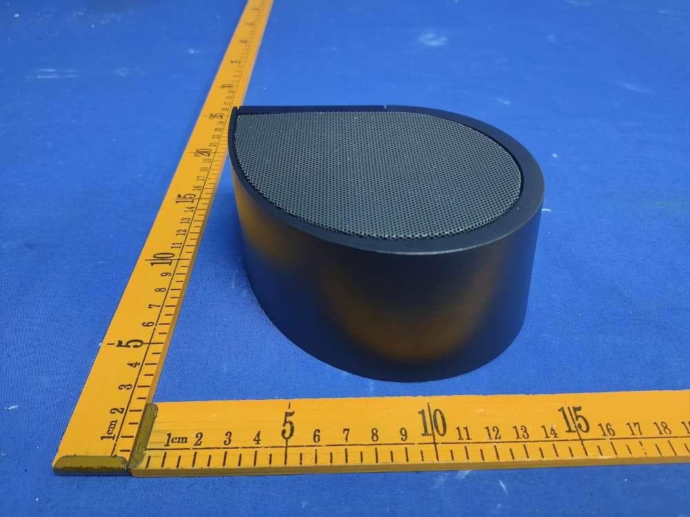
Click to zoom
Application Details
- Equipment Class
- DSS - Part 15 Spread Spectrum Transmitter
- Date of Grant
- Sep 25, 2023
- Application Purpose
- Original Equipment
- Date of Application
- Sep 25, 2023
- Equipment Note
- Aquarius
- Frequency Range
- 2402.00000000 - 2480.00000000
- Country
- United States
Documents & Files
Document Text
Text extracted from the exhibit documents filed with the FCC. Open a document above to read the original.
Users Manual
SOUND+SLEEP Aquarius Owner’s Manual - Getting Started - Product Features - Technical Reference - Warranty Information ©2023 Adaptive Sound Technologies, Inc. 2 To Our Customers, Thank you and congratulations on your purchase of the SOUND+SLEEP Aquarius from Adaptive Sound Technologies. You now own the highest quality, travel- friendly, non-looping, water sound sleep machine on the market today. Aquarius is unique, and the result of serious efforts by sleep, audio, electronics, and software specialists. Natural water sound ecosystems were captured with professional recording equipment and are reproduced in real-time using the latest in advanced electronics. Aquarius has six natural sound categories with three sound Richness selections in each for a total of 18 sleep sound options. All are sounds that have been on planet Earth for millions of years. This convenient product, with a compact yet rugged design, will provide you with a truly enjoyable listening experience whether you are sleeping, reading, or relaxing during travel or at home. You can also connect your Bluetooth headphones, earbuds, or speaker pillow, and stream music from your smartphone to the Aquarius speaker system. If you have any suggestions or ideas on how we can make our products better, please let us know. Sam J. Nicolino Jr. President and CEO, Adaptive Sound Technologies, Inc. Write down your Serial Number: Record your serial number here. Your serial number is printed on the bottom of the machine. Refer to these numbers whenever you contact ASTI regarding this product. Model Number: ASM1029 Name/Part Number: Serial Number: Date of Purchase: Protect your warranty: Please complete your warranty registration with your reseller using their recommended procedure. You can also register with ASTI at soundofsleep.com to protect your factory warranty. 3 Table Of Contents Getting Started ..........................................................................4 What Is Special About This Machine? ................................. 5 Richness Control .............................................................................. 5 Bluetooth Operation ......................................................................... 5 Aquarius Remote Control ................................................................ 6 Useful Features ........................................................................ 7 Sleep Timer ....................................................................................... 7 Panel Lights ...................................................................................... 7 Internal Rechargeable Battery ........................................................ 7 Sleep Sounds ................................................................................... 7 Specifications .................................................................................... 8 How to Restore Factory Settings .................................................... 8 Trouble Shooting .............................................................................. 8 Customer Support ............................................................................ 8 Appendix .................................................................................... 9 Using Aquarius with your Smartphone .......................................... 9 Using Aquarius with your Bluetooth Headphones ........................ 9 Turning Bluetooth Off ....................................................................... 9 Safety, Warranty, and Certifications .................................. 10 Safety Instructions .......................................................................... 10 One Year Limited Warranty .......................................................... 11 Software Licensing ........................................................................ 12 FCC Warnings ................................................................................ 12 IC Warnings .................................................................................... 13 Declaration...................................................................................... 14 Adaptive Sound Technologies, Inc. 4 Getting Started Unpack the box, which contains: 1. Aquarius Unit 2. AC Power Adapter & Power Cable 3. Remote Control 4. User Manual (this document) Connect Power by gently pushing the USB-C plug end of the Power Cable into the USB-C connector on the lower right edge of Aquarius (see above), then plug the larger USB-A end of the Power Cable into the supplied AC Power Adapter. Plug the Power Adapter into an un-switched wall outlet. The Aquarius USB-C connector only provides power to the Aquarius unit. Note: Aquarius can also be powered by the internal battery when AC power is not available. If you prefer, you can leave your Aquarius plugged in all the time. When the internal battery is charging the red charging light will be on. Turn on Aquarius by pressing the Power Button. The unit can be turned off immediately with the Power Button, or turned off gradually over time with the Sleep Timer (see page 6). Note: The unit starts in the ocean category with richness level 1 in that category selected. After that the unit will return to the settings used when you last powered it off using the power button or turned off using the Sleep Timer. Press The Center Button to select the desired sound category. Press the Richness Button to select the complexity of the sound (see page 5). Adjust the volume with the Volume Up/Down Buttons to a comfortable level. If you try to increase volume beyond the maximum level the Timer light will flash. Remote Control Power Button On/Off Richness Button (3 levels) Category Lights (6x: ocean, ...) Microphone Timer Button (1, 2 or 3 hours) IR sensor Volume Buttons Up & Down Charging Light (Near whales light) Category Button Bluetooth Button (3 modes) BT-off BT-in BT-out Headphone Jack USB-C Connector 5 What Is Special About This Machine?…
Text truncated - open the document above for the full version.
External Photos
FCCID:2AJGOASM1029 IC:21835-ASM1029 FCCID:2AJGOASM1029 IC:21835-ASM1029 FCCID:2AJGOASM1029 IC:21835-ASM1029 FCCID:2AJGOASM1029 IC:21835-ASM1029
Internal Photos
FCCID:2AJGOASM1029 IC:21835-ASM1029 FCCID:2AJGOASM1029 IC:21835-ASM1029 Ant FCCID:2AJGOASM1029 IC:21835-ASM1029
RF Exposure Info
RFExposureevaluation Exposurecategory:Generalpopulation/uncontrolledenvironment EUTType:ProductionUnit DeviceType:MobileDevice ReferStandard:KDB447498D01GeneralRFExposureGuidancev06 FCCPart2§2.1091 FCCID:2AJGOASM1029 1.Reference Accordingto§1.1307(b)(1),systemsoperatingundertheprovisionsofthissectionshallbe operatedinamannerthatensuresthatthepublicisnotexposedtoradiofrequencyenergy levelinexcessoftheCommission’sguidelines. Accordingto§1.1310and§2.1091RFexposureiscalculated. KDB447498D01:MobileandPortableDevicesRFExposureProceduresandEquipment AuthorizationPolicies 2.Limit LimitsforMaximumPermissibleExposure(MPE)/ControlledExposure Frequency Range(MHz) ElectricField Strength(V/m) MagneticField Strength(A/m) PowerDensity (mW/cm²) AveragingTime (minute) LimitsforOccupational/ControlledExposure 0.3–3.06141.63(100)*6 3.0–301842/f4.89/f(900/f 2 )*6 30–30061.40.1631.06 300–1500//f/3006 1500–100,000//56 LimitsforMaximumPermissibleExposure(MPE)/UncontrolledExposure Frequency Range(MHz) ElectricField Strength(V/m) MagneticField Strength(A/m) PowerDensity (mW/cm²) AveragingTime (minute) LimitsforOccupational/ControlledExposure 0.3–3.06141.63(100)*30 3.0–30824/f2.19/f(180/f 2 )*30 30–30027.50.0730.230 300–1500//f/150030 1500–100,000//1.030 F=frequencyinMHz *=Plane-waveequivalentpowerdensity 3.MPECalculationMethod PredicationofMPElimitatagivendistance Equationfrompage18ofOETBulletin65,Edition97-01 S=PG/4πR² Where:S=powerdensity P=powerinputtoantenna G=powergainoftheantennainthedirectionofinterestrelativetoanisotropicradiator R=distancetothecenterofradiationoftheantenna 4.Result AsdeclaredbytheApplicant,theEUTisawirelessdeviceusedinafixapplication,atleast 20cmfromanybodypartoftheuserornearbypersons;fromthemaximumEUTRFoutput power,theminimumseparationdistance,r=20cm,aswellasthegainoftheusedBTantenna is0dBi,theRFpowerdensitycanbeobtained. EDR Freq. (MHz) Output Power (dBm) Targetpower W/tolerance (dBm) Maxtuneup power tolerance (dBm) Outputpower toantenna (mW) Ant Gain (dBi) Power Densityat R=20cm (mW/cm2) Limit (mW/c m2) Result GFSK 2402 -4.933 -4±1.0-30.50100.000101Pass 2441 -4.820 -4±1.0-30.50100.000101Pass 2480 -5.090 -5±1.0-40.39800.000081Pass π/4DQPSK 2402 -4.213 -4±1.0-30.50100.000101Pass 2441 -4.018 -4±1.0-30.50100.000101Pass 2480 -4.265 -4±1.0-30.50100.000101Pass 8DPSK 2402 -3.616 -3±1.0-20.61300.000131Pass 2441 -3.480 -3±1.0-20.61300.000131Pass 2480 -3.693 -3±1.0-20.61300.000131Pass Note:Theestimationdistanceis20cm 5.Conclusion ThemeasurementresultscomplywiththeFCCLimitper47CFR2.1091fortheuncontrolled RFExposureofmobiledevice.
Test Report
Antenna Describe 1. Antenna Describe Antenna Plate PF Antenna Make Name/Model Name M2 of AC6905B Antenna Gain 0 DBI Frequency Range 2.402GHZ------2.480GHZ Connector Range Direct Location of Mearement(Company Name) ShenZhen RuiRongDa Electronic Co,LTD 2.External View Drawing: Picture of antenna 3. Antenna Radiation Pattern Radiation Pattern @ 2.402GHZ Total Average Gain: -0.475DBI Radiation Pattern @ 2.441GHZ Total Average Gain: -0.275DBI Radiation Pattern @ 2.480GHZ Total Average Gain: -0.237DBI
Test Report
Page 1 of 53 Hotline: 400-8868-419Fax: 86-755-27790922http://www.ncttesting.cn FCC Part 15C&RSS-247 TEST REPORT FCC ID:2AJGOASM1029 IC:21835-ASM1029 Product:Aquarius Model Name:ASM1029 Brand: Report No.:NCT23036039XE Prepared for Adaptive Sound Technologies Inc. 1475 South Bascom Ave, Ste 116; Campbell, CA 95008-0646, USA Prepared by Shenzhen NCT Testing Technology Co., Ltd. A101&2F B2, Fuqiao 6th Area, Xintian Community, Fuhai Street, Baoan District, Shenzhen, People’s Republic of China TEL: 400-8868-419 FAX: 86-755-27790922 ReportNo.:NCT23036039XE Page 2 of 53 Hotline: 400-8868-419Fax: 86-755-27790922http://www.ncttesting.cn 1 TEST RESULT CERTIFICATION Applicant’s name: Adaptive Sound Technologies Inc. Address: 1475 South Bascom Ave, Ste 116; Campbell, CA 95008-0646, USA Manufacture's name : Adaptive Sound Technologies Inc. Address : 1475 South Bascom Ave, Ste 116; Campbell, CA 95008-0646, USA Product name : Aquarius Model name : ASM1029 Additional model :N/A Standards : FCC CFR47 Part 15 Section 15.247 RSS-247 Issue 2: February 2017 Test procedure : ANSI C63.10:2013 RSS-GEN, Issue 5: March 2019 Test Date: Aug. 15, 2023 to Sep. 06, 2023 Date of Issue: Sep. 08, 2023 Test Result :Pass This device described above has been tested by NCT, and the test results show that the equipment under test (EUT) is in compliance with the FCC requirements. And it is applicable only to the tested sample identified in the report. This report shall not be reproduced except in full, without the written approval of NCT, this document may be altered or revised by NCT, personal only, and shall be noted in the revision of the document. Test Engineer: KevenWu/Engineer Technical Manager: Henry Wang / Manager ReportNo.:NCT23036039XE Page 3 of 53 Hotline: 400-8868-419Fax: 86-755-27790922http://www.ncttesting.cn Contents Page 1 TEST RESULT CERTIFICATION...............................................................................................................................2 2 TEST SUMMARY.......................................................................................................................................................... 5 3 TEST FACILITY.............................................................................................................................................................6 4 GENERAL INFORMATION..........................................................................................................................................7 4.1 G ENERALDESCRIPTION OFE.U.T.....................................................................................................................7 4.2 C HANNELLIST..................................................................................................................................................... 8 4.3 T ESTSETUPCONFIGURATION............................................................................................................................9 4.4 T ESTMODE......................................................................................................................................................... 9 5 EQUIPMENT DURING TEST.................................................................................................................................... 10 5.1 E QUIPMENTSLIST............................................................................................................................................. 10 5.2 M EASUREMENTUNCERTAINTY......................................................................................................................... 12 5.3 D ESCRIPTION OFSUPPORTUNITS...................................................................................................................12 6 CONDUCTED EMISSION.......................................................................................................................................... 13 6.1 E.U.T. O PERATION............................................................................................................................................13 6.2 EUT S ETUP....................................................................................................................................................... 13 6.3 T ESTSET-UP (BLOCKDIAGRAM OFCONFIGURATION)................................................................................. 14 6.4 M EASUREMENTPROCEDURE:...........................................................................................................................14 6.5 C ONDUCTEDEMISSIONLIMIT........................................................................................................................... 14 6.6 M EASUREMENTDESCRIPTION.......................................................................................................................... 14 6.7 C ONDUCTEDEMISSIONTESTRESULT.............................................................................................................14 7 RADIATED SPURIOUS EMISSIONS...................................................................................................................... 17 7.1 EUT O PERATION...............................................................................................................................................17 7.2 T ESTSETUP...................................................................................................................................................... 18 7.3 S PECTRUMANALYZERSETUP.......................................................................................................................... 19 7.4 T ESTPROCEDURE.............................................................................................................................................20 7.5 S UMMARY OFTESTRESULTS...........................................................................................................................21 8 MAXIMUM PEAK OUTPUT POWER TEST....................................…
Text truncated - open the document above for the full version.
Test Setup Photos
FCCID:2AJGOASM1029 IC:21835-ASM1029 RadiatedEmission (Below1G) RadiatedEmission (Above1G) ConductedEmission
Contact Information
Applicant
Sam Nicolino(President & CEO)
Technical Contact
Test Firm
SHENZHEN NCT TESTING TECHNOLOGY CO., LTD.Henry Wang
[email protected]0755-27790922
Technical Specifications
| # | Rule Parts | Frequency Range | Power Output |
|---|---|---|---|
| 1 | 15C | 2.40 GHz - 2.48 GHz | 400.00 µW |