2AJOATX2065ARC Weather Station with Colorful Display
AOK Electronic Limited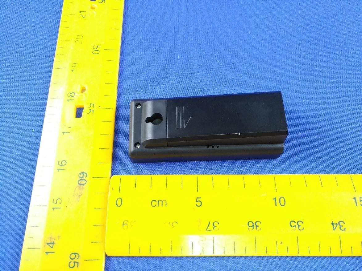
Click to zoom
Application Details
- Equipment Class
- DXX - Part 15 Low Power Communication Device Transmitter
- Date of Grant
- Jun 11, 2022
- Application Purpose
- Original Equipment
- Date of Application
- Jun 09, 2022
- Equipment Note
- RC Weather Station with Colorful Display
- Frequency Range
- 433.92000000 - 433.92000000
- Company
- AOK Electronic Limited
- Country
- China
Documents & Files
Document Text
Text extracted from the exhibit documents filed with the FCC. Open a document above to read the original.
Users Manual
3 Package included: • Weather station x 1 • Wireless sensor x 1 • 2 batteries - LR6 type (AA) / 1.5 V(base unit) • 2 batteries - LR03 type (AAA) / 1.5 V(wireless sensor) • 2 x screws and dowels • Operating instruction Product functions Weather station • 12- or 24-hour display • Date, time and day of week in 8 language • Dual alarm with snooze function • Indoor temperature display in°C/°F • Indoor and outdoor humidity display • Outdoor temperature display in°C/°F with up to three wireless sensors at different measurement sites (delivery includes one wireless sensor) • Minimum/maximum display for temperature and humidity • Humidity and temperature trend display • Weather forecast symbols • Moon phase display • Comfort indicator • Low battery indicator 4 Wireless sensor • Temperature display in°C/°F • Humidity display in % • Range of up to 328 ft (100 meters) (in open area) • Low battery indicator • Wall mounting bracket Overview of weather station 1.Upper/Lower limit symbol 2.Automatic switching symbol 3.Outdoor 4.Current channel of outdoor sensor 5.Outdoor temperature trend 6. Outdoor temperature 7. Outdoor humidity trend 8. Maximum outdoor temperature 5 9. Outdoor humidity 10. Maximum outdoor humidity 11. Low battery indicator for outdoor 12. Maximum indoor temperature 13. Maximum indoor humidity 14. Low battery indicator for indoor 15. Indoor humidity 16. Indoor humidity trend 17. DST symbol 18. Radio control indicator 19. Time display 20. Alarm symbol 21. Day of week 22. Month 23. Date 24. Moon phase 25. Indoor temperature trend 26. Indoor temperature 27. Comfort indicator 28. Indoor symbol 29. Air pressure trend 1Temperature display 2Radio frequency display 6 3Current transmission channel 4Humidity display 5Low battery indicator 6Red pilot light 7Switch°C/°F 8TX button 9Loop for hanging 10 Sliding switch 1 2 3: Set sensor number (transmission channel) 11 Battery compartment cover How to set up Insert batteries 1.Insert 2 x AAA batteries into the wireless sensor. Pay attention to the correct polarity. While the sensor is transmitting, the red LED indicator will flash. 2.Open the battery compartment of the weather station and insert 2 x AA batteries in the correct polarity. Close the battery compartment. Setting the weather symbol When the weather station is connected to the adapter or batteries on the first time, it will enter it will enter the 7-level weather adjustment mode. You will see the weather symbol starts flashing, and the default is half cloudy. It will automatically adjust to the correct symbol. However, if you want to shorten the reception time of the weather station, you can manually adjust it through andbutton. 6.Press theSNOOZE/LIGHT button to save the setting. 7.To re-adjust, long press theSNOOZE/LIGHT button at the top till the weather symbol start to flash. Pairing the outdoor sensor with the weather station 7 When the weather station is connected to the batteries on the first time, after detecting the temperature/humidity, it will automatically enter the weather setting mode, press the Snooze button to exit or automatically exit after 20S, enter the RF receiving for 3 minutes, and then enter the receiving RCC for 7 minutes. Generally, the outdoor sensor will connect with the base unit automatically. If it doesn’t connect, please follow below steps to set: • Ensure that the weather station is in the same channels with the outdoor sensor. • Long press theCH button on the base unit to search signal from the outdoor sensor. • The sensor receiving icon will flash when searching for the signal. • After the sensor is connected, the icon will become stable. Note: After replacing the sensor battery, you need to press and hold the CH button of the station to receive again. Reception RCC After successful reception of the signal for the outdoor sensor, the reception of the DCF77 time signal will begin and the radio control indicator will blink on the display next to the time. This process can take from 7 minutes. All buttons except theSNOOZE/LIGHTand buttons are disabled during the reception process. When the signal is received, the RCC tower part mark is static, and the arc antenna flashes at a frequency of 1Hz; When the signal is weak and the correct signal cannot be distinguished, the tower part flashes at 1Hz, and the arc antenna part does not display. 1.When the receiving signal is successful, the RCC receiving sign will be fully displayed and the receiving state will be exited; 2. During the receiving process, single pressing the "" button will exit the RCC receiving state, except that single pressing the "SNOOZE/LIGHT" button can light up the backlight function, other buttons have no function; 3. Automatic reception: every morning (current time zone)01:00, 02:00, 03:00 to force reception to 04:00, 05:00 to choose to receive 05:00, regardless of whether the reception is successful or not, it will no longer be received on that day, and the RCC reception time is 7 minutes; 4. If the receiving signal fails on the same day, the next receiving time will be 01:00 the next day; 5. In the process of receiving RCC, when encountering the ALARM alarm, it will exit the RCC reception and switch to the alarm 8 6. When DST signal is received, DST logo will be displayed on LCD; 7.When the RCC symbol and DST are displayed, after resetting the time, the RCC symbol and DST will disappear; 8. Adapter power supply: The backlight is automatically turned off when RCC is receiving, and the original lighting state is automatically restored after receiving. Setting the basic data • Press and hold theSET button for 3 seconds till the year starts flashing, now you are in the basic settings. • To adjust the data through andbutton. • Then press theSETbutton to confirm and jump to the next setting. Below are the setting orders: 1.MD/DM 2.Month 3.Date 4.Time zone 5.Hour 6.Minutes 7.12H/24H 8.Language 9.RCC ON/OFF(default ON) Setting the alarm There are dual alarms on the weather station. You can set the…
Text truncated - open the document above for the full version.
External Photos
Appendix Model: AOLD-2065A Appendix Model: AOLD-2065A Appendix Model: AOLD-2065A
ID Label/Location Info
Unit Size:102x43.5x29.5mm LCD VA: 22x10mm FCC ID: 2AJOATX2065A 34.00 mm 5.00 mm
Internal Photos
Appendix Model: AOLD-2065A Appendix Model: AOLD-2065A Appendix Model: AOLD-2065A Antenna Oscillator Appendix Model: AOLD-2065A Oscillator
RF Exposure Info
Report Number: 60.790.22.017.01R01 TÜV SÜD Certification and Testing (China) Co., Ltd. Shenzhen Branch Building 12&13, Zhiheng Wisdomland Business Park, Nantou Checkpoint Road 2, Nanshan District, 518052 Shenzhen, CHINA Page 23 of 24 Radiofrequency radiation exposure evaluation This exposure evaluation is intended forFCC ID: 2AJOATX2065A According to FCC CFR 47 part1 1.1310, As specified in Table 1B of 47 CFR 1.1310 – Limits for Maximum Permissible Exposure (MPE), Limits for General Population/Uncontrolled Exposure Frequency range (MHz) Electric field strength (V/m) Magnetic field strength (A/m) Power density (mW/cm 2 ) Averaging time (minutes) (B) Limits for General Population/Uncontrolled Exposure 0.3-1.346141.63*10030 1.34-30824/f2.19/f*180/f 2 30 30-30027.50.0730.230 300-1,500f/150030 1,500-100,0001.030 MPE calculation method: Pd = (P*G) / (4*Pi* R 2 ), where Pd = power density in mW/cm 2 P = output power to antenna in mW G = gain of antenna in linear scale Pi = 3.1416 R= calculation distance in cm >> The limit of Power density 433.92MHz is 433.92 /1500=0.29mW/cm 2 >> The antenna gain is 0dBi (=1 in linear scale). Manufacturer specified the separation distance is: 20cm The max. power (calculated power + tune up tolerance) of EUT at 433.92MHz is: 0.0098mW >> The Pd calculated of 433.92MHz is 0.000002mW/cm 2 Which is smaller than the threshold of the limit. Therefore, the device is exempt from stand-alone SAR test requirements. 10 Appendix A-General Product Information Report Number: 60.790.22.017.01R01 TÜV SÜD Certification and Testing (China) Co., Ltd. Shenzhen Branch Building 12&13, Zhiheng Wisdomland Business Park, Nantou Checkpoint Road 2, Nanshan District, 518052 Shenzhen, CHINA Page 24 of 24 Power calculation (According to C63.10 chapter 9.5) 433.920MHz Field Strength Measured (E)75.09dBμV/m Measurement Distance (D)3m Equivalent Isotropically Radiated Power (E.I.R.P in dBm)-20.07dBm Equivalent Isotropically Radiated Power (E.I.R.P in mW)0.0098mW Remark: EIRP = E + 20log(D) −104.7 (EIRP is in dBm, E is indBμV/m, D is in metres) Reviewed by: Prepared by: ______________________ ___________________ Eric LIHosea CHAN EMCProject ManagerEMC Project Engineer
Test Report
Report Number: 60.790.22.017.01R01 TÜV SÜD Certification and Testing (China) Co., Ltd. Shenzhen Branch Building 12&13, Zhiheng Wisdomland Business Park, Nantou Checkpoint Road 2, Nanshan District, 518052 Shenzhen, CHINA Page 1 of 24 FCC - TEST REPORT Report Number:60.790.22.017.01R01Date of Issue:May 24, 2022 Model:AOLD-2065A Product Type:RCWeather Stationwith Colorful Display (Transmitter Unit) Applicant:AOK ELECTRONIC LIMITED Address:Tianxin Industrial District, Dahou Village, Xiegang Town, Dongguan City, Guangdong Province, China Production Facility :AOLD ELECTRONIC LIMITED Address:Tianxin Industrial District, Dahou Village, Xiegang Town 523599 Dongguan City,Guangdong Province PEOPLE'S REPUBLIC OF CHINA Test Result:nPositiveoNegative Total pages including Appendices : 24 TÜV SÜD Certification and Testing (China) Co., Ltd. Shenzhen Branch is a subcontractor to TÜV SÜD Product Service GmbH according to the principles outlined in ISO 17025. TÜV SÜD Certification and Testing (China) Co., Ltd. Shenzhen Branch reports apply only to the specific samples tested under stated test conditions. Construction of the actual test samples has been documented. It is the manufacturer's responsibility to assure that additional production units of this model are manufactured with identical electrical and mechanical components. The manufacturer/importer is responsible to the Competent Authorities in Europe for any modifications made to the production units which result in non-compliance to the relevant regulations. TÜV SÜD Certification and Testing (China) Co., Ltd. Shenzhen Branch shall have no liability for any deductions, inferences or generalizations drawn by the client or others from TÜV SÜD Certification and Testing (China) Co., Ltd. Shenzhen Branch issued reports. This report is the confidential property of the client. As a mutual protection to our clients, the public and ourselves, extracts from the test report shall not be reproduced except in full without our written approval Report Number: 60.790.22.017.01R01 TÜV SÜD Certification and Testing (China) Co., Ltd. Shenzhen Branch Building 12&13, Zhiheng Wisdomland Business Park, Nantou Checkpoint Road 2, Nanshan District, 518052 Shenzhen, CHINA Page 2 of 24 1 Table of Contents 1 Table of Contents ............................................................................................................ 2 2 Description of Equipment Under Test ............................................................................. 3 3 Summary of Test Standards ........................................................................................... 4 4 Details about the Test Laboratory ................................................................................... 5 4.1 Test Equipment Site List ................................................................................................... 6 4.2 Measurement System Uncertainty .................................................................................... 7 5 Summary of Test Results ................................................................................................ 8 6 General Remarks ............................................................................................................ 9 7 Test Setups ................................................................................................................... 10 7.1 Radiated test setups 9kHz-30MHz .................................................................................. 10 7.2 Radiated test setups Below 1GHz................................................................................... 10 7.3 Radiated test setups Above 1GHz .................................................................................. 10 7.4 AC Power Line Conducted Emission test setups ............................................................ 11 7.5 Conducted RF test setups............................................................................................... 11 8 Emission Test Results .................................................................................................. 12 8.1 Spurious Radiated Emission ........................................................................................... 12 8.2 20dB Bandwidth .............................................................................................................. 16 8.3 Transmission Time.......................................................................................................... 17 9 Test setup procedure .................................................................................................... 19 10 Appendix A - General Product Information ................................................................. 23 Report Number: 60.790.22.017.01R01 TÜV SÜD Certification and Testing (China) Co., Ltd. Shenzhen Branch Building 12&13, Zhiheng Wisdomland Business Park, Nantou Checkpoint Road 2, Nanshan District, 518052 Shenzhen, CHINA Page 3 of 24 2 Description of Equipment Under Test Description of the Equipment Under Test Product: RC Weather Station with Colorful Display (Transmitter Unit) Model no.:AOLD-2065A FCC ID:2AJOATX2065A Rating:3 VDC (2 x 1.5V AAA battery) Frequency:433.920MHz Antenna gain:0 dBi Number of operated channel:1 Modulation:ASK Auxiliary Equipment Used during Test: DESCRIPTION MANUFACTURER MODEL NO.(SHIELD) S/N(LENGTH) -------- Report Number: 60.790.22.017.01R01 TÜV SÜD Certification and Testing (China) Co., Ltd. Shenzhen Branch Building 12&13, Zhiheng Wisdomland Business Park, Nantou Checkpoint Road 2, Nanshan District, 518052 Shenzhen, CHINA Page 4 of 24 3 Summary of Test Standards Test Standards FCC Part 15 Subpart C 10-1-20 Edition Federal Communications Commission, PART 15 — Radio Frequency Devices, SubpartC—Unintentional Radiators Report Number: 60.790.22.017.01R01 TÜV SÜD Certification and Testing (China) Co., Ltd. Shenzhen Branch Building 12&13, Zhiheng Wisdomland Business Park, Nantou Checkpoint Road 2, Nanshan Dis…
Text truncated - open the document above for the full version.
Test Setup Photos
Appendix Model: AOLD-2065A Radiated Emission Test below 1 GHz Radiated Emission Test above 1 GHz
Contact Information
Applicant
Banden Shi(General Manager)
Test Firm
TUV SUD Cert & Testing (China) Co., Ltd.Harry Zhou
[email protected]86 755 3332 3281
Technical Specifications
| # | Rule Parts | Frequency Range | Power Output |
|---|---|---|---|
| 1 | 15C | 433.92 MHz - 433.92 MHz | - |