2AJONSEED-10IA-555.5 Generation Intelligent Screen
Shanghai Rising Digital Co.,Ltd.
Click to zoom
Application Details
- Equipment Class
- PCB - PCS Licensed Transmitter
- Date of Grant
- Apr 15, 2020
- Application Purpose
- Original Equipment
- Date of Application
- Apr 15, 2020
- Equipment Note
- 5.5 Generation Intelligent Screen
- Frequency Range
- 2506.00000000 - 2680.00000000
- Country
- China
Documents & Files
Document Text
Text extracted from the exhibit documents filed with the FCC. Open a document above to read the original.
Users Manual
SEED-10IA-55 User Manual | Shanghai Rising Digital Co.,Ltd. Display Screen SEED-10IA-55 User Manual SEED-10IA-55 User Manual | Shanghai Rising Digital Co.,Ltd. General introduction As an on‐board display screen, SEED-10IA-55 can meet the needs of human‐computer interaction, network connection, data storage, multimedia audio‐visual entertainment under adverse working conditions such as construction machinery and special machinery. In the engineering automation situation, IPC can be replaced as monitoring station equipment. High‐Performance:Dual Core Processor, 800MHz, 1G Memory, 8G Hard Disk Universality: Intelligent Operating System, Configuration Software Beautiful shape: flat panel, capacitive touch screen; antenna built‐in Wireless Networking: GPRS/4G, BT, GPS SEED-10IA-55 User Manual | Shanghai Rising Digital Co.,Ltd. Catalog Functions and Characteristics ..................................................................................................1 1、 Integration of Display and Communication ............................................................... 1 2、 General Configuration Program Development Environment .................................... 1 3、 Adapt to harsh environment ...................................................................................... 1 4、 Seamless connection of remote monitoring system ................................................. 1 Functional description of External interface ........................................................................... 1 1、 External characteristics ............................................................................................. 1 2、 Port Definition of 34 Pin Plug‐in ............................................................................... 2 Development and debugging ................................................................................................... 3 1、 Hardware platform .................................................................................................... 3 2、 Software Development Platform .............................................................................. 3 3、 Program burning ........................................................................................................4 Installation wiring ..................................................................................................................... 5 1、 Installation dimension ............................................................................................... 5 2、 Installation mode ....................................................................................................... 5 Description of product parameters and environmental indicators ........................................ 6 SEED-10IA-55 User Manual 1 | Shanghai Rising Digital Co.,Ltd. Functions and Characteristics 1、Integration of Display and Communication Display:10.4 inch, 1024 x 768 resolution, industrial TFT LCD screen, capacitive touch Com munication:Supporting 4G/GPRS/BT wireless communication, Support GPS/BD positioning, Supporting CAN comm un ication,compatibleJ1939 / CAN Ope n / CAN 2. 0B agreement Ca mera: Supports 4 analog cam eras, single, 2-partition, 4-p art iti on display 2、General Configuration Program Development Environment General Configuration Software Based on Intelligent Operating System。 3、Adapt to harsh environment Can be used in severe cold and hot environment: - 25 degrees low temperature, 65 degrees high temperature Power supply anti-backconnection design, greater than 37V self-protection, prevent burnout Suitable f or st ron g vibration, dust, rainwater, lig htning and othe r environment in f ield operation 4、Can access EVI App to realize remote monitoring Supporting remote unlocking machine to facilitate creditor's rights management Access to EVI App to achieve remote monitoring Functional description of external interface 1、 External characteristics SEED-10IA-55 User Manual 2 | Shanghai Rising Digital Co.,Ltd. 2、 Port Definition of 34 Pin Plug‐in port number Function definition 1 CAN2_H 2 NC 3 SET 4 +12VOUT 5 CAN1_L 6 CAN1_H 7 CAMRA2_V‐ 8 GND 9 +5V OUT 10 CAN2_L 11 NC 12 +12VOUT 13CAMRA1_V+ 14CAMRA1_V‐ 15CAMRA2_V+ 16CAMRA3_V‐ 17SMI 18 NC 19 NC 20 NC 21 CAMRA4_V+ SEED-10IA-55 User Manual 3 | Shanghai Rising Digital Co.,Ltd. 22 CAMRA4_V‐ 23 CAMRA3_V+ 24 GND 25 24V in 26 NC 27 TX232 28 RX232 29 RS485_A 30 RS485_B 31 NC 32NC 33GND 34+24V in Development and Debugging 1、 Hardware platform The conf iguration development software QT is installed on the PC. The power supply and camera are connected to the display screen, and the platform is built. 2、Software Development Platform SEED-10IA-55 User Manual 4 | Shanghai Rising Digital Co.,Ltd. Supporting configuration software, using standard IDE development environment, can develop applications according to project requirements. You can refer to the commonly used sample programs to develop applications quickly. Include: 1) QuickStart Human-Machine Interface, including Common Man-Machine Operating Controls 2 ) Communication function library, including CAN/4G/GPS 3) Camera display demo, supporting 4‐partition and 2‐partition display 3、 Procedure burning 3.1 Configuration program burning 1)Set up app folder under U disk root directory and place application configuration program 2)The U disk is connected to the USB port behind the display screen. Electricity on the motherboard, pop‐up configuration selection of the display screen, click "burn", the U‐disk indicator lights start flashing, and show the progress of burning.。 4) After burning, the display will restart automatically without power cut. 3.2 Kernel and Device Tree Burning 1)Connecting devices and notebooks via Ethernet 2)Close Firewall of Laptop Windows System。 3)Setting up IP (display IP) and server IP (computer IP) mus t be in the same network segment (1)Setting up Computer IP:192.168.1.66 (2)Setting up display IP:192.168.1.62.No modification by default (3)Display reboot i…
Text truncated - open the document above for the full version.
Attestation Statements
Company: Shanghai Rising Digital Co.,Ltd. Add: No 318 ,Chuanda Road , Pudong New District Shanghai China Tel: +86 0512 57831258 Fax: +86 0512 57831258 Attestation Letter Date:2019-10-11 Dear Sir/Madam, The product 5.5 Generation Intelligent Screen,model:SEED-10IA-55(G), FCC ID: 2AJONSEED-10IA-55 uses module EG25-G which can support LTE FDD/TDD, WCDMA, GSM functions. But this product only activates LTE band 5/41 and GPRS/EGPRS 850/1900,the other bands and functions have been shielded by the manufactures using the software . Sincerely, Signature: Typed or Printed Name: Xin Yan Title: manager
Cover Letter(s)
QA-FR-170-B Company: Shanghai Rising Digital Co.,Ltd. Add: No 318, Chuanda Road, Pudong New District, Shanghai, China Tel: +86 0512 57831258 Fax: +86 0512 57831258 FCC Authorization Date: 2019-10-11 FE DERAL COMM UNICATIONS COMMISSION Authorization and Evaluation Division 7435 Oakland Mills Road Columbia, MD 21046 Subject: Agent Authorization To whom it may concern: We, Shanghai Rising Digital Co.,Ltd., the undersigned, Hereby authorizes Bay Area Compliance Laboratories Corporation to act on its behalf in all matters relating to application for Equipment authorization, including the signing of all documents relating to these matters. All acts carried out by Bay Area Compliance Lab oratories Corp. on our behalf shall have the same effect as our own action. We, the undersigned, hereby certify that we are not subject to a denial of federal benefits, that includes FCC benefits, pursuant to Section 5301 of the Anti-Drug Abuse Act of 1988, 21 U.S.C. 862. This authorization is valid until further written notice from the applicant. Sincerely Yours, Signature: Typed or Printed Name: Xin Yan Title: manager
Cover Letter(s)
QA-FR-171-A FCC Confidential Auth orization 2019-10-11 FEDERAL COMMUNICATIONS COMMISSIONS Authorization and Evaluation Division 7435 Oakland Mills Road Columbia, MD 21046 Subject: Confidentiality Request regarding application for certification of FCC ID: 2AJONSEED-10IA-55 In accordance with Sections 0.457 and 0.459 of the Commission’s Rules, Shanghai Rising Digital Co.,Ltd. hereby requests long-term confidential treatment of information accompanying this application as outlined below: •Block Diagram •Schematics •Operation Description •Bom The above materials contain proprietary and confidential information not customarily released to the public. The public disclosure of these materials provides unjustified benefits to its competitors in the market. Sincerely, Signature: Typed or Printed Name: Xin Yan Title: manager Company: Shanghai Rising Digital Co.,Ltd. Add: No 318, Chuanda Road, Pudong New District, Shanghai, China Tel: +86 0512 57831258 Fax: +86 0512 57831258 E-mail: [email protected] • Tune up Procedure
External Photos
EXHIBIT A - EUT EXTERNAL PHOTOGRAPHS GPRS&EGPRS<E Antenna GPRS&EGPRS<E Antenna port FM Antennaport
ID Label/Location Info
Product Name: 5.5 Generation Intelligent Screen Model: SEED-10IA-55 Input: 12-24VDC 2A FCC ID: 2AJONSEED-10IA-55 Shanghai Rising Digital Co.,Ltd. Add: No 318 ,Chuanda Road , Pudong New District Shanghai China
Internal Photos
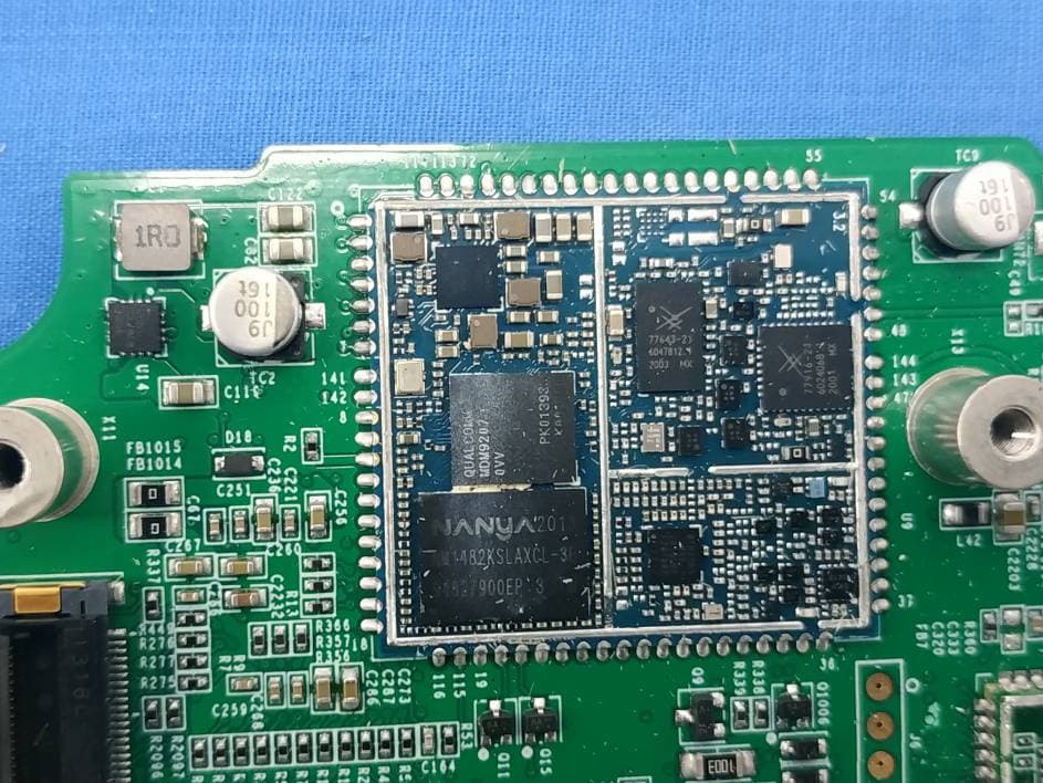
EXHIBIT B - EUT INTERNAL PHOTOGRAPHS BLE Antenna FM Antenna port GPRS&EGPRS& LTE Antenna port GPS Antenna
RF Exposure Info
Bay Area Compliance Laboratories Corp.( Kunshan) Report No.: RSHA191011002-00B FCC Part 22H, Part 24E, Part 27 Page 12 of 92 FCC §1.1310 & §2.1091- MAXIMUM PERMISSIBLE EXPOSURE (MPE) Applicable Standard According to subpart 1.1310, 2.1091 systems operating under the provisions of this section shall be operated in a manner that ensures the public is not exposed to RF energy level in excess of the communication guidelines. Limits for General Population/Uncontrolled Exposure Frequency Range (MHz) Electric Field Strength (V/m) Magnetic Field Strength (A/m) Power Density (mW/cm 2 ) Averaging Time (minutes) 0.3-1.34 614 1.63 *(100) 30 1.34-30 824/f 2.19/f *(180/f²) 30 30-300 27.5 0.073 0.2 30 300-1500 / f/1500 30 1500-100,000 / 1.0 30 f = frequency in MHz; * = Plane-wave equivalent power density Calculated Formulary: Predication of MPE limit at a given distance S = PG/4πR² = power density (in appropriate units, e.g. mW/cm 2 ); P = power input to the antenna (in appropriate units, e.g., mW); G = power gain of the antenna in the direction of interest relative to an isotropic radiator, the power gain factor, is normally numeric gain; R = distance to the center of radiation of the antenna (appropriate units, e.g., cm); For simultaneously transmit system, the calculated power density should comply with: Bay Area Compliance Laboratories Corp.( Kunshan) Report No.: RSHA191011002-00B FCC Part 22H, Part 24E, Part 27 Page 13 of 92 Calculated Data: Mode Frequency Range (MHz) Antenna Gain Tune-up Output Power Evaluation Distance (cm) Power Density (mW/cm 2 ) MPE Limit (mW/cm 2 ) (dBi) (numeric)(dBm)(mW) BLE 2402-2480 1.0 1.26 6.50 4.47 20 0.0011 1.00 GPRS/EGPRS 850 824.2-848.8 0.6 1.15 27.00501.1920 0.1145 0.55 GPRS/EGPRS 1900 1850.2-1909.8 0.6 1.15 23.50223.8720 0.0512 1.00 LTE Band 5 824.2-848.8 0.6 1.15 22.50177.8320 0.0406 0.55 LTE Band 41 2498.5-2687.5 3.7 2.34 23.50223.8720 0.1045 1.00 Note: GPRS 850: Tune-up maximum output power with 4 slot is 30.00 dBm, so the tune-up time based Ave. power compared to sloted Ave. power is 27.00 dBm. GPRS 1900: Tune-up Maximum output power with 4 slot is 26.50 dBm, so the tune-up time based Ave. power compared to sloted Ave. power is 23.50 dBm. EGPRS 850: Tune-up maximum output power with 4 slot is 26.00 dBm, so the tune-up time based Ave. power compared to sloted Ave. power is 23.00 dBm. EGPRS 1900: Tune-up Maximum output power with 4 slot is 23.00 dBm, so the tune-up time based Ave. power compared to sloted Ave. power is 20.00 dBm. Number of Time slot 1 2 3 4 Duty Cycle 1:8 1:4 1:2.66 1:2 Time based Ave. power compared to slotted Ave. power -9 dB -6 dB -4.26 dB -3 dB Note: GPRS/EGPRS/LTE and BLE can transmit simultaneously; the worst condition is below: =0.1145/0.55+0.0011/1.00=0.2093< 1.0 Result: The device meet FCC MPE at 20 cm distance.
Test Report
Note: This test report is prepared for the customer shown above and for the device described herein. It may not be duplicated or used in part without prior written consent from Bay Area Compliance Laboratories Corp. This report is valid only with a valid digital signature. The digital signature may be available only under the Adobe software above version 7.0. FCC PART 22H, PART 24E, PART 27 TEST REPORT For Shanghai Rising Digital Co.,Ltd. No 318, Chuanda Road, Pudong New District, Shanghai, China FCC ID: 2AJONSEED-10IA-55 Report Type: Original Report Product Type: 5.5 Generation Intelligent Screen Test Engineer: Sam Ye Re port Number: RSHA191011002-00B Re port Date: 2020-03-24 Reviewed B y: Oscar Ye EMC Manager Prepared By: Bay Area Compliance Laboratories Corp. (Kunshan) No.248 Chenghu Road, Kunshan, Jiangsu province, China Tel: +86-0512-86175000 Fax: +86-0512-88934268 www.baclcorp.com.cn Bay Area Compliance Laboratories Corp.( Kunshan) Report No.: RSHA191011002-00B FCC Part 22H, Part 24E, Part 27 Page 2 of 92 TABLE OF CONTENTS GENERAL INFORMATION ....................................................................................................................................... 3 PRODUCT DESCRIPTION FOR EQUIPMENT UNDER TEST (EUT) ..................................................................................... 3 OBJECTIVE ................................................................................................................................................................... 3 RELATED SUBMITTAL(S)/GRANT(S) ............................................................................................................................. 3 TEST METHODOLOGY .................................................................................................................................................. 3 MEASUREMENT UNCERTAINTY .................................................................................................................................... 4 TEST FACILITY ............................................................................................................................................................. 4 SYSTEM TEST CONFIGURATION .......................................................................................................................... 5 JUSTIFICATION ............................................................................................................................................................. 5 CHANNEL LIST ............................................................................................................................................................. 5 EQUIPMENT MODIFICATIONS ....................................................................................................................................... 6 SUPPORT EQUIPMENT LIST AND DETAILS .................................................................................................................... 6 EXTERNAL I/O CABLE .................................................................................................................................................. 6 BLOCK DIAGRAM OF TEST SETUP ................................................................................................................................ 7 SUMMARY OF TEST RESULTS ............................................................................................................................... 9 TEST EQUIPMENT LIST ......................................................................................................................................... 10 FCC §1.1310 & §2.1091- MAXIMUM PERMISSIBLE EXPOSURE (MPE) ............................................................ 12 APPLICABLE STANDARD ............................................................................................................................................ 12 CALCULATED FORMULARY: ....................................................................................................................................... 12 CALCULATED DATA: .................................................................................................................................................. 13 FCC §2.1047 - MODULATION CHARACTERISTIC ............................................................................................ 14 FCC §2.1046; § 22.913 (A); § 24.232 (C) ;§27.50 (H)- RF OUTPUT POWER ...................................................... 15 APPLICABLE STANDARDS........................................................................................................................................... 15 TEST PROCEDURE ...................................................................................................................................................... 15 TEST DATA ................................................................................................................................................................ 16 FCC §2.1049, §22.917, §22.905 , §24.238&§27.53 - OCCUPIED BANDWIDTH .................................................. 26 APPLICABLE STANDARDS........................................................................................................................................... 26 TEST PROCEDURE ...................................................................................................................................................... 26 TEST DATA ................................................................................................................................................................ 26 FCC § 2.1051; § 22.917 (A); § 24.238 (A) & §27.53 (M)- SPURIOUS EMISSIONS AT ANTENNA TERMINALS ............................................................................................................................................................... 40 APPLICABLE STANDARDS................................................................................…
Text truncated - open the document above for the full version.
Contact Information
Applicant
Xin Yan(manger)
Test Firm
Bay Area Compliance Laboratories Corp. (Kunshan)Mr. John Chan
[email protected]+86 0512 86175000
Technical Specifications
| # | Rule Parts | Frequency Range | Power Output | Emission | Tolerance |
|---|---|---|---|---|---|
| 14 | 27 | 2.51 GHz - 2.68 GHz | 77.00 mW | 18M0D7W | 2.5 ppm |
Other Applications from Shanghai Rising Digital Co.,Ltd.
2AJONSEED7I0A55
Nov 05, 20205.5 Generation Intelligent Screen
Equipment Class
DTS - Digital Transmission System
2AJONSERM012A
Sep 13, 2020Remote Control
Equipment Class
DSC - Part 15 Security/Remote Control Transmitter