2AJTV-W60X212Audio ChatPad
Dashine electronics co., Ltd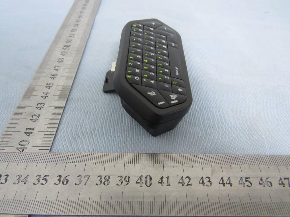
Click to zoom
Application Details
- Equipment Class
- DXX - Part 15 Low Power Communication Device Transmitter
- Date of Grant
- Apr 14, 2020
- Application Purpose
- Original Equipment
- Date of Application
- Apr 14, 2020
- Equipment Note
- Audio ChatPad
- Frequency Range
- 2412.00000000 - 2475.00000000
- Company
- Dashine electronics co., Ltd
- Country
- China
Documents & Files
Document Text
Text extracted from the exhibit documents filed with the FCC. Open a document above to read the original.
Users Manual
90mm 128mm Audio Chatpad USER MANUAL Xbox One™ X / S & Elite For use with EN Package Contents: • Wireless Chatpad x 1 • Wireless Dongle x 1 • User Manual x 1 3.5mm Audio Connector Keyboard To rectangular expansion port (Connect to Xbox One Controller Audio Port)(Connect to Xbox One Controller) 3.5mm Audio Port LED ON/OFF Wireless Dongle Foldable Audio Connector Specification: 2.4G wireless keyboard easily connects to the Xbox One Console Enables most wired stereo headsets to work with your Xbox One Controller . Easily adjust audio without taking your hands off the controller. Controls include volume up/down, microphone mute, and speaker mute. Connects to the bottom of the Xbox One Wireless Controlle r and features a 3.5mm audio jack for your wired headset to plug into. Microphone mute, and speaker mute LED indication. Powered by the controller . • • • • • • • Setting up the Chatpad: Following this illustration, line up the connector of the chatpad with the rectangular expansion port at the bottom o f the Xbox One Controller. 1. Removal from the Xbox One Controlle r: Please following this illustration carefully: Gently lift the bottom of the Chatpad in the direction shown (up). 1. While lift ing up, gently pull the chatpad out from the Xbox One controller at the same time. 2. Carefully insert the expansion port and 3.5mm audio connector (if required) to the expansion port and audio port of Xbox One Controller. If connecting the Chatpad to the original Xbox One Controller (without 3.5mm audio port), Fold the 3.5mm Audio connector into the Chatpad before installing. If connecting to the updated Xbox One Controllers (with 3.5mm audio port), take the 3.5mm audio connector out of the Chatpad before install ing, as shown below. 2. Pairing the Chatpad to the Console: Insert the wireless dongle in to the USB port of the Xbox One console. Switch the ON/OFF switch to the ON position. The LED on the Chatpad will start fla shing quickly and begin automatically searching for the wireless dongle. Once successfully connected, the LED will stop fla shing. 1. 2. Keyboard Function: After successfully connecting to the console, the Chatpad will input as a standard keyboard. Simply press each button to input the lowercase letters. Holding the Shift button, and then pressing a letter will input capital letters. Press the Function button once, the function button LED will turn ON, the Chatpad will then input the numbers and symbols (shown at the top left of each button). Press the Function button again to turn it OFF. 1. 2. 3. 4. Function Button Shift Button Audio Function: Connect your headset (4pin 3.5mm connector) to the audio port of the Chatpad. (The micr ophone function will be not work If the headset only has a 3pin connector). Make sure the Chatpad is switc hed ON. Use the Volume UP/DOWN buttons to adjust the output volume. PLEASE NOTE: Audio functions only compatible with Official Xbox One controllers with the 3.5mm audio port. 1. 2. 3. Precaution and maintenance: Store in a cool, dry & dust free area. Do not store in areas of extreme low temperatures (0ºC) or high (40ºC). Avoid direct sunlight and heat sources. Do not allow the product to get wet or dirty; doing so may cause damage. Do not clean with benzene, paint thinner, acetone, alcohol or other solvents. Do not take the product apart; doing so will void your warranty and may cause electrical shock or damage to internal components. Please help to conserve the enviroment by recycling the cardboard packaging of this product. This product should NOT be disposed of in normal household waste it should be disposed of separately. Please take it to an electri cal waste collection point. Microphone Mute Speaker Mute Volume UP Volume Down • • • • • • • • Operation is subject to the following two conditions: (1) This device may not cause harmful interference, and (2) this device must accept any interference received, including interference that may cause undesired operation. Warning: Changes or modifications to this unit not expressly approved by the part responsible for compliance could void the user's authority to operate the equipment. NOTE: This equipment has been tested and found to comply with the limits for a Class B digital device, pursuant to part 15 of the FCC Rules. These limits are designed to provide reasonable protection against harmful interference in a residential installation. This equipment generates, uses and can radiate radio frequency energy and, if not installed and used in accordance with the instructions, may cause harmful interference to radio communications. However, there is no guarantee that interference will not occur in a particular installation. If this equipment does cause harmful interference to radio or television reception, which can be determined by tuming the equipment off and on, the user is encouraged to try to correct the interference by one or more of the following measures: - Reorient or relocate the receiving antenna. - Increase the separation between the equipment and receiver. - Connect the equipment into an outlet on a circuit different from that to which the receiver is connected. - Consult the dealer or an experienced radio/ TV technician for help. FCC Radiation Exposure Statement The device has been evaluated to meet general RF exposure requirement. The device can be used in portable exposure condition without restriction. This device complies with part 15 of the FCC Rules.
External Photos
FCC ID: 2AJTV-W60X212 External photo FCC ID: 2AJTV-W60X212 FCC ID: 2AJTV-W60X212 FCC ID: 2AJTV-W60X212
Internal Photos
FCC ID: 2AJTV-W60X212 Internal photo FCC ID: 2AJTV-W60X212 RF Chip RF antenna FCC ID: 2AJTV-W60X212
Operational Description
Dashine Electronics Co.,Ltd Declaration concerning Antenna Specification It is hereby declared that the product Model No.: W60X212, LBX-932 FCC ID: 2AJTV-W60X212 fulfills the requirement in FCC test relating to the antenna type. The device specified above confirms to the FCC recommendations for PCB antenna type(s) described below: Model No. of antenna: ANT1 Type of antenna: PCB antenna Gain of the antenna: -1 dBi Frequency range: 2412-2475MHz The mounting of the antenna is fixed to the radio module and no other antenna should be used. Company name: Dashine Electronics Co.,Ltd Address: No.53, Guangtian Road, Yanchuan community, Yanluo street, Bao'an District City: ShenZhen ZIP / Postal code: Country: China Contact: July Zheng Date: 2020-04-09 Signature:
RF Exposure Info
Dongguan Nore Testing Center Co., Ltd. Report No.: NTC2001089FV00-1 FCC ID: 2AJTV-W60X212 RF EXPOSURE EVALUATION EUT Specification EUT Audio ChatPad Model Name W60X212, LBX-932 Frequency band (Operating) 2.412GHz ~ 2.475GHz (2.4G FHSS) WLAN: 5.18GHz ~ 5.32GHz / 5.50GHz ~ 5.70GHz WLAN: 5.745GHz ~ 5825GHz Others(BT 2402-2480MHz) Device category Portable (<20cm separation) Mobile (>20cm separation) Others ___ Antenna diversity Single antenna Multiple antennas Tx diversity Rx diversity Tx/Rx diversity Max. output power 86.57dBuV/m Antenna gain -1dBi Evaluation applied MPE Evaluation SAR Evaluation Note: N/A Standard Requirement Portable Device According to §15.247(i) and §1.1307b(1), systems operating under the provisions of this section shall be operated in a manner that ensures that the public is not exposed to radio frequency energy levels in excess of the Commission’s guidelines. See KDB 447498 D01 General RF Exposure Guidance v05, section 4.3.1. The 1-g and 10-g SAR test exclusion thresholds for 100 MHz to 6 GHz at test separation distances ≤ 50 mm are determined by: [(max. power of channel, including tune-up tolerance, mW)/(min. test separation distance, mm)] ·[√f(GHz)] ≤ 3.0 for 1-g SAR and ≤ 7.5 for 10-g extremity SAR, 16 where ·f(GHz) is the RF channel transmit frequency in GHz ·Power and distance are rounded to the nearest mW and mm before calculation17 ·The result is rounded to one decimal place for comparison The test exclusions are applicable only when the minimum test separation distance is ≤ 50 mm and for transmission frequencies between 100 MHz and 6 GHz. When the minimum test separation distance is < 5 mm, a distance of 5 mm is applied to determine SAR test exclusion. Dongguan Nore Testing Center Co., Ltd. Report No.: NTC2001089FV00-1 FCC ID: 2AJTV-W60X212 Measurement Result Channel Frequency (MHz) Max Output power (dBm) Max Output power (mW) Calculation Value (Note 1) Threshold Value 2.4GHz 2412 -8.69 0.135 0.042 3.0 2440 -9.44 0.114 0.036 3.0 2475 -13.88 0.041 0.013 3.0 EIRP=E-104.8+20logD=86.57-104.8+20log3= -8.69dBm Note 1: Calculation Value =[(max. power of channel, mW)/(min. test separation distance, mm)] ·[√f(GHz)]. Fox example: 0.135/5*√2.412=0.042 ≤ 3.0 According to KDB447498 D01 V05, threshold at which no SAR required is ≤3.0 for 1-g SAR, separation distance is 5mm, and no SAR measurement is required. Therefore the SAR measurement is not necessary.
Test Report
Dongguan Nore Testing Center Co., Ltd. Report No.: NTC2001089FV00 FCC ID: 2AJTV-W60X212 Page 2 of 28 Table of Contents 1. GENERAL INFORMATION ................................................................................................ 4 1.1 PRODUCT DESCRIPTION FOR EQUIPMENT UNDER TEST ................................................................. 4 1.2 RELATED SUBMITTAL(S) / GRANT (S) ............................................................................................ 6 1.3 TEST METHODOLOGY .................................................................................................................. 6 1.4 EQUIPMENT MODIFICATIONS ........................................................................................................ 6 1.5 DEVIATIONS AND ABNORMALITIES FROM STANDARD CONDITIONS .................................................. 6 1.6 SUPPORT DEVICE ....................................................................................................................... 7 1.7 TEST FACILITY AND LOCATION ..................................................................................................... 8 1.8 SUMMARY OF TEST RESULTS ....................................................................................................... 9 2. SYSTEM TEST CONFIGURATION .................................................................................. 10 2.1 EUT CONFIGURATION ............................................................................................................... 10 2.2 SPECIAL ACCESSORIES ............................................................................................................. 10 2.3 DESCRIPTION OF TEST MODES ................................................................................................... 10 2.4 EUT EXERCISE ......................................................................................................................... 10 3. CONDUCTED EMISSIONS TEST .................................................................................... 11 3.1 TEST SET-UP (BLOCK DIAGRAM OF CONFIGURATION) ................................................................ 11 3.2 TEST CONDITION ....................................................................................................................... 11 3.3 MEASUREMENT RESULTS .......................................................................................................... 11 4. RADIATED EMISSION TEST ........................................................................................... 14 4.1 TEST SET-UP (BLOCK DIAGRAM OF CONFIGURATION) ................................................................ 14 4.2 MEASUREMENT PROCEDURE ..................................................................................................... 15 4.3 LIMIT ........................................................................................................................................ 16 4.4 MEASUREMENT RESULTS............. .......................................................................................... 17 5. 20DB BANDWIDTH .......................................................................................................... 21 5.1 MEASUREMENT PROCEDURE ..................................................................................................... 21 5.2 TEST SET-UP (BLOCK DIAGRAM OF CONFIGURATION) ................................................................ 21 5.3 MEASUREMENT RESULTS .......................................................................................................... 21 6. BAND EDGE .................................................................................................................... 24 6.1 MEASUREMENT PROCEDURE ..................................................................................................... 24 6.2 LIMIT ........................................................................................................................................ 24 6.3 MEASUREMENT RESULTS .......................................................................................................... 24 7. ANTENNA REQUIREMENT ............................................................................................. 27 7.1 MEASUREMENT PROCEDURE ..................................................................................................... 27 7.2 MEASUREMENT RESULTS .......................................................................................................... 27 8. TEST EQUIPMENT LIST .................................................................................................. 28 Dongguan Nore Testing Center Co., Ltd. Report No.: NTC2001089FV00 FCC ID: 2AJTV-W60X212 Page 3 of 28 Revision History of This Test Report Report Number Description Issued Date NTC2001089FV00 Initial Issue 2020-03-16 Dongguan Nore Testing Center Co., Ltd. Report No.: NTC2001089FV00 FCC ID: 2AJTV-W60X212 Page 4 of 28 1. GENERAL INFORMATION 1.1 Product Description for Equipment under Test Product Name : Audio ChatPad Main model number : W60X212 Additional Model number : LBX-932 Brand Name : N/A Power Supply : DC 3.7V come Gamepad Test Voltage : AC 120V 60Hz Model Difference Description : Both of models have the same circuit schematic, construction, PCB Layout and critical components. The difference is model number only due to trading purpose. Hardware version : V00 Software version : V00 Note : According to the model difference, all tests were performed on model W60X212. Remark : N/A Technical Specification(2.4G Function): Frequency Range : 2412~2475MHz Modulation Type : GFSK Number of Channel : 64 Channel space : 1MHz Antenna Type : PCB Antenna Gain : -1.0dBi (Declaration by manufacturer) Dongguan Nore Testing Center Co., Ltd. Report No.: NTC2001089FV00 FCC ID: 2AJTV-W60X212 Page 5 of 28 Channel List: Channel Frequency MHz Channel Frequency MHz Channel Frequency MHz 1 2412 23 2434 45 2456 2 2413 24 2435 46…
Text truncated - open the document above for the full version.
Test Setup Photos
FCC ID: 2AJTV-W60X212 Test photo Radiated emission (Below 30MHz) Radiated emission (30-1000MHz) FCC ID: 2AJTV-W60X212 Radiated emission (Above 1000MHz) Conduction emission
Contact Information
Applicant
July Zheng(Sales manager)
Test Firm
Dongguan NTC CO., Ltd.Jees Hong
[email protected]+86-769-22022444
Technical Specifications
| # | Rule Parts | Frequency Range | Power Output |
|---|---|---|---|
| 1 | 15C | 2.41 GHz - 2.48 GHz | 140.00 µW |
Other Applications from Dashine electronics co., Ltd
2AJTV-LBA-1302
Mar 23, 2022PRO GAMING CONTROLLER
Equipment Class
DXX - Part 15 Low Power Communication Device Transmitter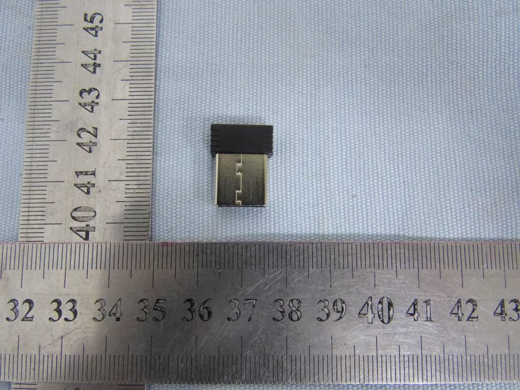
2AJTV-W60X2121
Apr 14, 2020Audio ChatPad
Equipment Class
DXT - Part 15 Low Power Transceiver, Rx Verified