2AJYJHS01Utility Smart Holster Sensor
Utility Associates, INC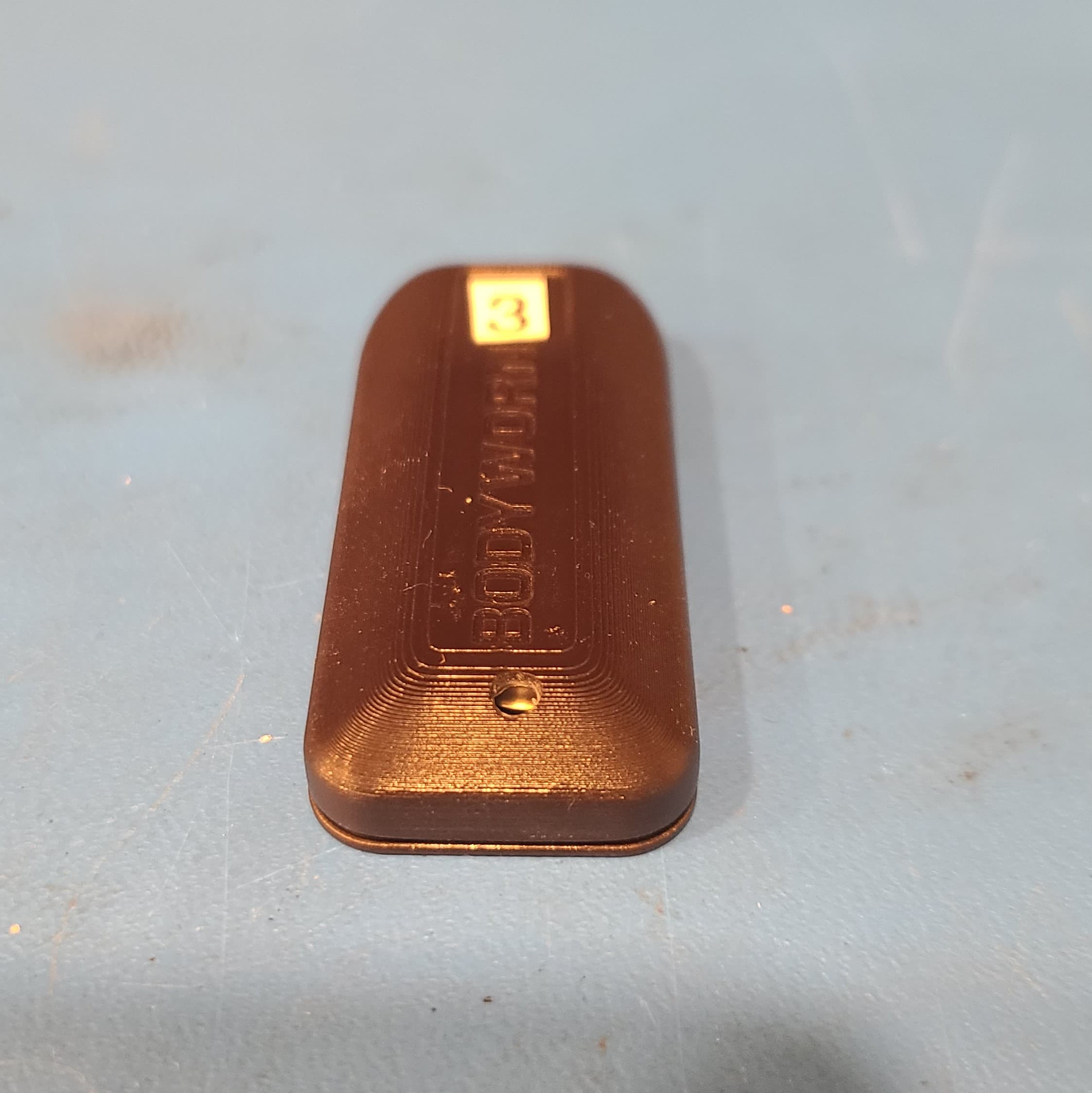
Click to zoom
Application Details
- Equipment Class
- DXX - Part 15 Low Power Communication Device Transmitter
- Date of Grant
- May 18, 2021
- Application Purpose
- Original Equipment
- Date of Application
- May 18, 2021
- Equipment Note
- Utility Smart Holster Sensor
- Frequency Range
- 1.36360000 - 1.36360000
- Company
- Utility Associates, INC
- Country
- United States
Documents & Files
Document Text
Text extracted from the exhibit documents filed with the FCC. Open a document above to read the original.
Users Manual
www.utility.com 250 E. Ponce de Leon Ave., Ste. 700, Decatur, GA 30030 404-816-0300 Smart Holster Sensor - Installation and Users Manual Installing the Sensor NOTE: Please charge sensor for 5 hours before installation 1.Shake primer tube for 10 seconds (once you hear ball rattle.) 2.Break internal tube by squeezing tube at mid-point. 3.Apply cleaner in area where sensor is to be applied. 4.Wait 5 minutes for the primer to dry. 5.Peel back protective liner from the adhesive pad located on bottom of sensor. 6.Place sensor to preferred location. 7.Apply pressure for 30 seconds to allow permanent bond to adhere correctly. Pairing Sensor to BodyWorn Device 1.Place Smart Holster Sensor into pairing mode by connecting up to USB type C charging station. 2.Go to BodyWorn device and scan for device. 3.Pair device on BodyWorn Support Contact Information Email : [email protected] Phone : 1.800.597.4707 Compliance Statement Smart Holster Sensor HS01 FCC ID: 2AJYJHS01 / IC: 27067-HS01 CAN ICES-3 (B)/NMB-3(B) This equipment has been tested and found to comply with the limits for a Class B digital device, pursuant to part 15 of the FCC Rules. These limits are designed to provide reasonable protection against harmful interference in a residential installation. This equipment generates, uses, and can radiate radio frequency energy and, if not installed and used in accordance with the instructions, may cause harmful interference to radio communications. However, there is no guarantee that interference will not occur in a particular installation. If this equipment does cause harmful interference to radio or television reception, which can be determined by turning the equipment off and on, the user is encouraged to try to correct the interference by one or more of the following measures: Reorient or relocate the receiving antenna. Increase the separation between the equipment and receiver. Connect the equipment to an outlet on a circuit different from that to which the receiver is connected. Consult the dealer or an experienced radio/TV technician for help. Changes or modifications not expressly approved by the party responsible for compliance could void the user's authority to operate the equipment This device complies with part 15 of the FCC Rules. Operation is subject to the following two conditions: (1) This device may not cause harmful interference, and (2) this device must accept any interference received, including interference that may cause undesired operation. “This device complies with Industry Canada’s licence-exempt RSSs. Operation is subject to the following two conditions: (1) This device may not cause interference; and (2) This device must accept any interference, including interference that may cause undesired operation of the device.” www.utility.com 250 E. Ponce de Leon Ave, Ste. 700, Decatur GA 30030 404-816-0300 “Le présent appareil est conforme aux CNR d’Industrie Canada applicables aux appareils radio exempts de licence. L’exploitation est autorisée aux deux conditions suivantes : 1) l’appareil ne doit pas produire de brouillage; 2) l’appareil doit accepter tout brouillage radioélectrique subi, même si le brouillage est susceptible d’en compromettre le fonctionnement.”
ID Label/Location Info
IF IN DOUBT, ASK. TITLE: FINAL ASSY HS01 V4DWG_HS01_ASM SCALE: 1:1SHEET 1 OF 1 ZONEDATEAPPROVEDREV. V1. 03/18/21 DESCRIPTION INITIAL RELEASE REVISIONS NOTES: UNLESS OTHERWISE SPECIFIED. 1. FONT AS SHOWN ON PART: CALIBRI 9 PT / 100 HORIZ SPREAD 2. FCC ID / IC ID NUMBER [DOES NOT ITERATE]: FCC ID:2AJYJHS01, IC:27067-HS01 FONT AS SHOWN ON PART: CALIBRI 5 PT / 40 HORIZ SPREAD 3. FCC ID / IC ID NUMBER [DOES NOT ITERATE]: CONTAINS FCC ID:HSW2832, IC:4492A-2832 FONT AS SHOWN ON PART: CALIBRI 5 PT / 40 HORIZ SPREAD 4. MARK AS SHOWN: HS01 PAT. 9,958,228 FONT AS SHOWN ON PART: CALIBRI 10 PT UTILITY ASSOCIATES, INC. 250 E PONCE DE LEON AVE, DECATUR, GA 30030 PHONE: 678-892-8382 EMAIL: [email protected] NAME UTILITYDRAWN -------------- -------------- CHECKED ENG APPR. COMMENTS: UNLESS OTHERWISE SPECIFIED DIMENSIONS ARE IN MM TOLERANCES: ANGULAR: 0 PLACE DECIMAL 1 PLACE DECIMAL 2 PLACEDECIMAL PROPRIETARY AND CONFIDENTIAL THE INFORMATION CONTAINED IN THIS DRAWING IS THE SOLE PROPERTY OF UTILITY ASSIOCIATES, INC. ANY REPRODUCTION IN PART OR AS A WHOLE WITHOUT THE WRITTEN PERMISSION OF UTILITY ASSOCIATES, INC IS PROHIBITED. ALL MATERIALS MUST BE RoHS COMPLIANT, CoC ACCOMPANY FIRST ARTICLE SAMPLE. UNLESS OTHERWISE SPECIFIED. MFG APPR. MATERIAL FINISH SIZE REV DWG. NO. Q.A. 03/18/21 DATE ±0.5° ±0.25 ±0.10 ±0.05 CONTAINS FCC ID: HSW2832, IC: 4492A-2832 FCC ID: 2AJYJHS01, IC: 27067-HS01 HS01 PAT. 9,958,228 VHB TAPE NOT SHOWN USB-C CONNECTOR SCALE 1.500 FCC / IC ID MARK
RF Exposure Info
Report File #: -000 © TÜV SÜD Canada Inc. This test report shall not be reproduced except in full, without written approval of TÜV SÜD Canada Inc. Exhibit: RF Exposure – FCC Client Utility Associates, Inc. Product Smart Holster Sensor (Model: HS01) Standard(s) FCC KDB 447498:2015 Page 2 of 4 Report Issued: 4/27/2021 Report File #: 7169009440R-000 © TÜV SÜD Canada Inc. This test report shall not be reproduced except in full, without written approval of TÜV SÜD Canada Inc. RF Exposure – FCC The device is intended for use on extremities (wrists) and the minimum separation distance from the radiating structure to any part of the body or extremity of a user is 5 mm as stated by the manufacturer during normal operation. The EUT contains a 1.363 MHz transmitter and a modularly certified 2400 – 2483.5 MHz DTS transmitter. General SAR test exclusion guidance: As per FCC KDB 447498 Section 4.3.1 a), the 1-g SAR Test Exclusion Threshold for 100 MHz to 6 GHz at test separation distances ≤ 50 mm is determined by: [(max. power of channel, including tune-up tolerance, mW)/(min. test separation distance, mm)] [√f (GHz) ] ≤ 3.0 Where: f (GHz) is the RF channel transmit frequency in GHz As per FCC KDB 447498 Section 4.3.1b) For 100 MHz to 6 GHz and test separation distances > 50 mm, the 1-g and 10-g SAR test exclusion thresholds are determined by the following {[Power allowed at numeric threshold for 50 mm in step a)] + [(test separation distance – 50 mm)·(f(MHz)/150)]} mW, for 100 MHz to 1500 MH As per FCC KDB 447498 Section 4.3.1 c) the Threshold for frequencies below 100 MHz, at test separation distances ≤ 50 mm is determined by: ½ [1 + log( 100/ f (MHz) ] * Threshold in Section 4.3.1 b) 1) SAR Calculations: 1.363 MHz transmitter The EUT does not have an antenna port. The field was measured at 1 m with a loop antenna; the fundamental frequency falls to the noise floor when measured with a largedistance. The raw measure value is 37.58 dBuV. The final field strength is given by E (dBuV/m) = Received Signal + Antenna Factor + Cable Loss – Pre-Amp Gain + 51.5 = 37.58 dBuV - 6.65 + 0.118 – 33.74 + 51.5 = 48.81 dBuV/m Client Utility Associates, Inc. Product Smart Holster Sensor (Model: HS01) Standard(s) FCC KDB 447498:2015 Page 3 of 4 Report Issued: 4/27/2021 Report File #: 7169009440R-000 © TÜV SÜD Canada Inc. This test report shall not be reproduced except in full, without written approval of TÜV SÜD Canada Inc. The Effective Isotropic Radiate Power in dBm is given by: E.I.R.P (dBm) = E (dBuV/m) -104.77 + 20log(d) where d is in meter. Therefore, for a 1 m measurement distance: E.I.R.P (dBm) = 48.81 - 104.77 +20log(1) = -55.96 dBm (2.53 x 10 -6 mW) Peak E.I.R.P was measured to be 2.53 x 10 -6 mW. As per FCC KDB 447498 Section 4.3.1 a) the power allowed with numerical threshold of 3 and at a separation distance of 50 mm and 100 MHz is: [P (mW) / 50 mm]*[√0.1 GHz] = 3.0 P(@50 mm) = 474.3 mW As per FCC KDB 447498 Section 4.3.1 c)2) the power allowed is ½ [1 + log(100/1.363)] * 474.3 = 679.6 mW The measured peak E.I.R.P of 2.53 x 10 -6 mW is below the power allowed for a 1.363 MHz transmitter. SAR Exclusion Threshold condition is met with peak E.I.R.P. Simultaneous Transmission SAR Calculations As per FCC 2.1093 (d)(2): The SAR limits for general population/uncontrolled exposure are 0.08 W/kg, as averaged over the whole body. Simultaneous transmission is evaluated as per FCC KDB 447498 Section 4.3.2. The equation used is: [(max. power of channel, including tune-up tolerance, mW) / (min. test separation distance, mm)]·[√f(GHz)/x] W/kg, for test separation distances ≤ 50 mm; where x = 7.5 for 1-g SAR. The 1.363 MHz transmitter have a Peak E.I.R.P of 2.53 x 10 -6 mW and the 2.4 GHz transmitter (FCC ID: HSW2832) have a maximum power of 1.216 mW. For 1.363 MHz Transmitter (2.53 x 10 -6 mW / 5 mm)*( √0.001363/7.5) = 2.5 x 10 -9 W/kg Client Utility Associates, Inc. Product Smart Holster Sensor (Model: HS01) Standard(s) FCC KDB 447498:2015 Page 4 of 4 Report Issued: 4/27/2021 Report File #: 7169009440R-000 © TÜV SÜD Canada Inc. This test report shall not be reproduced except in full, without written approval of TÜV SÜD Canada Inc. For 2.4 GHz transmitter (1.216 mW/5)*( √2.4835/7.5) = 0.05 W/kg The sum of the 1-g SAR 0.05 W/kg + 2.5 x 10 -9 W/kg = 0.05 W/kg which is less than 0.08 W/kg.
Test Report
Registration # 6844A-3 Testing Laboratory Certificate #2955.02 R-14023, G-20072 C-14498, T-20060 Registration # CA6844 Page 1 of 45 Report Issued: 5/17/2021 Report File #: 7169009440R-001 © TÜV SÜD Canada Inc. This test report shall not be reproduced except in full, without written approval of TÜV SÜD Canada Inc FCC 15 225 Rev1 RF Test Report As per RSS-210 Issue 10:2019 & FCC Part 15 Subpart 15.209 Low Power Licence Exempt Radio Communication Devices Intentional Radiators on the Smart Holster Sensor Model: HS01 Issued by: TÜV SÜD Canada Inc. 11 Gordon Collins Dr, Gormley, ON, L0H 1G0 Canada Ph: (905) 883-7255 Testing produced for See Appendix A for full client & EUT details. Prepared by: Min Xie, Sr. Project Engineer Reviewed by: Amir Emami, Project Engineer Client Utility Associates, Inc. Product Smart Holster Sensor (Model: HS01) Standard(s) RSS 210 Issue 10:2019 FCC Part 15 Subpart 15.209 Page 2 of 45 Report Issued: 5/17/2021 Report File #: 7169009440R -001 © TÜV SÜD Canada Inc. This test report shall not be reproduced except in full, without written approval of TÜV SÜD Canada Inc Table of Contents Table of Contents ................................................................................................................... 2 Report Scope .......................................................................................................................... 3 Summary ................................................................................................................................ 4 Test Results Summary ....................................................................................................... 5 Notes, Justifications, or Deviations ................................................................................... 6 Sample Calculation(s) ........................................................................................................ 6 Applicable Standards, Specifications and Methods ............................................................... 7 Document Revision Status ..................................................................................................... 8 Definitions and Acronyms ..................................................................................................... 9 Testing Facility .................................................................................................................... 10 Calibrations and Accreditations ....................................................................................... 10 Testing Environmental Conditions and Dates ................................................................. 11 Detailed Test Results Section .............................................................................................. 12 Radiated Emission Field Strength .................................................................................... 13 Transmitter Spurious Radiated Emissions ....................................................................... 18 Power Line Conducted Emissions ................................................................................... 33 20dB and 99% Occupied Bandwidth ............................................................................... 38 Appendix A – EUT Summary .............................................................................................. 42 Appendix B – EUT and Test Setup Photos .......................................................................... 45 Client Utility Associates, Inc. Product Smart Holster Sensor (Model: HS01) Standard(s) RSS 210 Issue 10:2019 FCC Part 15 Subpart 15.209 Page 3 of 45 Report Issued: 5/17/2021 Report File #: 7169009440R -001 © TÜV SÜD Canada Inc. This test report shall not be reproduced except in full, without written approval of TÜV SÜD Canada Inc Report Scope This report addresses the EMC verification testing and test results of the Smart Holster Sensor, Model: HS01,, and is herein referred to as EUT (Equipment Under Test). The EUT was tested for compliance against the following standards: RSS-210 Issue 10:2019, Clause 7.2 FCC Part 15 Subpart C 15.209 Test procedures, results, justifications, and engineering considerations, if any, follow later in this report. This report does not imply product endorsement by any government, accreditation agency, or TÜV SÜD Canada Inc. Opinions or interpretations expressed in this report, if any, are outside the scope of TÜV SÜD Canada Inc accreditations. Any opinions expressed do not necessarily reflect the opinions of TÜV SÜD Canada Inc, unless otherwise stated. Client Utility Associates, Inc. Product Smart Holster Sensor (Model: HS01) Standard(s) RSS 210 Issue 10:2019 FCC Part 15 Subpart 15.209 Page 4 of 45 Report Issued: 5/17/2021 Report File #: 7169009440R -001 © TÜV SÜD Canada Inc. This test report shall not be reproduced except in full, without written approval of TÜV SÜD Canada Inc Summary The results contained in this report relate only to the item(s) tested. EUT FCC Certification #, FCC ID: 2AJYJHS01 EUT Industry Canada Certification #, IC: 27067-HS01 EUT passed all tests performed Yes Tests conducted by Min Xie Report reviewed by Amir Emami For testing dates, see "Testing Environmental Conditions and Dates". Client Utility Associates, Inc. Product Smart Holster Sensor (Model: HS01) Standard(s) RSS 210 Issue 10:2019 FCC Part 15 Subpart 15.209 Page 5 of 45 Report Issued: 5/17/2021 Report File #: 7169009440R -001 © TÜV SÜD Canada Inc. This test report shall not be reproduced except in full, without written approval of TÜV SÜD Canada Inc Test Results Summary Standard/Method Description Class/Limit Result FCC 15.203 Antenna Requirement Unique Pass See Justification FCC 15.209 RSS-GEN – Clause 8.9 Transmitter Spurious Radiated Emissions Quasi-Peak Average Pass FCC 15.207 RSS-GEN – Clause 8.8 Power Line Conducted Emissions Quasi-Peak Average Pass RSS-GEN Section 6.7 Occupied Bandwidth 99% OBW Pass Overall Result Pass If the product as tested…
Text truncated - open the document above for the full version.
Test Setup Photos
Report File #: 7169009440R -000 © TÜV SÜD Canada Inc. This test report shall not be reproduced except in full, without written approval of TÜV SÜD Canada Inc. Exhibit: Test Setup Photos Client Utility Associates, Inc. Product Smart Holster Sensor (Model: HS01) Standard(s) RSS 210 Issue 10:2019 FCC Part 15 Subpart 15.209 Page 2 of 9 Report Issued: 4/26/2021 Report File #:7169009440R-000 © TÜV SÜD Canada Inc. This test report shall not be reproduced except in full, without written approval of TÜV SÜD Canada Inc. Figure 1 ‒ 99% Bandwidth measurement Client Utility Associates, Inc. Product Smart Holster Sensor (Model: HS01) Standard(s) RSS 210 Issue 10:2019 FCC Part 15 Subpart 15.209 Page 3 of 9 Report Issued: 4/26/2021 Report File #:7169009440R-000 © TÜV SÜD Canada Inc. This test report shall not be reproduced except in full, without written approval of TÜV SÜD Canada Inc. Figure 2 ‒ Radiated Emissions Setup 9kHz to 30MHz Client Utility Associates, Inc. Product Smart Holster Sensor (Model: HS01) Standard(s) RSS 210 Issue 10:2019 FCC Part 15 Subpart 15.209 Page 4 of 9 Report Issued: 4/26/2021 Report File #:7169009440R-000 © TÜV SÜD Canada Inc. This test report shall not be reproduced except in full, without written approval of TÜV SÜD Canada Inc. Figure 3 ‒ Radiated Emissions Setup 30MHz to 1GHz Note: As per ANSI C63.10-2013 Clause 6.3.1, below 1GHz, the height of the EUT was set to 80cm. Above 1GHz, the height was raised to 1.5m. Client Utility Associates, Inc. Product Smart Holster Sensor (Model: HS01) Standard(s) RSS 210 Issue 10:2019 FCC Part 15 Subpart 15.209 Page 5 of 9 Report Issued: 4/26/2021 Report File #:7169009440R-000 © TÜV SÜD Canada Inc. This test report shall not be reproduced except in full, without written approval of TÜV SÜD Canada Inc. Figure 4 ‒ Radiated Emissions Setup 1GHz to 6GHz Spurious Scans Note: As per ANSI C63.10-2013 Clause 6.3.1, above 1GHz, the height of the EUT was set to 1.5m. Client Utility Associates, Inc. Product Smart Holster Sensor (Model: HS01) Standard(s) RSS 210 Issue 10:2019 FCC Part 15 Subpart 15.209 Page 6 of 9 Report Issued: 4/26/2021 Report File #:7169009440R-000 © TÜV SÜD Canada Inc. This test report shall not be reproduced except in full, without written approval of TÜV SÜD Canada Inc. Figure 5 ‒ Radiated Emissions Setup 6GHz to 12GHz Spurious Scans & Band-Edge Measurements Client Utility Associates, Inc. Product Smart Holster Sensor (Model: HS01) Standard(s) RSS 210 Issue 10:2019 FCC Part 15 Subpart 15.209 Page 7 of 9 Report Issued: 4/26/2021 Report File #:7169009440R-000 © TÜV SÜD Canada Inc. This test report shall not be reproduced except in full, without written approval of TÜV SÜD Canada Inc. Figure 6 ‒ Radiated Emissions Setup 18GHz to 26GHz Spurious Scans Client Utility Associates, Inc. Product Smart Holster Sensor (Model: HS01) Standard(s) RSS 210 Issue 10:2019 FCC Part 15 Subpart 15.209 Page 8 of 9 Report Issued: 4/26/2021 Report File #:7169009440R-000 © TÜV SÜD Canada Inc. This test report shall not be reproduced except in full, without written approval of TÜV SÜD Canada Inc. Figure 7 ‒ Power Line Conducted Emissions Setup Client Utility Associates, Inc. Product Smart Holster Sensor (Model: HS01) Standard(s) RSS 210 Issue 10:2019 FCC Part 15 Subpart 15.209 Page 9 of 9 Report Issued: 4/26/2021 Report File #:7169009440R-000 © TÜV SÜD Canada Inc. This test report shall not be reproduced except in full, without written approval of TÜV SÜD Canada Inc. Figure 8 ‒ Power Line Conducted Emissions Setup
Contact Information
Applicant
Jonathan Kirk McChristian
Test Firm
TUV SUD CANADA (Gormley)William (Mac) Elliott
[email protected]813-284-2736
Technical Specifications
| # | Rule Parts | Frequency Range | Power Output |
|---|---|---|---|
| 1 | 15C | 1.3636 MHz - 1.3636 MHz | - |