2AJYL-AB23AIRBOLT CELLULAR GPS
AirBolt Pty Ltd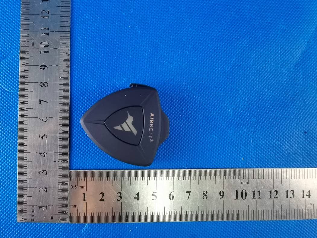
Click to zoom
Application Details
- Equipment Class
- DTS - Digital Transmission System
- Date of Grant
- Apr 09, 2023
- Application Purpose
- Original Equipment
- Date of Application
- Apr 09, 2023
- Equipment Note
- AIRBOLT CELLULAR GPS
- Frequency Range
- 2402.00000000 - 2480.00000000
- Company
- AirBolt Pty Ltd
- Country
- Australia
Documents & Files
Document Text
Text extracted from the exhibit documents filed with the FCC. Open a document above to read the original.
Users Manual
The Cellular GPS Instruction Manual Retrieve goods with caution. Your AirBolt is designed to help you find your goods. However, in case of theft of your valuables, we strongly advise against self retrieval and always encourage working with law enforcement in your local area to co-ordinate doing so. Please only retreive goods when you know for certain that it is not an unsafe or potentially unsafe situation. No liability for loss or damage. AirBolt assumes no liability whatsoever for items or valuables that may ultimately end up being lost or have an AirBolt Device placed on them. Whilst we’ve engineered the product to the highest standards and are continually developing and updating the software, a tracked item may ultimately become lost and irretrievable for a variety of reasons outside of our and the users control, from theft, to deliberate damage or removal. The AirBolt GPS is not a replacement for due care of your goods, valuables or loved ones etc. Using in good faith. The AirBolt GPS is a powerful tracker designed for good and to be always used in good faith. There’s a range of ways to use trackers for good and there are some for not so good and may invade other peoples privacy. Although it’s incredibly unlikely it’ll be used in that way we’re just mindful to reiterate our good faith policy. Terms and conditions. The disclaimers above do not constitute our complete set of terms and conditions. For a full set of terms and conditions see https://theairbolt.com/pages/terms-and-conditions. By downloading the AirBolt app and signing up, you are agreeing to the terms and conditions set forth above. DISCLAIMERS Welcome and congrats on purchasing an AirBolt GPS! Our quick-start guide has been written to give you a few hints, tips and tricks to get the most out of your device across a range of common scenarios. In addition to this guide, if you'd like a video walkthrough of how to get started, simply scan the QR code above. Get the AirBolt app Step 1. Get the latest version of the AirBolt app and make losing things a thing of the past. You can also control all your AirBolt devices via our customisable Web Platform and view notifications on your Apple watch! You can visit the Web Platform at manage.theairbolt.com Pairing the GPS Step 2. Once you’ve signed up for an account or logged in using your existing one press the “+” button on the app and follow the steps within the app. Written instructions appear on the next page too as back up. If you’re already paired you can skip the next page ;) Pairing (continued) Step 2. 1. Once you’ve signed up to the app, or signed into your account please press the + button to begin pairing. 2. Please wake up your device by inserting the included USB-C cable into your device and the other end into a power source. The AirBolt GPS should light up. 3.Press the button on the AirBolt GPS and then press “Next”. 4. The app will search for your GPS and pair with it. 5.Once paired, please choose a name for your AirBolt and feel free to select a picture. Press “Next” when ready. This is the text based setup instructions that the app guides your through. If you’re already paired you can skip this page! Choose your Operating Mode Step 3. It's now time to optimize your AirBolt. Select the option that suits your need the most. Optimize for responsiveness, or, Optimize for battery life. Key tip! Combine this with accelerometer settings so if your item does move you can be alerted. See chapter I. Battery management for further details. Setting up your Data Package Step 4. Your AirBolt GPS requires a cellular subscription to be able to communicate with you. Please activate it by clicking the subscribe button within the app. Doing so, will launch our web platform in a new window. Here you can select your plan for your device and activate. Once complete, you can use the app or web platform to start using your device. Congrats, you’re all set up and ready to go! The rest of this guide gives you best practices, tips and tricks of how to setup the device for tracking certain things like pets, bikes or vehicles and an introduction to key features like Geofencing and Alerts. I. Battery management III. GeofencingII. Signal strength tips IV. MovementVI. Water sensingV. Temperature VII. SOS alertsVIII. Charging Select mode. Select whether you want to optimize for battery life or reporting interval. Interval timings. The more "pings", or the more accurate you want your location (i.e. using GPS over cellular) the more battery is used. Accelerometer / movement detection. If you just want to know if your device moves from where you left it. Reduce the intervals as much as practically possible and turn on the accelerometer to notify you if it moves. Some of these variables are operating mode, interval timings, signal strength and accelerometer. Maximizing the battery life of your GPS relies on a number of key variables. I. Battery management II. Signal strength tips Your AirBolt GPS has been designed to detect both cellular and GPS signals allowing for a variety of use cases. Cellular signal doesn't rely on any particular location or direction of the device, however to maximise GPS signal it is best to face the device upwards. For example, with our pet collar attachment, place the AirBolt GPS directed towards the sky, rather than in front of your pet. Similarly when putting the AirBolt GPS on bikes, trailers, etc it is best to affix the device in a way where the device faces up. Getting the best from your GPS Signal. Face upwards for best signal * Geo-fencing works when your GPS reports its location and depends on your set intervals. We strongly recommend enabling the accelerometer with geo-fencing so you don't miss a beat. III. Geofencing One of our most popular features is geo-fencing and creating alerts if your GPS strays further than intended. Set the boundaries of where you want your tracker to roam, and get notified if your tracker goes outside your defined range. Movement detection …
Text truncated - open the document above for the full version.
Attestation Statements
AirBolt Pty Ltd The information provided in this letter is based on the referenced rule parts of Title 47 of the CFR as well as KDB 986446 D01. An expiration date for this letter does not exist. In case the U.S. agent changes, the grantee is obligated to notify the FCC. Federal Communications Commission Authorization and Evaluation Division Equipment Authorization Branch 7435 Oakland Mills Road Columbia, MD 21046 4/4/2023 U.S. Agent Designation AirBolt Pty Ltd acknowledges their consent for the following contact located in the United States to act as their agent for service of process for the equipment for which authorization is sought (FCC ID: 2AJYL-AB23): Name and company of U.S. agent: Tim Payne, FCC US Agent, LLC Physical U.S. address of agent: 3722 Illinois Avenue, Saint Charles, IL, 60174, USA FRN of U.S. agent: 0033402884 Email address of U.S. agent: [email protected] FCC US Agent, LLC acknowledges their obligation to accept service of process on behalf of AirBolt Pty Ltd. AirBolt Pty Ltd accepts its obligation to maintain an agent for service of process in the United States for no less than one year after either the grantee has permanently terminated all marketing and importation of the applicable equipment within the U.S., or the conclusion of any Commission-related administrative or judicial proceeding involving the equipment, whichever is later. By signing this form, we confirm the above and that we are aware of the application requirements listed under § 2.911(d)(7). Sincerely, Signature Kabir Sidhu CEO AirBolt Pty Ltd Signature Tim Payne Manager FCC US Agent, LLC 48_[model] US_Agent_2.911(d)(7)-U, V03
External Photos
Page 1 of 3 FCC ID: 2AJYL-AB23 Dongguan Yaxu (AiT) Technology Limited No.22, Jinqianling 3rd Street, Jitigang, Huangjiang, Dongguan, Guangdong, China. External Photos Photo 1 Photo 2 Page 2 of 3 FCC ID: 2AJYL-AB23 Dongguan Yaxu (AiT) Technology Limited No.22, Jinqianling 3rd Street, Jitigang, Huangjiang, Dongguan, Guangdong, China. Photo 3 Photo 4 Page 3 of 3 FCC ID: 2AJYL-AB23 Dongguan Yaxu (AiT) Technology Limited No.22, Jinqianling 3rd Street, Jitigang, Huangjiang, Dongguan, Guangdong, China. Photo 5 Photo 6 ------End------
ID Label/Location Info
FCC ID Label FCC ID : 2AJYL-AB23
Internal Photos
Page 1 of 3 FCC ID: 2AJYL-AB23 Dongguan Yaxu (AiT) Technology Limited No.22, Jinqianling 3rd Street, Jitigang, Huangjiang, Dongguan, Guangdong, China. Internal Photos Photo 1 Photo 2 LTE Antenna GPS Antenna Page 2 of 3 FCC ID: 2AJYL-AB23 Dongguan Yaxu (AiT) Technology Limited No.22, Jinqianling 3rd Street, Jitigang, Huangjiang, Dongguan, Guangdong, China. Photo 3 Photo 4 Page 3 of 3 FCC ID: 2AJYL-AB23 Dongguan Yaxu (AiT) Technology Limited No.22, Jinqianling 3rd Street, Jitigang, Huangjiang, Dongguan, Guangdong, China. Photo 5 Photo 6 ------End------ BT Antenna
RF Exposure Info
Page1of5ReportNo.:AIT22122704FH Page1of5 MPETESTREPORT FCCID:2AJYL-AB23 ProductName:AIRBOLTCELLULARGPS BrandName:AIRBOLT TestModel:ABGPS-23 SeriesModel:N/A Applicant:AirBoltPtyLtd Address:POBox192,Bulleen,Victoria,Australia3105 Manufacturer:BOTERLANTECHNOLOGYCO.,LIMITED Address:4F,BulidingB2,Guangshenhighandnewscienceandtechnologypark Youmagang,Jiangshi,Gongming,Guangmingnewzone,Shenzhen, Guangdong,China DateofReceipt: 2022.12.27 DateofTest: 2022.12.27-2023.01.06 IssuedDate: 2023.01.06 ReportVersion:V1.0 TestSample:EngineeringSampleNo.:AIT22122704-1 Standard(s):FCCTitle47Part2.1091 KDB447498001GeneralRFexposureguidancev06 Lab:DongguanYaxu(AiT)TechnologyLimited Add:No.22,Jinqianling3rdStreet,Jitigang,Huangjiang,Dongguan, Guangdong,China Tel.:+86-769-82020499Fax.:+86-769-82020495 ThisdevicedescribedabovehasbeentestedbyDongguanYaxu(AiT)TechnologyLimitedandthe testresultsshowthattheequipmentundertest(EUT)isincompliancewiththeFCCrequirements. Anditisapplicableonlytothetestedsampleidentifiedinthereport. Note:Thisreportshallnotbereproducedexceptinfull,withoutthewrittenapprovalofDongguanYaxu(AiT) TechnologyLimited,thisdocumentmaybealteredorrevisedbyDongguanYaxu(AiT)TechnologyLimited, personalonly,andshallbenotedintherevisionofthedocument.Thistestreportmustnotbeusedbytheclient toclaimproductendorsement. Reviewedby:Approvedby: SimbahuangSealChen Page2of5ReportNo.:AIT22122704FH Page2of5 RevisionHistory RevisionIssueDateRevisionsRevisedBy V1.02023.01.06InitialIssueSealChen Page3of5ReportNo.:AIT22122704FH Page3of5 1.TESTFACILITY Company:DongguanYaxu(AiT)TechnologyLimited Address: No.22,Jinqianling3rdStreet,Jitigang,Huangjiang,Dongguan, Guangdong,China CNASRegistrationNumber:CNASL6177 A2LARegistrationNumber:6317.01 FCCAccreditedLab.Designation Number: CN1313 FCCTestFirmRegistrationNumber:703111 2.MPECALCULATIONMETHOD CalculationMethodofRFSafetyDistance: where: S=powerdensity P=powerinputtotheantenna G=powergainoftheantennainthedirectionofinterestrelativetoanisotropicradiator R=distancetothecenterofradiationoftheantenna Page4of5ReportNo.:AIT22122704FH Page4of5 AntennaSpecification: ForBLE: Ant.BrandModelNameAntennaTypeConnectorGain(dBi) 1N/AN/AN/AN/A1.50 ForLTE-BAND2: Ant.BrandModelNameAntennaTypeConnectorGain(dBi) 1N/AN/AN/AN/A1.39 ForLTE-BAND4: Ant.BrandModelNameAntennaTypeConnectorGain(dBi) 1N/AN/AN/AN/A0.76 ForLTE-BAND12: Ant.BrandModelNameAntennaTypeConnectorGain(dBi) 1N/AN/AN/AN/A-0.49 ForLTE-band13: Ant.BrandModelNameAntennaTypeConnectorGain(dBi) 1N/AN/AN/AN/A2.42 Note:Theantennagainisprovidedbythemanufacturer. Page5of5ReportNo.:AIT22122704FH Page5of5 3.TESTRESULTS ForBLE: Directional Gain (dBi) Directional Gain (numeric) Max.Output Power (dBm) Max.Output Power (mW) PowerDensity (S)(mW/cm 2 ) LimitofPower Density(S) (mW/cm 2 ) TestResult 1.501.412.111.62550.00461Complies ForLTE-BAND2: Directional Gain (dBi) Directional Gain (numeric) Max.Output Power (dBm) Max.Output Power (mW) PowerDensity (S)(mW/cm 2 ) LimitofPower Density(S) (mW/cm 2 ) TestResult 1.391.3824.00251.1890.06881Complies ForLTE-BAND4: Directional Gain (dBi) Directional Gain (numeric) Max.Output Power (dBm) Max.Output Power (mW) PowerDensity (S)(mW/cm 2 ) LimitofPower Density(S) (mW/cm 2 ) TestResult 0.761.1923.89244.9060.05801Complies ForLTE-BAND12: Directional Gain (dBi) Directional Gain (numeric) Max.Output Power (dBm) Max.Output Power (mW) PowerDensity (S)(mW/cm 2 ) LimitofPower Density(S) (mW/cm 2 ) TestResult -0.490.8921.74149.2790.02650.47Complies ForLTE-BAND13: Directional Gain (dBi) Directional Gain (numeric) Max.Output Power (dBm) Max.Output Power (mW) PowerDensity (S)(mW/cm 2 ) LimitofPower Density(S) (mW/cm 2 ) TestResult 2.421.7524.72296.4830.10300.52Complies Note: 1.Onlytheworstcaserecorded. 2.TheBT,LTEbandcantransmitsimultaneously. 3.Outputpowerincludingtuneuptolerance. 4.Thecalculateddistanceis20cm. TransmitSimultaneously(Worst): PowerDensity: LTE-Band13/0.52+BLE/1=0.10983/0.52+0.00056/1=0.211<1 4.CONCLUSION Remark:EUTmeetsthebasicrequirementsinthestandard. ----ENDOFREPORT----
Test Report
Page 1 of 68 ReportNo .: AIT22122704FW1 DongguanYaxu(AiT)TechnologyLimited No.22,Jinqianling3rd Street,Jitigang, Huangjiang,Dongguan,Guangdong,China. RF TEST REPORT FCC ID: 2AJYL-AB23 ProductName:AIRBOLTCELLULARGPS BrandName:AIRBOLT Test Model:ABGPS-23 SeriesModel:N/A Applicant:AirBoltPty Ltd Address:PO Box 192,Bulleen,Victoria,Australia3105 Manufacturer:BOTERLANTECHNOLOGYCO.,LIMITED Address:4F,BulidingB2,Guangshenhigh and new scienceand technologypark Youmagang,Jiangshi,Gongming,Guangmingnew zone,Shenzhen, Guangdong,China Date of Receipt:2022.12.27 Date of Test:2022.12.27- 202 3.01.06 IssuedDate:202 3.01.06 ReportVersion:V1.0 Test Sample:EngineeringSampleNo.: AIT22122704-1 Standard(s): FCCCFR Title 47 Part 15 SubpartC Section15.247 Lab:DongguanYaxu(AiT)TechnologyLimited Add:No.22,Jinqianling3rd Street,Jitigang,Huangjiang,Dongguan, Guangdong,China Tel.: +86-769-82020499Fax.:+86-769-82020495 This devicedescribedabovehas beentestedby DongguanYaxu(AiT)TechnologyLimitedand the test resultsshowthat the equipmentundertest (EUT)is in compliancewith the FCCrequirements. And it is applicableonly to the testedsampleidentifiedin the report. Note:This reportshallnot be reproducedexceptin full, withoutthe writtenapprovalof DongguanYaxu(AiT) TechnologyLimited,this documentmay be alteredor revisedby DongguanYaxu(AiT)TechnologyLimited, personalonly, and shallbe notedin the revisionof the document.This test reportmustnot be usedby the clientto claimproductendorsement. Reviewedby:Approvedby: SimbahuangSeal Chen Page 2 of 68 ReportNo .: AIT22122704FW1 DongguanYaxu(AiT)TechnologyLimited No.22,Jinqianling3rd Street,Jitigang, Huangjiang,Dongguan,Guangdong,China. Table of Contents 1 .TESTSUMMARY...................................................................................................................................................................5 1.1 Statementof the MeasurementUncertainty...........................................................................................5 1.2 MeasurementUncertainty.......................................................................................................................5 2 .TESTFACILITY......................................................................................................................................................................6 2.1 Deviationfrom standard..........................................................................................................................6 2.2 Abnormalitiesfrom standardconditions..................................................................................................6 3 .GENERALINFORMATION..................................................................................................................................................7 3.1 Test frequencies......................................................................................................................................8 3.2 EUT PeripheralList .................................................................................................................................8 3.3 Test PeripheralList ..................................................................................................................................8 3.4 TESTMETHODOLOGY..........................................................................................................................9 3.5 Descriptionof Test Modes.....................................................................................................................10 4 .EQUIPMENTUSEDDURINGTEST.................................................................................................................................11 5 .EN300328 TEST REQUIREMENTS..................................................................................................................................12 5.1 Antennarequirement.............................................................................................................................12 6.1.1Standardreq Suirement:..............................................................................................................12 6.1.2EUT Antenna:..............................................................................................................................12 5.2 On Timeand DutyCycle.......................................................................................................................13 6.2.1Standardrequirement:................................................................................................................13 6.2.2MeasuringInstrumentsand Setting:...........................................................................................13 6.2.3Test Procedures..........................................................................................................................13 6.2.4Test SetupLayout.......................................................................................................................13 6.2.5EUT OperationduringTest .........................................................................................................13 6.2.6Test result....................................................................................................................................13 5.3 MaximumConductedOutputPeakPowerMeasurement....................................................................14 6.3.1Standardrequirement:................................................................................................................14 6.3.2MeasuringInstruments:..............................................................................................................14 6.3.3Test Procedures:.........................................................................................................................14 6.3.4Test SetupLayout.......................................................................................................................14 6.3.5EUT Operationdu…
Text truncated - open the document above for the full version.
Test Report
AEC-Q200 Qualification Available New Global P/N 2450AT18D0100001 Legacy P/N 2450AT18D0100 Detail Specification: Page 1 of 7 Top Bottom ¹Efficiency measured on Johanson's evaluation board PN 2450AT18D0100001CE1 No. ±± 1 ±± 2 ±± 3 4 ±± Function 1: Antenna fed from left Function 2: Antenna fed from right https://www.johansontechnology.com 4001 Calle Tecate • Camarillo, CA 93012 • TEL 805.389.1166 FAX 805.389.1821 Ver. 4.4 2021 Johanson Technology, Inc. All Rights Reserved Frequency (GHz) Peak Gain (dBi) Average Gain (dBi) Radiated Efficiency¹ 2.4 - 2.5 1.5 typ. (XZ-total) -1.0 typ. (XZ-total) 72% Humidity 45 - 75% RH 50 3 max. (CW) -40 to +125°C Recommended Storage Conditions and Period for unused Product on T&R 18 months max. +5 to +35°C Return Loss (dB) Impedance (Ω) Input Power (W) Operating Temperature 10 min. e.g. 2450AT18D0100001B e.g. 2450AT18D0100001E Packing Style T & R 3,000 Reel Quantity (pcs./reel) Bulk (loose pcs.) Part Number Explanation (See last page for more info on new and legacy part numbers) e.g. 2450AT18D0100001(B or S) Suffix = B Suffix = E 100% TinSuffix = None Terminal Configuration FEED GND GND GND GND GND GND FEED Function 1Function 2 b 0.0200.500.20.008 a 0.0120.30+0.1 / -0.2 +0.004 / -0.008 1.200.10.004 2450AT18D0100001CE1 mm Evaluation Board Johanson Technology, Inc. reserves the right to make design changes without notice. All sales are subject to Johanson Technology, Inc. terms and conditions. P/N Suffix Mechanical Dimensions In L 0.1260.0083.200.2 W 0.0630.0081.600.2 T 0.047 High Frequency Ceramic Solutions 8/24/2022 Let us help you with the antenna design, optimization, and tuning! 2450AT18D0100001 2.45 GHz SMD Antenna, EIA 1206, Detuning resilient, Edge Mount Design https://www.johansontechnology.com/ask-a-question General Specifications New Global Part Number 1 2 4 3 b T L a w b New Global P/N 2450AT18D0100001 Legacy P/N 2450AT18D0100 Detail Specification:Page 2 of 7 https://www.johansontechnology.com 4001 Calle Tecate • Camarillo, CA 93012 • TEL 805.389.1166 FAX 805.389.1821 Ver. 4.4 2021 Johanson Technology, Inc. All Rights Reserved High Frequency Ceramic Solutions 8/24/2022 Mounting Considerations 1: Evaluation Board (Standard Layout) Johanson Technology, Inc. reserves the right to make design changes without notice. All sales are subject to Johanson Technology, Inc. terms and conditions. 2.45 GHz SMD Antenna, EIA 1206, Detuning resilient, Edge Mount Design To order a pre-tuned 50Ω EVB with a female SMA connector click here: https:// www.johansontechnology.com/request-a-sample Reference p/n: 2450AT18D0100001CE1 Units inmm Ground Vias Feeding Line Ground clearance 40mm 20mm Matching Circuits Measured radiated efficiency of 2450AT18D0100 on this evaluation board is 72% 1.02.01.0 0.6 0.7 0.6 4.1 4.0 0 Ohm Matching Circuits No ground, metal PCB layers, or other metallic components like batteries directly underneath antenna! Ground Ground Ground 6.0 Land Solder Resist 50Ω Trace (Grounded CPWG type is preferred) GND Vias New Global P/N 2450AT18D0100001 Legacy P/N 2450AT18D0100 Detail Specification:Page 3 of 7 https://www.johansontechnology.com 4001 Calle Tecate • Camarillo, CA 93012 • TEL 805.389.1166 FAX 805.389.1821 Ver. 4.4 2021 Johanson Technology, Inc. All Rights Reserved High Frequency Ceramic Solutions 8/24/2022 Mounting Considerations 1: Electrical Performance @25°C Johanson Technology, Inc. reserves the right to make design changes without notice. All sales are subject to Johanson Technology, Inc. terms and conditions. 2.45 GHz SMD Antenna, EIA 1206, Detuning resilient, Edge Mount Design MeasuredReturn Loss Would you like the antenna layout? Have antenna tuning issues? Please contact us if you have any questions regarding the implementation of this antenna in your PCB's layout. We'll be happy to guide you to maximize the antenna's performance. Contact our applications engineers at: https://www.johansontechnology.com/ask-a-question 2.22.42.62.82.03.0 -20 -10 -30 0 f req, GHz dB(S(1,1)) m1 m2 m3 m1 f req= dB(S(1,1))=-13.935 2.400GHz m2 f req= dB(S(1,1))=-14.774 2.500GHz m3 f req= dB(S(1,1))=-24.894 2.450GHz New Global P/N 2450AT18D0100001 Legacy P/N 2450AT18D0100 Detail Specification:Page 4 of 7 https://www.johansontechnology.com 4001 Calle Tecate • Camarillo, CA 93012 • TEL 805.389.1166 FAX 805.389.1821 Ver. 4.4 2021 Johanson Technology, Inc. All Rights Reserved High Frequency Ceramic Solutions 8/24/2022 Mounting Considerations 1: Typical 2D radiation patterns @ 2.44GHz Johanson Technology, Inc. reserves the right to make design changes without notice. All sales are subject to Johanson Technology, Inc. terms and conditions. 2.45 GHz SMD Antenna, EIA 1206, Detuning resilient, Edge Mount Design YZ-plane XZ-plane XY-plane θ +Z (θ= 0°) +Y (θ= 90°) -Y -Z θ +Z (θ= 0°) +X (θ= 90°) -X -Z φ +X (φ= 0°) -X +Y (φ= 90°) -Y +Z -Z +Y -Y +Z -Z +X -X +X -X +Y -Y New Global P/N 2450AT18D0100001 Legacy P/N 2450AT18D0100 Detail Specification:Page 5 of 7 https://www.johansontechnology.com 4001 Calle Tecate • Camarillo, CA 93012 • TEL 805.389.1166 FAX 805.389.1821 Ver. 4.4 2021 Johanson Technology, Inc. All Rights Reserved Johanson Technology, Inc. reserves the right to make design changes without notice. All sales are subject to Johanson Technology, Inc. terms and conditions. Mounting Considerations 2: Small Clearance or "Thin edge" Applications* 2.450.3 (XZ-plane) High Frequency Ceramic Solutions 2.45 GHz SMD Antenna, EIA 1206, Detuning resilient, Edge Mount Design 8/24/2022 Mounting Considerations 3: "Thind edge" application on circular PCB Frequency (GHz)Peak Gain (dBi)Average Gain (dBi)Radiated Efficiency (%) -3.6 (XZ-plane)66 Units inmm Land Solder Resist *Evaluationboard not available * 1.02.01.0 0.6 0.7 0.6 1.5 8.0 Matching Circuits Ground 0.6 2.8 0.6 3.4 3.4 GND clearance *Evaluationboard not available 50Ω Trace (Grounded CPWG type is preferred) No ground, metal PCB layers, or other metallic components like batteries and displays directly underneath antenna! Groun…
Text truncated - open the document above for the full version.
Test Setup Photos
Page 1 of 2 FCC ID: 2AJYL-AB23 Dongguan Yaxu (AiT) Technology Limited No.22, Jinqianling 3rd Street, Jitigang, Huangjiang, Dongguan, Guangdong, China. Test Setup Photo Radiated Emission Page 2 of 2 FCC ID: 2AJYL-AB23 Dongguan Yaxu (AiT) Technology Limited No.22, Jinqianling 3rd Street, Jitigang, Huangjiang, Dongguan, Guangdong, China. Conducted Emission ------End------
Contact Information
Applicant
Kabir Sidhu(CEO)
Test Firm
Dongguan Yaxu (AiT) Technology LimitedCoin Tang
[email protected]+86 0769-82020499-21
Technical Specifications
| # | Rule Parts | Frequency Range | Power Output |
|---|---|---|---|
| 1 | 15C | 2.40 GHz - 2.48 GHz | 1.60 mW |