2AJZYCL2325Watch Charger with Multi Cables
Ningbo Gecen Promotion & Gift Co., Ltd
Click to zoom
Application Details
- Equipment Class
- DCD - Part 15 Low Power Transmitter Below 1705 kHz
- Date of Grant
- Jul 07, 2024
- Application Purpose
- Original Equipment
- Date of Application
- Jul 07, 2024
- Equipment Note
- Watch Charger with Multi Cables
- Frequency Range
- 0.31900000 - 0.31900000
- Country
- China
Documents & Files
Document Text
Text extracted from the exhibit documents filed with the FCC. Open a document above to read the original.
Users Manual
FCC STATEMENT Te c h S p ecifications Input:5V/2A Output:5V/2A Power Delivery:1-2.5W Instructions Safety Precautions MADE IN CHINA FCC ID:2AJZYCL2325 1 1.Wireless Charging Pad NOTE: This equipment has been tested and found to comply with the limits for a Class B digital device, pursuant to part 15 of the FCC Rules.These limits are designed to provide reasonable protection against harmful interference in a residential installation. This equipment generates uses and can rradiate radio frequency energy and, if not installed and used in accordance with the instructions, may cause harmful interference to radio communications. However, there is no guarantee that interference will not occur in a particular installation. If this equipment does cause harmful interference to radio or television reception, which can be determined by turning the equequipment off and on, the user is encouraged to try to correct the interference by one or more of the following measures: - Reorient or relocate the receiving antenna. - Increase the separation between the equipment and receiver. -Connect the equipment into an outlet on a ccircuit different from that to which the receiver is connected. -Consult the dealer or an experienced radio/TV technician for help Changes or modifications not expressly approved by the party responsible for compliance could void the user's authority to operate the equipment. TThis device complies with Part 15 of the FCC Rules. Operation is subject to the following two conditions: (1) this device may not cause harmful interference, and (2) this device must accept any interference received,including interference that may cause undesired operation. 1. Read all the instructions before using the product. 2. To reduce the risk of injury,close supervision is necessary when the product is used near children. 3. Do not expose the devide to moisture. 4. Do not use the device in excess of its output rating.Overload outputs above rating may result in a risk of fire or injury. 5. Do not use the devide if damaged or modified. 6. Damaged or modified batteries may exhibit unpredictable behavior resulting in fire explosion or risk of injury. 7. Do not disassemble the device.Take it to a qualified service person when service or repair is required.Incorrect reassembly may result a risk of fire or injury 8. Do not expose the device to fire or excessive temperature.Exposure to fire or temperatures above 212F° may casue explosion. 9. Have servicing performed by a qualified repair person using only identical replacement parts. 1010. This will ensure that the safety of the product is maintained. 11. Do not overcharge watch.Unit may get hot with excessive use.Remove watch when it is fully charged.Never charge for more than 7 hours at a time. WARNING-When using this product,basic precautions should always be followed: RF Exposure Warning Statements: This equipment complies with FCC radiation exposure limits set forth for an uncontrolled environment. This equipment shall be installed and operated with minimum distance 20cm between the rradiator & body. Charging watch devices: 1. Check your watch supporting with wireless charging,it will be listed in the manufacturer’s specifications. 2. Simply place the enabled device atop the wireless charging pad.Your device should show the charging indication. 3. When completely charged,remove the device from the charging pad. Watch Ch a r g e r With Multi Cables Instruction Manual 25238
Cover Letter(s)
NINGBO GECEN PROMOTION & GIFT CO.,LTD. B106-109,NO.535 QINGSHUIQIAO ROAD,HI-TECH ZONE,NINGBO,CHINA Declaration Letter FCC ID: 2AJZYCL2325 Pursuant to KDB 680106 of the NINGBO GECEN PROMOTION & GIFT CO.,LTD. Hereby declare our product which is an inductive wireless power transfer applications that meet all of the following requirements are not required to submit a KDB inquiry for devices approved usinga PAG for equipment approved using certification to address RF exposure compliance. The EUT does comply with item 5.2 of KDB 680106 D01 Wireless Power Transfer v04 as follows table: Requirements of KDB 680106 Description (1) The power transfer frequency is below 1MHz. The device operate in the frequency range 319kHz. (2) The output power from each transmitting element (e.g., coil) is less than or equal to 15 watts. The maximum output power of the primary coil is 2.5W. (3) A client device providing the maximum permitted load is placed in physical contact with the transmitter (i.e., the surfaces of the transmitter and client device enclosures need to be in physical contact) Client device is placed directly in contact with the transmitter. (4) Only $2.1091-Mobile exposure conditions apply (i.e., this provision does not cover $ 2.1093-Portable exposure conditions). Device can be used in Mobile conditions. (5) The E-field and H-field strengths, at and beyond 20 cm surrounding the device surface, are demonstrated to be less than 50% of the applicable MPE limit, per KDB 447498, Table 1. These measurements shall be taken along the principal axes of the device, with one axis oriented along the direction of the estimated maximum field strength, and for three points per axis or until a l/d (inverse distance from the emitter structure) field strength decay is observed. Symmetry considerations may be used for test reduction purposes. The device shall be operated in documented worst-case compliance scenarios (i.e., the ones that lead to the maximum field components), and while all the radiating structures (e.g., coils or antennas) that by design can simultaneously transmit are energized at their nominal maximum power. The EUT H-field strengths at 20cm surrounding the device and 20 cm above the top surface from all simultaneous transmitting coils are demonstrated to be less than 50% of the MPE limit. (6) For systems with more than one radiating structure, the conditions specified in (5) must be met when the system is fully loaded (i.e., clients absorbing maximum power available), and with all the radiating structures operating at maximum power at the same time, as per design conditions. If the design allows one or more radiating structures to be powered at a higher level while other radiating structures are not powered, then those cases must be tested as well. For instance, a device may use three RF coils powered at 5 W, or one coil powered at 15 W: in this case, both scenarios shall be tested. The transfer system includes single coil that is able to detect receiver device. Yours sincerely, Name: ASON YING Title: Manager
Cover Letter(s)
Ningbo Gecen Promotion & Gift Co., Ltd B106-109,NO.535 QINGSHUIQIAO ROAD, HI-TECH ZONE, Ningbo, China Product Similarity Declaration Product name: Watch Charger with Multi Cables Model name: CL2325, 25238, EAC-TB24 FCC ID: 2AJZYCL2325 We (Ningbo Gecen Promotion & Gift Co., Ltd) hereby state that all the models are electrical identical including the same software parameter and hardware design (i.e., circuit design, PCB Layout, RF module/circuit, antenna type(s) and antenna location, components on PCB, etc.,), same mechanical structure and design (including product enclosure, materials, etc.,), All the same except for the model name. Signature: Name: ASON YING Title: Manager Date: Jun. 28, 2024
Cover Letter(s)
Ningbo Gecen Promotion & Gift Co., Ltd B106-109,NO.535 QINGSHUIQIAO ROAD, HI-TECH ZONE, Ningbo, China (Jun. 28, 2024) Eurofins Electrical and Electronic Testing NA, Inc. 914 West Patapsco Avenue Baltimore, MD 21230 RE: LETTER OF AGENT AUTHORIZATION To Whom It May Concern: We, the undersigned, hereby authorize (Attestation of Global Compliance (Shenzhen) Co., Ltd) to act on our behalf in all matters relating to application for equipment authorization, including the signing of all documents relating to these matters. We also hereby certify that no party to the application authorized hereunder is subject to the denial of benefits, including FCC benefits, pursuant to Section 5301 of the Anti-Drug Abuse Act of 1988, 21 U.S.C.853(a). This agreement expires one year from the current date. Sincerely, Name: ASON YING Title: Manager
External Photos
Report No.: AGC07811240601AP03 Page 1 of 3 EXTERNAL PHOTOS TOP VIEW OF EUT BOTTOM VIEW OF EUT Report No.: AGC07811240601AP03 Page 2 of 3 FRONT VIEW OF EUT BACK VIEW OF EUT Report No.: AGC07811240601AP03 Page 3 of 3 LEFT VIEW OF EUT RIGHT VIEW OF EUT ****************************************End of Report*************************************
ID Label/Location Info
FCC ID Label Location 10mm&20mm FCC ID: 2AJZYCL2325
Internal Photos
Report No.: AGC07811240601AP03 Page 1 of 2 INTERNAL PHOTOS OPEN VIEW OF EUT (FIGURE 1) NTERNAL VIEW OF EUT (FIGURE 1) Report No.: AGC07811240601AP03 Page 2 of 2 INTERNAL VIEW OF EUT (FIGURE 2) ****************************************End of Report************************************* WPT Antenna 15mm 20mm
RF Exposure Info
Page 1 of 13 RF Exposure Report Report No.: AGC07811240601FH01 FCC ID : 2AJZYCL2325 APPLICATION PURPOSE : Original Equipment PRODUCT DESIGNATION : Watch Charger with Multi Cables BRAND NAME : N/A MODEL NAME : CL2325, 25238, EAC-TB24 APPLICANT : NINGBO GECEN PROMOTION & GIFT CO.,LTD. DATE OF ISSUE : Jun. 28, 2024 STANDARD(S) : KDB680106 D01 RF Exposure Wireless Charging Base App v04 REPORT VERSION : V1.0 Attestation of Global Compliance (Shenzhen) Co., Ltd Report No.: AGC07811240601FH01 Page 2 of 13 Report Revise Record Report Version Revise Time Issued Date Valid Version Notes V1.0 / Jun. 28, 2024 Valid Initial Release Report No.: AGC07811240601FH01 Page 3 of 13 Table of Contents 1. General Information .......................................................................................................................................... 4 2. Product Information ........................................................................................................................................... 5 2.1 Product Technical Description ................................................................................................................. 5 3. Test Environment ............................................................................................................................................... 6 3.1 Address of The Test Laboratory ............................................................................................................... 6 3.2 Test Facility .............................................................................................................................................. 6 3.3 Environmental Conditions ........................................................................................................................ 7 3.4 Measurement Uncertainty ........................................................................................................................ 7 3.5 List of Equipment Used ............................................................................................................................ 7 4. Equipment Used in Tested System ................................................................................................................... 8 5. Description of Test Modes ................................................................................................................................. 8 6. RF Exposure Measurement .............................................................................................................................. 9 6.1 Refer Evaluation Method ......................................................................................................................... 9 6.2 Measurement Limits ................................................................................................................................. 9 6.3 Measurement Setup ............................................................................................................................... 10 6.4 Measurement Procedure ....................................................................................................................... 11 6.5 Measurement Results ............................................................................................................................ 12 Appendix I: Photographs of Test Setup ............................................................................................................... 13 Report No.: AGC07811240601FH01 Page 4 of 13 1. General Information Applicant NINGBO GECEN PROMOTION & GIFT CO.,LTD. Address B106-109, NO.535 QINGSHUIQIAO ROAD, HI-TECH ZONE, NINGBO, CHINA Manufacturer NINGBO GECEN PROMOTION & GIFT CO.,LTD. Address 3 FLOOR, BUILDING 4, NO.168, QINGQING ROAD, JIAOCHUAN STREET, ZHENHAI DISTRICT, NINGBO, CHINA Factory NINGBO GECEN PROMOTION & GIFT CO.,LTD. Address 3 FLOOR, BUILDING 4, NO.168, QINGQING ROAD, JIAOCHUAN STREET, ZHENHAI DISTRICT, NINGBO, CHINA Product Designation Watch Charger with Multi Cables Brand Name N/A Test Model CL2325 Series Model(s) 25238, EAC-TB24 Difference Description All the series models are the same as the test model except for the model names. Date of receipt of test item Jun. 13, 2024 Date of Test Jun. 13, 2024 to Jun. 28, 2024 Deviation from Standard No any deviation from the test method Condition of Test Sample Normal Test Result Pass Test Report Form No AGCER-FCC-RF Exposure (WPT_MPE)-V1 Note: The test results of this report relate only to the tested sample identified in this report. Prepared By Thea Huang (Project Engineer) Jun. 28, 2024 Reviewed By Calvin Liu (Reviewer) Jun. 28, 2024 Approved By Max Zhang (Authorized Officer) Jun. 28, 2024 Report No.: AGC07811240601FH01 Page 5 of 13 2. Product Information 2.1 Product Technical Description Equipment Specification WPT Operation Frequency 110.5kHz-350kHz Hardware Version v1.0 Software Version v1.0 Modulation Type FSK/ASK Field Strength of Fundamental 50.31dBuV/m (Max) Antenna Designation Coil Antenna Antenna Gain 0dBi Power Supply Input: DC5V/2A Output: DC 5V/2A Wireless Charging Output Power 1W-2.5W Adapter Information N/A Report No.: AGC07811240601FH01 Page 6 of 13 3. Test Environment 3.1 Address of The Test Laboratory Laboratory: Attestation of Global Compliance (Shenzhen) Co., Ltd. Address: 1-2/F, Building 19, Junfeng Industrial Park, Chongqing Road, Heping Community, Fuhai Street, Bao'an District, Shenzhen, Guangdong, China 3.2 Test Facility The test facility is recognized, certified, or accredited by the following organizations: CNAS-Lab Code: L5488 Attestation of Global Compliance (Shenzhen) Co., Ltd. has been assessed and proved to FOLLOW CNAS-CL01 Accreditation Criteria for Testing and Calibration Laboratories (identical to ISO/IEC17025: 2017 General Requirements for the Competence of Testing and Calibration Laboratories.) A2LA-Lab Cert. No.: 5054.02 Attestation of Global Compliance (Shenzhen) Co., Ltd. EMC Laboratory has been accredited by A2LA fo…
Text truncated - open the document above for the full version.
Test Report
Page 1 of 29 FCC Test Report Report No.: AGC07811240601FR10 FCC ID : 2AJZYCL2325 APPLICATION PURPOSE : Original Equipment PRODUCT DESIGNATION : Watch Charger with Multi Cables BRAND NAME : N/A MODEL NAME : CL2325, 25238, EAC-TB24 APPLICANT : NINGBO GECEN PROMOTION & GIFT CO.,LTD. DATE OF ISSUE : Jun. 28, 2024 STANDARD(S) : FCC Part 15 Subpart C REPORT VERSION : V1.0 Attestation of Global Compliance (Shenzhen) Co., Ltd Report No.: AGC07811240601FR10 Page 2 of 29 Report Revise Record Report Version Revise Time Issued Date Valid Version Notes V1.0 / Jun. 28, 2024 Valid Initial Release Report No.: AGC07811240601FR10 Page 3 of 29 Table of Contents 1. General Information .......................................................................................................................................... 4 2. Product Information ........................................................................................................................................... 5 2.1 Product Technical Description ................................................................................................................. 5 2.2 Related Submittal(S) / Grant (S) .............................................................................................................. 6 2.3 Test Methodology ..................................................................................................................................... 6 2.4 Special Accessories ................................................................................................................................. 6 2.5 Equipment Modifications .......................................................................................................................... 6 2.6 Antenna Requirement .............................................................................................................................. 6 3. Test Environment ............................................................................................................................................... 7 3.1 Address of The Test Laboratory ............................................................................................................... 7 3.2 Test Facility .............................................................................................................................................. 7 3.3 Environmental Conditions ........................................................................................................................ 8 3.4 Measurement Uncertainty ........................................................................................................................ 8 3.5 List of Equipment Used ............................................................................................................................ 9 4.System Test Configuration ............................................................................................................................... 10 4.1 EUT Configuration ................................................................................................................................. 10 4.2 EUT Exercise ......................................................................................................................................... 10 4.3 Configuration of Tested System ............................................................................................................. 10 4.4 Equipment Used in Tested System ....................................................................................................... 10 4.5 Summary of Test Results ....................................................................................................................... 11 5. Description of Test Modes ............................................................................................................................... 12 6. Field Strength of Fundamental ........................................................................................................................ 13 6.1 Measurement Limits ............................................................................................................................... 13 6.3 Field Strength Calculation ...................................................................................................................... 15 6.4 Measurement Setup ............................................................................................................................... 16 6.5 Measurement Result .............................................................................................................................. 17 7. 20 dB Bandwidth Measurement ...................................................................................................................... 23 7.1 Provisions Applicable ............................................................................................................................. 23 7.2 Measurement Procedure ....................................................................................................................... 23 7.3 Measurement Setup ............................................................................................................................... 23 7.4 Measurement Result .............................................................................................................................. 23 8. AC Power Line Conducted Emission Test....................................................................................................... 25 8.1 Measurement Limits ............................................................................................................................... 25 8.2 Measurement Setup ............................................................................................................................... 25 8.3 Preliminary Procedure of Line Conducted Emission Test ...............................................…
Text truncated - open the document above for the full version.
Test Setup Photos
Report No.: AGC07811240601AP02 Page 1 of 4 TEST SETUP PHOTOS RADIATED EMISSION TEST SETUP BELOW 30MHz RADIATED EMISSION TEST SETUP BELOW 1GHz Report No.: AGC07811240601AP02 Page 2 of 4 AC POWER LINE CONDUCTED TEST SETUP RF HEALTH ASSESSMENT TEST PHOTOS H-Field & E-Field Strength_ Position A Report No.: AGC07811240601AP02 Page 3 of 4 H-Field & E-Field Strength_ Position B H-Field & E-Field Strength_ Position C Report No.: AGC07811240601AP02 Page 4 of 4 H-Field & E-Field Strength_ Position D H-Field & E-Field Strength_ Position E ****************************************End of Report*************************************
Contact Information
Applicant
ASON YING(Manager)
Technical Contact
Attestation of Global Compliance (Shenzhen) Co., LDoris Li
[email protected]075525234088
1-2/F, Building 19, Junfeng Industrial Park, Chong · Shenzhen, Guangdong · China
Non-Technical Contact
Attestation of Global Compliance (Shenzhen) Co., LDoris Li
[email protected]075525234088
Test Firm
Attestation of Global Compliance (Shenzhen) Co., LDoris Li
[email protected]+86-755-25234088
Technical Specifications
| # | Rule Parts | Frequency Range | Power Output |
|---|---|---|---|
| 1 | 15C | 0.319 MHz - 0.319 MHz | - |
Other Applications from Ningbo Gecen Promotion & Gift Co., Ltd
2AJZYSA330
Jul 24, 2022Glass Wireless Charger
Equipment Class
DCD - Part 15 Low Power Transmitter Below 1705 kHz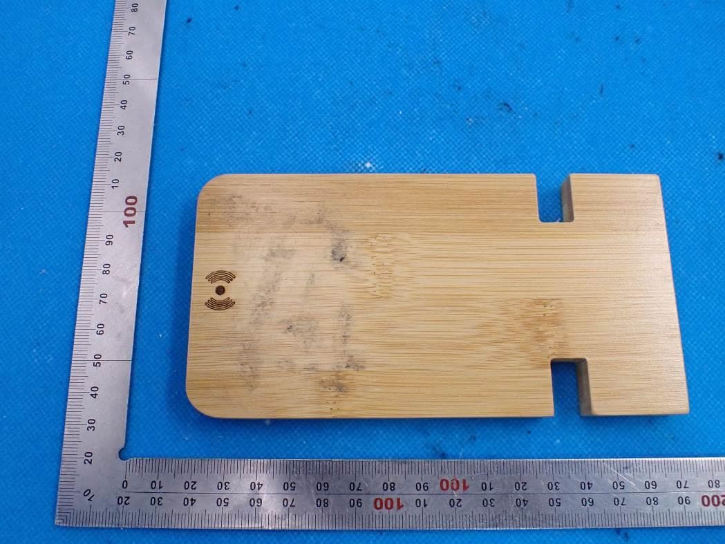
2AJZY-SA329
Jul 07, 2021Bamboo wireless charging phone stand
Equipment Class
DCD - Part 15 Low Power Transmitter Below 1705 kHz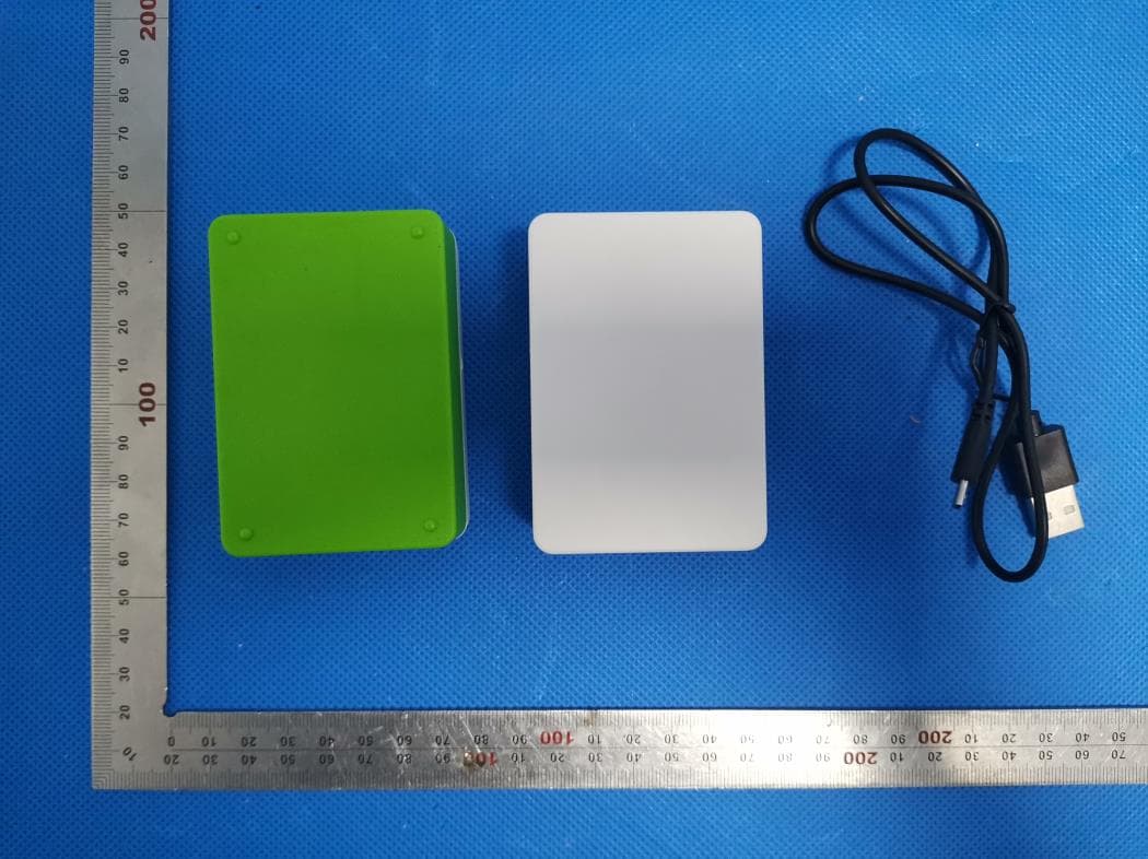
2AJZYSA304
May 04, 20203-in-1 Stowaway Wireless Charging Kit with EarBuds
Equipment Class
DCD - Part 15 Low Power Transmitter Below 1705 kHz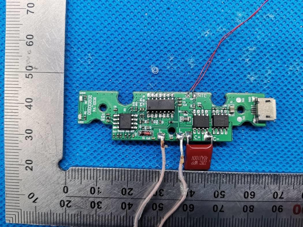
2AJZYSA307
Apr 26, 2020Promo Wireless Charger with Phone Stand
Equipment Class
DCD - Part 15 Low Power Transmitter Below 1705 kHz