2AK29-DS2012Remote Smart Dimmer
Deako Inc.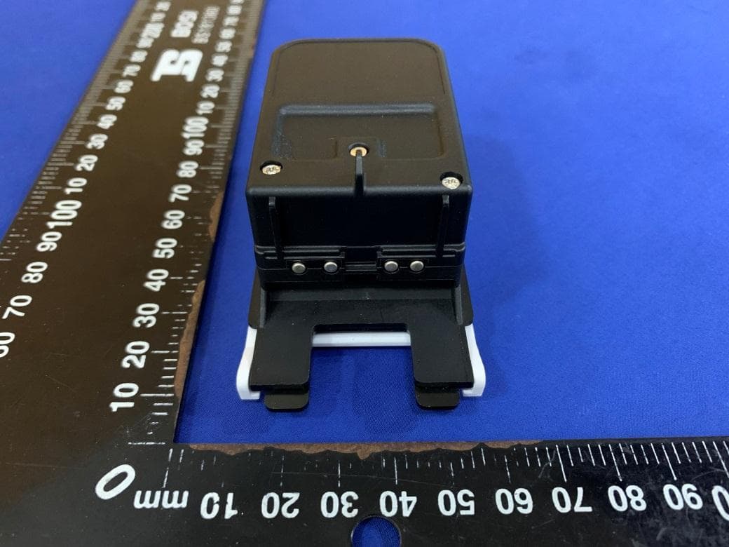
Click to zoom
Application Details
- Equipment Class
- DSS - Part 15 Spread Spectrum Transmitter
- Date of Grant
- Jun 28, 2021
- Application Purpose
- Original Equipment
- Date of Application
- Jun 28, 2021
- Equipment Note
- Remote Smart Dimmer
- Frequency Range
- 2402.00000000 - 2480.00000000
- Company
- Deako Inc.
- Country
- United States
Documents & Files
Document Text
Text extracted from the exhibit documents filed with the FCC. Open a document above to read the original.
Users Manual
Deako Smart Dimmer Single Pole Smart Dimmer Master Smart Dimmer Remote Smart Dimmer Get to know your Deako Switch 22 Main button LED indicators Dimmer control Configure button 33 LED COLORWHAT IT MEANS Blinking greenPowering up Blinking purpleLinking mode Blinking bluePairing mode Blinking whitePairing or Linking LED keyLED key 44 LED COLORWHAT IT MEANS Solid whitePairing or Linking successful Blinking redError occured, try again Solid redFactory resetting 55 How many switches control this light? 66 If two or more switches control this light, TURN TO PAGE 12 2+ switches If one switch controls this light, CONTINUE TO PAGE 8 1 switch 77 Insert a switch 1 Align the blue tab on the backplate with the top of the switch 88 2 While pressing the switch inwards, push in the blue tab 99 Installation complete! Now let’s get smart. 1010 Pairing Control your new smart switch by downloading the Deako App. 1111 What you’ll need 1212 One remote dimmer for each additional switch location 1+ remote dimmer One master dimmer 1x master dimmer 1313 Identify the switch type by looking at the sticker found on the back of your switch. You will either have a Master Smart Dimmer or Remote Smart Dimmer. If you have a different type of switch, go to support.deako.com for more information Switch types 1414 9696669209165087 9696669209165087 1515 1 If there is a switch installed in the backplate you want to upgrade, start by pulling the corner of the faceplate Remove existing dimmerRemove existing dimmer 1616 2 Pull the blue tab outwards to release the switch 1717 3 Locate the powered backplate in the circuit by inserting a Remote Smart Dimmer into a backplate in the circuit Align the blue tab on the backplate with the top of the switch Insert Remote DimmerInsert Remote Dimmer 1818 4 While pressing the switch inwards, push in the blue tab If the backplate is powered, the switch will flash green If switch does not flash green, move to the next location & repeat step 1 1919 5 Wait until the switch stops flashing green, then press & hold the configure button until it flashes purple 2020 6 Move to the next powered backplate, then repeat steps 1-5 for each switch in the circuit until you get to the last switch 2121 7 On the last switch in the circuit, insert the Master Smart Dimmer Insert Master switchInsert Master switch 2222 8 Wait until the switch stops flashing green, then press & hold the configure button until it flashes purple Once all switches in the circuit are flashing purple, continue to step 9 2323 9 Once all switches in the circuit are flashing purple, press & hold the configure button on any switch until it flashes white Once the switches show solid white and turn off, linking is complete 2424 10 To test if they’ve been successfully linked, press each switch to confirm that they control the light Now you’re ready to pair your switches with the Deako App 2525 Troubleshooting • Linking is only required for 3-way and 4-way wiring configurations • If at any point a switch blinks red, factory reset it and try again • To exit linking mode at any point, press & hold the configure button for 10 seconds to factory reset each switch before retrying • If you have dead-end or other nontraditional wiring in your home, you can find wiring and setup instructions at deako.com/wiring 2626 Factory reset Press & hold the configure button for 10 seconds (the LED will be appear solid red). 2727 FCC Statement This device complies with part 15 of the FCC Rules. Operation is subject to the following two conditions: (1) This device may not cause harmful interference, and (2) This device must accept any interference received, including interference that may cause undesired operation. Any Changes or modifications not expressly approved by the party responsible for compliance could void the user's authority to operate the equipment. Note: This equipment has been tested and found to comply with the limits for a Class B digital device, pursuant to part 15 of the FCC Rules. These limits are designed to provide reasonable protection against harmful interference in a residential installation. This equipment generates uses and can radiate radio frequency energy and, if not installed and used in accordance with the instructions, may cause harmful interference to radio communications. However, there is no guarantee that interference will not occur in a particular installation. If this equipment does cause harmful interference to radio or television reception, which can be determined by turning the equipment off and on, the user is encouraged to try to correct the interference by one or more of the following measures: -Reorient or relocate the receiving antenna. -Increase the separation between the equipment and receiver. -Connect the equipment into an outlet on a circuit different from that to which the receiver is connected. -Consult the dealer or an experienced radio/TV technician for help. RF warning: This equipment complies with FCC radiation exposure limits set forth for an uncontrolled environment. This equipment should be installed and operated with minimum distance 20cm between the radiator & your body. IC Statement -English: This device contains licence‐exempt transmitter(s)/receiver(s) that comply with Innovation, Science and Economic Development Canada’s licenceexempt RSS(s). Operation is subject to the following two conditions: (1) This device may not cause harmful interference, and (2) This device must accept any interference received, including interference that may cause undesired operation of the device. The digital apparatus complies with Canadian CAN ICES-3 (B)/NMB-3(B) This device must be installed and operated with a minimum distance of 20 cm between the radiator and user body. -French: L'émetteur/récepteurexempt de licence contenu dans le présent appareil est conforme aux CNR d'Innovation. Sciences et DéveloppementéconomiqueCanada applicables aux appareils radio exempts de licence. L'exploitation est autorisée aux de…
Text truncated - open the document above for the full version.
Cover Letter(s)
Deako Inc. Date: 2021.04.28 Equipment Autorisation Division Federal Communications Commission 7435 Oakland Mills Road Columbia, MD 21046 FCC ID:__2AK29-DS2012 ____ Product Name:__Remote Smart Dimmer ________ Request for Confidentiality Pursuant to Sections 0.457 and 0.459 of the commissions rules, we hereby request that the following documents be held confidential: (List here the documents for which you are seeking confidentiality – for example ...) Schematics Block Diagram Operation Description These materials contain trade secrets and proprietary information and are not customarily released to the public. The public disclosure of this information might be harmful to the company and provide unjustified benefits to our competitors. Signature: Name: Derek Richardson Company: Deako Inc. Address: 4201 Roosevelt Way NE Suite 100 Seattle WA 98105 United States Phone: 1-844-67-33256 Fax: / Mail: [email protected]
External Photos
CTC Laboratories, Inc. 1-2/F., Building 2, Jiaquan Building, Guanlan High-Tech Park, Shenzhen, Guangdong, China Tel: +86-755-27521059 Fax: +86-755-27521011 Http://www.sz-ctc.org.cn External Photographs
ID Label/Location Info
CTC Laboratories, Inc. 2/F., Building 1 and 1-2/F., Building 2, Jiaquan Building, Guanlan High-Tech Park, Longhua District, Shenzhen, Guangdong, China Tel: +86-755-27521059 Fax: +86-755-27521011 Http://www.sz-ctc.org.cn Label Label Location 1.
Internal Photos
CTC Laboratories, Inc. 1-2/F., Building 2, Jiaquan Building, Guanlan High-Tech Park, Shenzhen, Guangdong, China Tel: +86-755-27521059 Fax: +86-755-27521011 Http://www.sz-ctc.org.cn Internal Photographs BT&WiFi ANT
RF Exposure Info
CTC Laboratories, Inc. 1-2/F., Building 2, Jiaquan Building, Guanlan High-Tech Park, Shenzhen, Guangdong, China Tel: +86-755-27521059 Fax: +86-755-27521011 Http://www.sz-ctc.org.cn CTC Laboratories, Inc. 1-2/F., Building 2, Jiaquan Building, Guanlan High-Tech Park, Shenzhen, Guangdong, China Tel.: (86)755-27521059 Fax: (86)755-27521011 Http://www.sz-ctc.org.cn For anti-fake verification, please visit the official website of Certification and Accreditation Administration of the People’s Republic of China : yz.cnca.cn Maximum Permissible Exposure Evaluation FCC ID: 2AK29-DS2012 According to FCC 1.1310: The criteria listed in the following table shall be used to evaluate the environment impact of human exposure to radio frequency (RF) Radiation as specified in §1.1307(b) EUT Specification: Product Name Remote Smart Dimmer Trade Mark / Model/Type reference DS2012 Listed Model(s) / Model Difference / Frequency band (Operating) BT: 2.402GHz ~ 2.480GHz BLE: 2.402GHz ~ 2.480GHz WLAN: 2.412GHz ~ 2.462GHz RLAN: 5.180GHz ~ 5.240GHz RLAN: 5.745GHz ~ 5.825GHz Device category Portable (<5mm separation) Mobile (>20cm separation) fixed (>20cm separation) Others ___ Exposure classification Occupational/Controlled exposure (S=5mW/cm2) General Population/Uncontrolled exposure (S=1mW/cm2) Antenna diversity Single antenna Multiple antenna Tx diversity Rx diversity Tx/Rx diversity Antenna gain (Max) 2dBi Evaluation applied MPE Evaluation SAR Evaluation Limits for Maximum Permissible Exposure (MPE) Frequency Range(MHz) Electric Field Strength(V/m) Magnetic Field Strength(A/m) Power Density(mW/cm 2 ) Average Time (A) Limits for Occupational/Control Exposures 300-1500 -- -- F/300 6 1500-100000 -- -- 5 6 (B) Limits for General Population/Uncontrol Exposures 300-1500 -- -- F/1500 6 1500-100000 -- -- 1 30 Page 2 of 3 Report No.: CTC20210160E04 CTC Laboratories, Inc. 1-2/F., Building 2, Jiaquan Building, Guanlan High-Tech Park, Shenzhen, Guangdong, China Tel.: (86)755-27521059 Fax: (86)755-27521011 Http://www.sz-ctc.org.cn For anti-fake verification, please visit the official website of Certification and Accreditation Administration of the People’s Republic of China : yz.cnca.cn Friis transmission formula: Pd=(Pout*G)\(4*pi*R 2 ) Where Pd= Power density in mW/cm 2 Pout= output power to antenna in mW G= gain of antenna in linear scale Pi= 3.1416 R= distance between observation point and center of the radiator in cm Pd the limit of MPE 1mW/cm 2 . If we know the maximum gain of the antenna and total power input to the antenna, through the calculation, we will know the distance where the MPE limit is reached. Measurement Result BLE Type Channel frequency (MHz) Max. Measured Power (dBm) Tune up tolerance (dBm) Max. Tune up Power (dBm) Antenna Gain (dBi) Power density at 20cm (mW/cm 2 ) Power density Limits (mW/cm 2 ) GFSK 2402 7.20 7±1 8 2 0.001655 1 2440 7.29 7±1 8 2 0.001689 1 2480 7.39 7±1 8 2 0.001729 1 BR/ EDR Type Channel frequency (MHz) Max. Measured Power (dBm) Tune up tolerance (dBm) Max. Tune up Power (dBm) Antenna Gain (dBi) Power density at 20cm (mW/cm 2 ) Power density Limits (mW/cm 2 ) GFSK 2402 7.45 7±1 8 2 0.001753 1 2441 7.59 7±1 8 2 0.001810 1 2480 7.65 7±1 8 2 0.001835 1 π/4-DQPSK 2402 6.04 6±1 7 2 0.001267 1 2441 6.23 6±1 7 2 0.001324 1 2480 6.42 6±1 7 2 0.001383 1 8-DPSK 2402 6.64 6±1 7 2 0.001455 1 2441 6.62 6±1 7 2 0.001448 1 2480 6.83 6±1 7 2 0.001520 1 Page 3 of 3 Report No.: CTC20210160E04 CTC Laboratories, Inc. 1-2/F., Building 2, Jiaquan Building, Guanlan High-Tech Park, Shenzhen, Guangdong, China Tel.: (86)755-27521059 Fax: (86)755-27521011 Http://www.sz-ctc.org.cn For anti-fake verification, please visit the official website of Certification and Accreditation Administration of the People’s Republic of China : yz.cnca.cn WLAN Type Channel frequency (MHz) Max. Measured Power (dBm) Tune up tolerance (dBm) Max. Tune up Power (dBm) Antenna Gain (dBi) Power density at 20cm (mW/cm 2 ) Power density Limits (mW/cm 2 ) 802.11b 2412 17.66 17±1 18 2 0.018397 1 2437 17.43 17±1 18 2 0.017448 1 2462 17.52 17±1 18 2 0.017813 1 802.11g 2412 18.54 18±1 19 2 0.022529 1 2437 18.53 18±1 19 2 0.022477 1 2462 19.43 19±1 20 2 0.027653 1 802.11n (HT20) 2412 18.03 18±1 19 2 0.020033 1 2437 18.04 18±1 19 2 0.020079 1 2462 18.80 18±1 19 2 0.023919 1 802.11n (HT40) 2422 17.30 17±1 18 2 0.016933 1 2437 16.86 16±1 17 2 0.015302 1 2452 17.03 17±1 18 2 0.015913 1 The WLAN or Bluetooth can transmit simultaneously. WLAN Power density at 20cm (mW/cm 2 ) Bluetooth Power density at 20cm (mW/cm 2 ) Total Power density at 20cm (mW/cm 2 ) Power density Limits (mW/cm 2 ) 0.027653 0.001835 0.029488 1 Note: For a more detailed features description, please refer to the RF Test Report. **********************THE END**********************
Test Report
CTC Laboratories, Inc. 1-2/F., Building 2, Jiaquan Building, Guanlan High-Tech Park, Shenzhen, Guangdong, China Tel: +86-755-27521059 Fax: +86-755-27521011 Http://www.sz-ctc.org.cn TEST REPORT Report No. ··························: CTC20210160E02 FCC ID································: 2AK29-DS2012 IC.......................................: 22393-DS2012 Applicant····························: Deako Inc. Address·······························: 4201 Roosevelt Way NE Suite 100 Seattle WA 98105 United States Manufacturer·························: Deako Inc. Address·······························: 4201 Roosevelt Way NE Suite 100 Seattle WA 98105 United States Product Name······················: Remote Smart Dimmer Trade Mark···························: / Model/Type reference·············: DS2012 Listed Model(s) ·····················: / Standard·····························: FCC CFR Title 47 Part 15 Subpart C Section 15.247 RSS 247 Issue 2 Date of receipt of test sample...: Feb. 23, 2021 Date of testing.......................: Apr. 12, 2021 to Apr. 28, 2021 Date of issue.........................: Apr. 28, 2021 Result.................................: PASS Compiled by: (Printed name+signature) Jim Jiang Supervised by: (Printed name+signature) Miller Ma Approved by: (Printed name+signature) Walter Chen $英文检测章$ $Walter$ Testing Laboratory Name......: CTC Laboratories, Inc. Address...............................: 1-2/F., Building 2, Jiaquan Building, Guanlan High-Tech Park, Shenzhen, Guangdong, China This test report may be duplicated completely for legal use with the approval of the applicant. It should not be reproduced except in full, without the written approval of our laboratory. The client should not use it to claim product endorsement by CTC. The test results in the report only apply to the tested sample. The test report shall be invalid without all the signatures of testing engineers, reviewer and approver. Any objections must be raised to CTC within 15 days since the date when the report is received. It will not be taken into consideration beyond this limit. The test report merely correspond to the test sample. Page 2 of 89 Report No.: CTC20210160E02 CTC Laboratories, Inc. 1-2/F., Building 2, Jiaquan Building, Guanlan High-Tech Park, Shenzhen, Guangdong, China Tel.: (86)755-27521059 Fax: (86)755-27521011 Http://www.sz-ctc.org.cn For anti-fake verification, please visit the official website of Certification and Ac- creditation Administration of the People’s Republic of China : yz.cnca.cn Table of Contents Page 1. TEST SUMMARY ....................................................................................................................................................... 3 1.1. TEST STANDARDS .......................................................................................................................................................... 3 1.2. REPORT VERSION ......................................................................................................................................................... 3 1.3. TEST DESCRIPTION ........................................................................................................................................................ 3 1.4. TEST FACILITY .............................................................................................................................................................. 4 1.5. MEASUREMENT UNCERTAINTY ........................................................................................................................................ 4 1.6. ENVIRONMENTAL CONDITIONS ........................................................................................................................................ 5 2. GENERAL INFORMATION .......................................................................................................................................... 6 2.1. CLIENT INFORMATION ................................................................................................................................................... 6 2.2. GENERAL DESCRIPTION OF EUT ...................................................................................................................................... 6 2.3. ACCESSORY EQUIPMENT INFORMATION ............................................................................................................................ 7 2.4. OPERATION STATE ........................................................................................................................................................ 8 2.5. MEASUREMENT INSTRUMENTS LIST ................................................................................................................................. 9 3. TEST ITEM AND RESULTS ........................................................................................................................................ 11 3.1. CONDUCTED EMISSION ................................................................................................................................................ 11 3.2. RADIATED EMISSION ................................................................................................................................................... 14 3.3. BAND EDGE EMISSIONS (RADIATED) .............................................................................................................................. 37 3.4. BAND EDGE AND SPURIOUS EMISSIONS (CONDUCTED) ...................................................................................................... 50 3.5. BANDWIDTH .............................................................................................................................................................. 65 3.6. CHANNEL SEPARATION................................................................................................................................................. 73 3.7. NUMBER OF HOPPING CHANNEL ....…
Text truncated - open the document above for the full version.
Test Report
Page 65 of 89 Report No.: CTC20210160E02 CTC Laboratories, Inc. 1-2/F., Building 2, Jiaquan Building, Guanlan High-Tech Park, Shenzhen, Guangdong, China Tel.: (86)755-27521059 Fax: (86)755-27521011 Http://www.sz-ctc.org.cn For anti-fake verification, please visit the official website of Certification and Ac- creditation Administration of the People’s Republic of China : yz.cnca.cn 3.5. Bandwidth Limit N/A Test Configuration Test Procedure 1. The EUT was directly connected to the spectrum analyzer and antenna output port as show in the block diagram above. 2. OCB and 20dB Spectrum Setting: (1) Set RBW = 1% ~ 5% occupied bandwidth. (2) Set the video bandwidth (VBW) ≥ 3 RBW. (3) Detector = Peak. (4) Trace mode = Max hold. (5) Sweep = Auto couple. Note: The EUT was set to continuously transmitting in each mode and low, Middle and high channel for the test. Test Mode Please refer to the clause 2.4. Test Result Test Mode Frequency (MHz) 20dB EBW[MHz] FL[MHz] FH[MHz] 20dB Bandwidth *2/3 (kHz) Verdict GFSK 2402 0.948 2401.517 2402.465 632.00 PASS 2441 0.945 2440.517 2441.462 630.00 PASS 2480 0.945 2479.517 2480.462 630.00 PASS π/4-DQPSK 2402 1.326 2401.319 2402.645 884.00 PASS 2441 1.323 2440.322 2441.645 882.00 PASS 2480 1.323 2479.322 2480.645 882.00 PASS 8-DPSK 2402 1.308 2401.331 2402.639 872.00 PASS 2441 1.308 2440.331 2441.639 872.00 PASS 2480 1.308 2479.331 2480.639 872.00 PASS Page 66 of 89 Report No.: CTC20210160E02 CTC Laboratories, Inc. 1-2/F., Building 2, Jiaquan Building, Guanlan High-Tech Park, Shenzhen, Guangdong, China Tel.: (86)755-27521059 Fax: (86)755-27521011 Http://www.sz-ctc.org.cn For anti-fake verification, please visit the official website of Certification and Ac- creditation Administration of the People’s Republic of China : yz.cnca.cn DH5_Ant1_2402 DH5_Ant1_2441 DH5_Ant1_2480 Page 67 of 89 Report No.: CTC20210160E02 CTC Laboratories, Inc. 1-2/F., Building 2, Jiaquan Building, Guanlan High-Tech Park, Shenzhen, Guangdong, China Tel.: (86)755-27521059 Fax: (86)755-27521011 Http://www.sz-ctc.org.cn For anti-fake verification, please visit the official website of Certification and Ac- creditation Administration of the People’s Republic of China : yz.cnca.cn 2DH5_Ant1_2402 2DH5_Ant1_2441 2DH5_Ant1_2480 Page 68 of 89 Report No.: CTC20210160E02 CTC Laboratories, Inc. 1-2/F., Building 2, Jiaquan Building, Guanlan High-Tech Park, Shenzhen, Guangdong, China Tel.: (86)755-27521059 Fax: (86)755-27521011 Http://www.sz-ctc.org.cn For anti-fake verification, please visit the official website of Certification and Ac- creditation Administration of the People’s Republic of China : yz.cnca.cn 3DH5_Ant1_2402 3DH5_Ant1_2441 3DH5_Ant1_2480 Page 69 of 89 Report No.: CTC20210160E02 CTC Laboratories, Inc. 1-2/F., Building 2, Jiaquan Building, Guanlan High-Tech Park, Shenzhen, Guangdong, China Tel.: (86)755-27521059 Fax: (86)755-27521011 Http://www.sz-ctc.org.cn For anti-fake verification, please visit the official website of Certification and Ac- creditation Administration of the People’s Republic of China : yz.cnca.cn Test Result Test Mode Antenna Frequency (MHz) OCB [MHz] FL[MHz] FH[MHz] Verdict DH5 Ant1 2402 0.827 2401.565 2402.393 PASS 2441 0.830 2440.562 2441.393 PASS 2480 0.830 2479.562 2480.393 PASS 2DH5 Ant1 2402 1.175 2401.395 2402.569 PASS 2441 1.175 2440.395 2441.569 PASS 2480 1.178 2479.395 2480.572 PASS 3DH5 Ant1 2402 1.175 2401.398 2402.572 PASS 2441 1.175 2440.398 2441.572 PASS 2480 1.175 2479.398 2480.572 PASS DH5_Ant1_2402 DH5_Ant1_2441 Page 70 of 89 Report No.: CTC20210160E02 CTC Laboratories, Inc. 1-2/F., Building 2, Jiaquan Building, Guanlan High-Tech Park, Shenzhen, Guangdong, China Tel.: (86)755-27521059 Fax: (86)755-27521011 Http://www.sz-ctc.org.cn For anti-fake verification, please visit the official website of Certification and Ac- creditation Administration of the People’s Republic of China : yz.cnca.cn DH5_Ant1_2480 2DH5_Ant1_2402 2DH5_Ant1_2441 Page 71 of 89 Report No.: CTC20210160E02 CTC Laboratories, Inc. 1-2/F., Building 2, Jiaquan Building, Guanlan High-Tech Park, Shenzhen, Guangdong, China Tel.: (86)755-27521059 Fax: (86)755-27521011 Http://www.sz-ctc.org.cn For anti-fake verification, please visit the official website of Certification and Ac- creditation Administration of the People’s Republic of China : yz.cnca.cn 2DH5_Ant1_2480 3DH5_Ant1_2402 3DH5_Ant1_2441 Page 72 of 89 Report No.: CTC20210160E02 CTC Laboratories, Inc. 1-2/F., Building 2, Jiaquan Building, Guanlan High-Tech Park, Shenzhen, Guangdong, China Tel.: (86)755-27521059 Fax: (86)755-27521011 Http://www.sz-ctc.org.cn For anti-fake verification, please visit the official website of Certification and Ac- creditation Administration of the People’s Republic of China : yz.cnca.cn 3DH5_Ant1_2480 Page 73 of 89 Report No.: CTC20210160E02 CTC Laboratories, Inc. 1-2/F., Building 2, Jiaquan Building, Guanlan High-Tech Park, Shenzhen, Guangdong, China Tel.: (86)755-27521059 Fax: (86)755-27521011 Http://www.sz-ctc.org.cn For anti-fake verification, please visit the official website of Certification and Ac- creditation Administration of the People’s Republic of China : yz.cnca.cn 3.6. Channel Separation Limit FCC CFR Title 47 Part 15 Subpart C Section 15.247 (a)(1)/ RSS-247 5.1 b : Test Item Limit Frequency Range(MHz) Channel Separation >25KHz or >two-thirds of the 20 dB bandwidth Which is greater 2400~2483.5 Test Configuration Test Procedure 1. The EUT was directly connected to the spectrum analyzer and antenna output port as show in the block diagram above. 2. Spectrum Setting: (1) Set RBW = 100 kHz. (2) Set the video bandwidth (VBW) ≥ 3 RBW. (3) Detector = Peak. (4) Trace mode = Max hold. (5) Sweep = Auto couple. Test Mode Please refer to the clause 2.4. Test Result Test Mode Frequency(MHz) Result[MHz] Limit[MHz] Verdict GFSK Hop_2402 0.991 ≥632.00 PASS Hop_2441 1.022 ≥630.00 PASS Hop_2480 1.047 ≥630.00 PASS π/4-DQPSK Hop_2402 1.004 ≥884.00 PASS Hop_2441 1.004 ≥882.00 PASS Hop_2480 1.004 ≥882.00 PASS 8-DPSK Ho…
Text truncated - open the document above for the full version.
Test Setup Photos
CTC Laboratories, Inc. 1-2/F., Building 2, Jiaquan Building, Guanlan High-Tech Park, Shenzhen, Guangdong, China Tel: +86-755-27521059 Fax: +86-755-27521011 Http://www.sz-ctc.org.cn Radiated Measurements 30-1000MHz Above 1GHz Conducted Measurements
Contact Information
Applicant
Derek Richardson(CEO)
Test Firm
CTC Laboratories, Inc.Totti Zhao
[email protected]+8675527521059
Technical Specifications
| # | Rule Parts | Frequency Range | Power Output |
|---|---|---|---|
| 1 | 15C | 2.40 GHz - 2.48 GHz | 5.80 mW |
Other Applications from Deako Inc.
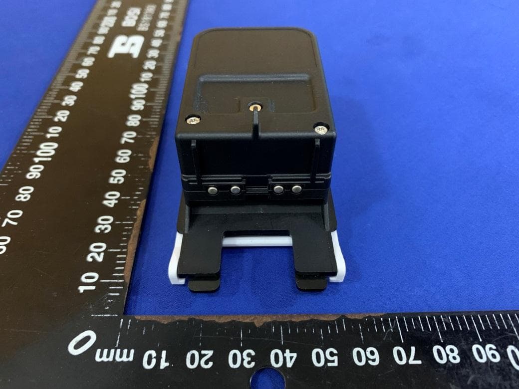
2AK29-DS2011
Jun 28, 2021Master Smart Dimmer
Equipment Class
DSS - Part 15 Spread Spectrum Transmitter2AK29-DS2010
Jun 25, 2021Single Pole Smart Dimmer
Equipment Class
DTS - Digital Transmission System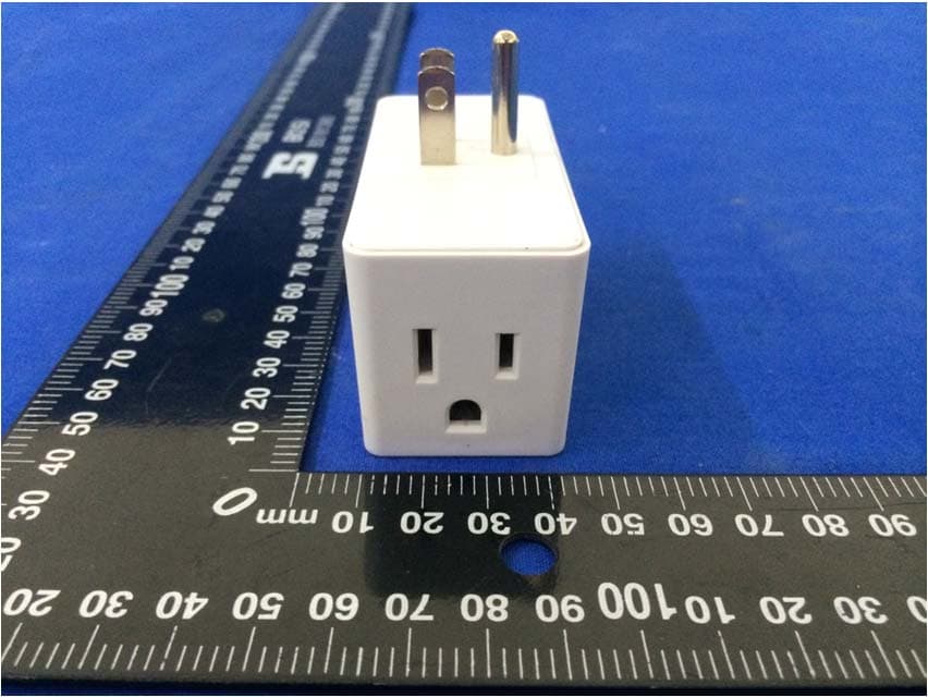
2AK29-DS2002
Mar 02, 2021Smart Plug
Equipment Class
DTS - Digital Transmission System