2AK2OLSSWIRSDKLS SWIR
STRATIO, INC.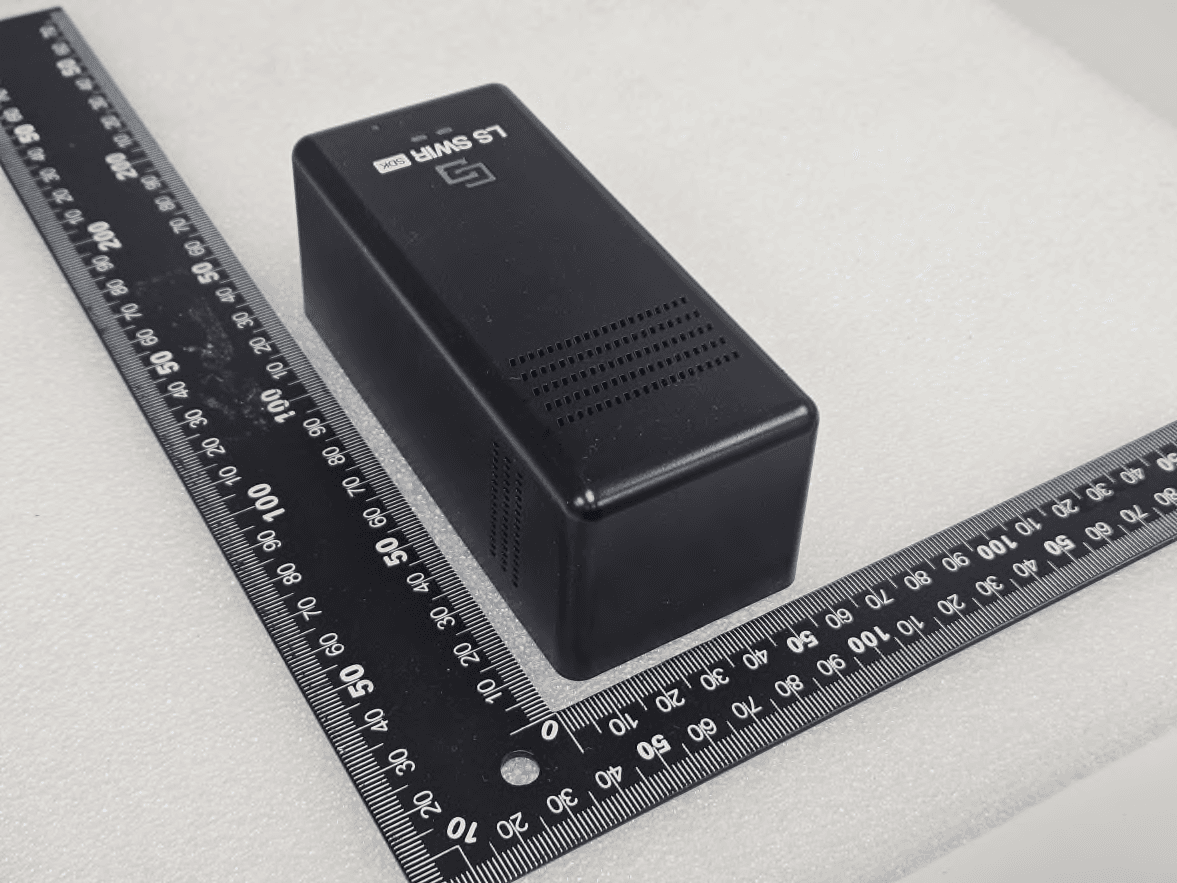
Click to zoom
Application Details
- Equipment Class
- DTS - Digital Transmission System
- Date of Grant
- Dec 22, 2025
- Application Purpose
- Original Equipment
- Equipment Note
- LS SWIR
- Frequency Range
- 2402.00000000 - 2480.00000000
- Company
- STRATIO, INC.
- Country
- South Korea
Documents & Files
Document Text
Text extracted from the exhibit documents filed with the FCC. Open a document above to read the original.
Users Manual
LS SWIR SDK SWIR Spectral Sensor USER GUIDE ⓒ 2025 STRATIO, INC. All rights reserved. Item Spec Wavelength Range 1225 nm - 1625 nm Number of Channels 8 Bandwidth 50 nm / channel SNR 1000 : 1 Sample Coverage (diameter of collected light beam) Φ 10 mm Max Power 5.5 W Battery Life > 2,000 scans Battery Type Rechargeable Li-ion 18650 batteries Battery Charging Method USB-C connector Battery Charging Time 5 hours Connectivity Bluetooth Low Energy (BLE) V5.2, USB Operating Temperature -5°C to +40 °C Size 49 x 56 x 128 mm Weight 260 g Product Specifications Device Components Power Switch SCAN Button ON/OFF LED Status LED Battery LED SCAN LED 1. Preparing the Device Turn on the power switch on the side of the LS SWIR SDK device. After the switch is turned on, the green ON/OFF LED will blink for up to 12 seconds while the device initializes. When the device is ready, the green LED on the top of the device will light up. 2. Running the Program ① Install the Program: Run the provided LS SWIR SDK installer file and follow the on-screen instructions to install the program. ② Launch the program: After installation, find LS SWIR SDK in the Start menu or on the desktop, and double-click to launch it 3. Connecting the Device ① Click the Device tab in the menu on the left side of the screen. ② Connect the LS SWIR SDK device to your PC with a USB cable, then switch the device power to ON. ③ The detected device will appear under the Bluetooth and USB sections. ④ Select the connection type and click Connect button. Note For Bluetooth connection, ensure your PC’s Bluetooth is enabled. 4. Create a Project and Sample 4-1. Create a New Project ① Go to the Project tab. ② Click the New button at the top of the screen to open the New Project window. ③ Select a Scan Mode. This setting is permanent for the project. - Quick: Fast scan, lower accuracy. - Standard: Balanced speed and accuracy. - Precise: Slowest scan, highest accuracy. ④ Enter a project name and click the Create button to create the project. Project files are saved in "My Documents/LinkSquare/Projects/(Project Name).proj". Getting Started 4-2. Adding a New Sample ① In the Project screen, click the + button under Samples. ② In the New Sample window, enter sample details. - Name: Enter the material name. - Description (Optional): Add a reference note. - Choose file... (Optional): Upload an icon (512 x 512 pixels recommended). - Regression Value: This is an advanced feature; leave it blank for classification tasks. - Color: Assign a chart color for the sample. ③ Click the OK to create the sample. ④ Repeat for all required samples. 5. Collecting Scan Data Collect spectrum data for each sample. ① Go to the Data Collection tab. ② Select the sample corresponding to the material you want to scan. ③ Place the device’s sensor against the material, and click the SCAN button on the screen or press the physical button on the side of the device. ④ When the scan proceeds, the scan result will appear in the Spectral Graph area. Note The SCAN button is only active when the device is connected and a sample is selected. 6. Training a Model Using the collected data, you can train a model to distinguish between the samples. ① Go to the Training tab. ② Select a Training Algorithm from the dropdown menu at the top. ③ In the Training Data panel, choose the samples to be included in the training process. ④ (Optional) Adjust algorithm-specific hyperparameters in the Hyperparameters section. ⑤ Click Start Training at the top right, and the training results will be displayed in the Result area. ⑥ If the model performance meets your expectations, click the Save Result to store the trained model. If you do not click the Save Result, the trained model will not be saved. Note (Training can only begin if both of the following conditions are met.) √ Each sample must contain at least 10 scans. √ The number of scans per sample must be greater than the total number of samples. 7. Infrared AI ① Go to the Infrared AI tab to test the trained model. ② From the Select AI Model dropdown menu, choose the model you saved. ③ Press the SCAN button, and the classification result and spectrum chart will appear on the screen. Notice To proceed with a scan, the device must be connected. ⚫ 9-hour 1,250 Scan Test (Repeatability and SNR) A. Result Raw Data vs. Corrected Data (Preprocessing: Standard) : After applying sensor-specific correction (standard preprocessing), the variation between repeated measurements is significantly reduced. < Figure: 1,250 scans; Raw Data (left) vs. Corrected Data (right), Sample: Cotton, LS SWIR SDK Serial #0016 > B. Channel Drift in Raw Data (1,250 Scans) : Even during extended operation, raw data shows minimal drift across channels. < Channel drift results over 1,250 scans – Raw Data> Device Performance Data FCC Compliance Statement This device complies with part 15 of the FCC rules. Operation is subject to the following two conditions: (1) This device may not cause harmful interference, and (2) this device must accept any interference received, including interference that may cause undesired operation. FCC Interference Statement This equipment has been tested and found to comply with the limits for a Class B digital device, pursuant to part 15 of the FCC Rules. These limits are designed to provide reasonable protection against harmful interference in a residential installation. This equipment generates, uses and can radiate radio frequency energy and, if not installed and used in accordance with the instructions, may cause harmful interference to radio communications. However, there is no guarantee that interference will not occur in a particular installation. If this equipment does cause harmful interference to radio or television reception, which can be determined by turning the equipment off and on, the user is encouraged to correct the interference by one of the following measures: • Reorient or relocate the receiving antenna. • Increase the separation between the equ…
Text truncated - open the document above for the full version.
Attestation Statements
STRATIO, INC. B-911, 43, Changeop-ro, Sujeong-gu, Seongnam-si, Gyeonggi-do, South korea Tel: +1-650-796-7456 Rev 1/26/2023 Federal Communications Commission Authorization and Evaluation Division 7435 Oakland Mills Road Columbia, MD 21046 USA Date: December 03, 2025 Ref: Attestation Statements Part 2.911(d)(7) Filing FCC ID : 2AK2OLSSWIRSDK Applicant FRN: 0037717345 [STRATIO, INC.] (“the applicant”) certifies that, as of the date of the filing of the application, [STRATIO, INC.] is our designated U.S. agent for service of process for the above referenced FCC ID. [STRATIO, INC.] accepts to maintain an agent for no less than one year after the grantee has terminated all marketing and importation or the conclusion of any Commission-related proceeding involving the equipment. [STRATIO, INC.] accepts, as of the date of the filing of the application, the obligation of the designated U.S. agent for service of process for the above referenced FCC ID. Designated U.S. Agent Information: Name: STRATIO, INC. U.S. Agent FRN: 0026200592 Address: 2211 Fortune Dr. Suite A San Jose CA 95131 United States Contact Person: Mr JAE HYUNG LEE Tel.: +1-650-796-7456 Email: [email protected] Sincerely, STRATIO, INC. STRATIO, INC. Head of Operations / hyejin choi CEO / JAEHYUNG LEE
Attestation Statements
STRATIO, INC. B-911, 43, Changeop-ro, Sujeong-gu, Seongnam-si, Gyeonggi-do, South korea Tel: +1-650-796-7456 Rev 1/26/2023 Federal Communications Commission Authorization and Evaluation Division 7435 Oakland Mills Road Columbia, MD 21046 USA Date: December 03, 2025 Ref: Attestation Statements Part 2.911(d)(5)(i) Filing FCC ID : 2AK2OLSSWIRSDK [STRATIO, INC.] (“the applicant”) certifies that the equipment for which authorization is sought is not “covered” equipment prohibited from receiving an equipment authorization pursuant to section 2.903 of the FCC rules. [STRATIO, INC.] (“the applicant”) certifies that the equipment for which authorization is sought does not include cybersecurity or anti-virus software produced or provided by Kaspersky Lab, Inc. or any of its successors and assignees, including equipment with integrated Kaspersky Lab, Inc. (or any of its successors and assignees) cybersecurity or anti-virus software pursuant to DA-24-886 and KDB 986446 D01 Covered Equipment Guidance section B(2a). Device is inherently compliant based on hardware limitations or software controls. or A Software Bill of Materials (SBOM) is provided to the TCB for review, and The end-user or third parties cannot install additional software on this device. Sincerely, Head of Operations / hyejin choi STRATIO, INC. STRATIO, INC. B-911, 43, Changeop-ro, Sujeong-gu, Seongnam-si, Gyeonggi-do, South korea Tel: +1-650-796-7456 Rev 1/26/2023 Federal Communications Commission Authorization and Evaluation Division 7435 Oakland Mills Road Columbia, MD 21046 USA Date: December 03, 2025 Ref: Attestation Statements Part 2.911(d)(5)(ii) Filing FCC ID : 2AK2OLSSWIRSDK [STRATIO, INC.] (“the applicant”) certifies that, as of the date of the filing of the application, the applicant is not identified on the Covered List (as a specifically named entity or any of its subsidiaries or affiliates) as an entity producing “covered” equipment. Sincerely, Head of Operations / hyejin choi STRATIO, INC.
Cover Letter(s)
STRATIO, INC. B-911, 43, Changeop-ro, Sujeong-gu, Seongnam-si, Gyeonggi-do, South korea Tel: +1-650-796-7456 Date: December 03, 2025 Federal Communications Commission 7435 Oakland Mills Road Columbia MD 21046 Confidentiality Request regarding application for certification of FCC ID : 2AK2OLSSWIRSDK Pursuant to Sections 0.457 and 0.459 of the Commission’s Rules and IC regulation, we hereby request confidential treatment of information accompanying this application as outlined below: PERMANENT Exhibit Type File Name Part List Part List.pdf Schematics Diagram(s) Schematic.pdf Operation description Operation description.pdf Block diagram Block diagram.pdf And the above materials contain trade secrets and proprietary information not customarily released to the public. The public disclosure of these materials may be harmful to the applicant and provide unjustified benefits to its competitors. The applicant understands that pursuant to Section 0.457 of the Rules, disclosure of this application and all accompanying documentation will not be made before the date of the Grant for this application. Sincerely, Head of Operations / hyejin choi STRATIO, INC.
Cover Letter(s)
STRATIO, INC. B-911, 43, Changeop-ro, Sujeong-gu, Seongnam-si, Gyeonggi-do, South korea Tel: +1-650-796-7456 Date: December 03, 2025 Federal Communications Commission 7435 Oakland Mills Road Columbia MD 21046 FCC ID : 2AK2OLSSWIRSDK To whom it may concern: I, the undersigned, hereby authorize Young-Jin, Lee of KES Co., Ltd. and hereafter referred to as KES Co., Ltd., to act on our behalf in all manners relating to application for equipment authorization, including signing of all documents relating to these matters. Any and all acts carried out by Young-Jin, Lee of KES Co., Ltd. on our behalf shall have the same effect as acts of our own. I, the undersigned, hereby certify that we are not subject to a denial of federal benefits, that includes FCC benefits, pursuant to Section 5301 of the Anti-Drug Abuse Act of 1988, 21 U.S.C. 853(a). In authorizing KES Co., Ltd. as our agent, we still recognize that we are responsible to: a) comply with the relevant provisions of the certification program; b) make all necessary arrangements for the conduct of the evaluation, including provision for examining documentation and access to all areas, records (including internal audit reports) and personnel for the purposes of evaluation (e.g. testing, inspection, assessment, surveillance, reassessment) and resolution of complaints; c) make claims regarding certification only in respect of the scope for which certification has been granted; d) do not use our product certification in such a manner as to bring the Certification Division into disrepute and not make any statement regarding our product certification which the Certification Division may consider misleading or unauthorized; e) upon suspension or cancellation of certification, discontinue use of all advertising matter that contains any reference thereto and return any certification documents as required by the Certification Division; f) use certification only to indicate the products are certified as being in conformity with specified standards; STRATIO, INC. B-911, 43, Changeop-ro, Sujeong-gu, Seongnam-si, Gyeonggi-do, South korea Tel: +1-650-796-7456 g) endeavor to ensure that no certificate or report nor any part thereof is used in a misleading manner; h) ensure that any reference to our product certification in communication media such as documents, brochures or advertising, complies with the requirements of the Certification Division; i) keep a record of all complaints made known to the us relating to the product’s compliance with requirements of the relevant standard and to make these records available to the Certification Division when requested; j) take appropriate action with respect to such complaints and any deficiencies found in products or services that affect compliance with the requirements for certification; k) document the actions taken. This authorization is valid until further written notice from the applicant. Sincerely Yours, Head of Operations / hyejin choi STRATIO, INC. REMARK: 1. This authorization letter will be sent along with your application when filing with the Certification Division. 2. Please follow the format and type it on company letterhead and send original to us. 3. Authorized signature must be in agreement with grantee code contact in FCC database.
External Photos
FCC ID : 2AK2OLSSWIRSDKPage 1 of 2 External photos FCC ID : 2AK2OLSSWIRSDKPage 2 of 2 Blank
ID Label/Location Info
FCC ID : 2AK2OLSSWIRSDKPage 1 of 1 Label Location Label The device is so small that it is not practicable to place the statement specified under 15.19 statement request, the information required by this paragraph shall be placed in a prominent location in the User’s Manual.
Internal Photos
FCC ID : 2AK2OLSSWIRSDK Page 1 of 2 Internal photos FCC ID : 2AK2OLSSWIRSDK Page 2 of 2 PCB Antenna Blank
RF Exposure Info
FCC ID : 2AK2OLSSWIRSDKPage 1 of 1 RF exposure FCC ID : 2AK2OLSSWIRSDK According to 447498 D01 General RF Exposure Guidance v06 The 1-g and 10-g SAR test exclusion thresholds for 100㎒to 6㎓ at test separation distances ≤ 50 mm are determined by: [(max. power of channel, including tune-up tolerance, mW)/(min. test separation distance, mm)] ·[√f(㎓)] ≤ 3.0 for 1-g SAR and ≤ 7.5 for 10-g extremity SAR, Where; f(㎓) is the RF channel transmit frequency in㎓ Power and distance are rounded to the nearest㎽andmmbefore calculation The result is rounded to one decimal place for comparison Results Mode Frequency (㎓) Distance (mm) Maxtune-up power (㏈m) Calculation value Exclusion Threshold (㏈m)(㎽) LE 1 Mbps 2.402 ~ 2.4805 -4.00.3980.125≤3.0 LE 2 Mbps-4.00.3980.125≤3.0
Test Report
TEST REPORT Report No. : KES-RF250740-R1 Page1/41 KES Co., Ltd. #3002, #3503, #3701, 40, Simin-daero365beon-gil, Dongan-gu, Anyang-si,Gyeonggi-do, 14057, Republic ofKorea Tel : +82-31-425-6200, Fax : +82-31-341-3838 KES-QP16-F01(00-23-01-01)KES Co., Ltd. You can check the authenticity of this test report on our website (www.kes.co.kr). FCC TEST REPORT 1. Client ○ Name : STRATIO, INC. ○ Address : B-911, 43, Changeop-ro, Sujeong-gu, Seongnam-si, Gyeonggi-do, South korea 2. Sample Description ○ Product item : LS SWIR ○ Model name : LS SWIR SDK ○ Manufacturer etc. : STRATIO, INC. 3. Date of test :2025.11.19 ~ 2025.12.03 4. Location of Test :Permanent Testing LabOn Site Testing ○ Adress : 473-21, Gayeo-ro, Yeoju-si, Gyeonggi-do, Korea 5. FCC Rule part(s) :Part 15 Subpart C 15.247 6. Test result :PASS The results shown in this test report refer only to the sample(s) tested unless otherwise stated. This test report cannot be reproduced and copied without permission without the written consent of KES Co., Ltd. This laboratory is not accredited for the test results marked *. This test report is not related to KOLAS accreditation. Affirmation Tested byTechnical Manager Name : Gu-Bong, Kang(Signature) Name :Yeong-Jun Cho(Signature) 2025. 12. 09. KES Co., Ltd. Report No. : KES-RF250740-R1 Page2/41 KES-QP16-F01(00-23-01-01)KES Co., Ltd. You can check the authenticity of this test report on our website (www.kes.co.kr). REPORT REVISION HISTORY DateTest ReportNo.Revision History 2025.12.03KES-RF250740Initial 2025.12.09KES-RF250740-R1Corrected applicant’s address at page 1, 4 This report shall not be reproduced except in full, without the written approval of KES Co., Ltd. This document may be altered or revised by KES Co., Ltd. personnel only, and shall be noted in the revision section of the document. Any alteration of this document not carried out by KES Co., Ltd. will constitute fraud and shall nullify the document. Report No. : KES-RF250740-R1 Page3/41 KES-QP16-F01(00-23-01-01)KES Co., Ltd. You can check the authenticity of this test report on our website (www.kes.co.kr). TABLE OF CONTENTS 1.General information ................................................................................................................................... 4 1.1.EUT description .......................................................................................................................... 4 1.2.Test configuration........................................................................................................................ 4 1.3.Information about derivative model ............................................................................................ 5 1.4.Accessory information ................................................................................................................ 5 1.5.Device modifications................................................................................................................... 5 1.6.Sample calculation ..................................................................................................................... 5 1.7.Worst case data rate................................................................................................................... 5 1.8.Measurement Uncertainty .......................................................................................................... 5 1.9.Frequency/channel operations ................................................................................................... 5 2.Summary of tests ....................................................................................................................................... 6 3.Test results ................................................................................................................................................. 7 3.1.6㏈bandwidth .......................................................................................................................... 7 3.2.Output power ............................................................................................................................ 10 3.3.Power spectral density ............................................................................................................. 12 3.4.Radiated restricted band and emissions .................................................................................. 15 3.5.Conducted spurious emissions & band edge ........................................................................... 33 3.6.AC conducted emissions .......................................................................................................... 38 3.7.Antenna Requirement............................................................................................................... 40 Appendix A. Measurement equipment.......................................................................................................... 41 Report No. : KES-RF250740-R1 Page4/41 KES-QP16-F01(00-23-01-01)KES Co., Ltd. You can check the authenticity of this test report on our website (www.kes.co.kr). 1.General information Applicant:STRATIO, INC. Applicant address:B-911, 43, Changeop-ro, Sujeong-gu, Seongnam-si, Gyeonggi-do, South korea Test site:KES Co., Ltd. Test site address:#3002, #3503, #3701, 40, Simin-daero365beon-gil, Dongan-gu, Anyang-si, Gyeonggi-do, 14057, Republic of Korea 473-21, Gayeo-ro, Yeoju-si, Gyeonggi-do, Korea Test FacilityFCC Accreditation Designation No.: KR0100, Registration No.: 444148 FCC rule part(s):15.247 FCC ID:2AK2OLSSWIRSDK Test device serial No.:ProductionPre-productionEngineering 1.1.EUT description Equipment under testLS SWIR Frequency range & Number of channels 2 402㎒~ 2 480㎒(LE 1 Mbps / 2 Mbps) : 40 ch ModelLS SWIR SDK Modulation techniqueGFSK Antenna specification PCB Antenna // Peak gain: 1.95㏈i Power sourceDC 7.2 V (Battery) H/W version2.2.1 F/W version1.0.0 1.2.Test configuration TheSTRATIO, INC. // LS SWIR // LS SWIR SDK // FCC…
Text truncated - open the document above for the full version.
Test Report
March 2011Doc ID 018585 Rev 11/28 AN3359 Application note Low cost PCB antenna for 2.4GHz radio: Meander design 1 Introduction This application note is dedicated to the STM32W108 product family from STMicroelectronics. One of the main reasons to use a PCB antenna is the reduced overall cost of the radio module. Well designed and implemented PCB-printed antennas have a similar performance to the SMD ceramic equivalence. In general, the footprint for a ceramic SMD antenna is smaller than that for a PCB-printed variant. For a PCB-printed antenna solution, the increased size of the PCB in relation to space required for the antenna means that the radio module is larger cost of the PCB increased. The increased cost of the PCB is smaller and less expensive than a SMD ceramic antenna. The STM32-RFCKIT RF control kit is based on an STM32W108xx RF microcontroller. It implements a PCB-printed antenna to perform RF communications. www.st.com ContentsAN3359 2/28Doc ID 018585 Rev 1 Contents 1Introduction . . . . . . . . . . . . . . . . . . . . . . . . . . . . . . . . . . . . . . . . . . . . . . . . 1 1Coordinate system . . . . . . . . . . . . . . . . . . . . . . . . . . . . . . . . . . . . . . . . . . 5 2Layout specification . . . . . . . . . . . . . . . . . . . . . . . . . . . . . . . . . . . . . . . . . 6 3Impedance matching . . . . . . . . . . . . . . . . . . . . . . . . . . . . . . . . . . . . . . . . . 8 4Radiation pattern, 3-D visualization . . . . . . . . . . . . . . . . . . . . . . . . . . . 12 5Radiation pattern, 2-D visualization . . . . . . . . . . . . . . . . . . . . . . . . . . . 14 6Performance . . . . . . . . . . . . . . . . . . . . . . . . . . . . . . . . . . . . . . . . . . . . . . 25 7Summary . . . . . . . . . . . . . . . . . . . . . . . . . . . . . . . . . . . . . . . . . . . . . . . . . 26 8Revision history . . . . . . . . . . . . . . . . . . . . . . . . . . . . . . . . . . . . . . . . . . . 27 AN3359 Doc ID 018585 Rev 13/28 Table 1.Specification of the recommended substrate . . . . . . . . . . . . . . . . . . . . . . . . . . . . . . . . . . . . 7 Table 2.Document revision history . . . . . . . . . . . . . . . . . . . . . . . . . . . . . . . . . . . . . . . . . . . . . . . . . 27 AN3359 4/28Doc ID 018585 Rev 1 Figure 1.Spherical coordinate system. . . . . . . . . . . . . . . . . . . . . . . . . . . . . . . . . . . . . . . . . . . . . . . . . 5 Figure 2.Layout of Meander-like PCB antennae . . . . . . . . . . . . . . . . . . . . . . . . . . . . . . . . . . . . . . . . . 6 Figure 3.Cross section of the PCB at antennae region. . . . . . . . . . . . . . . . . . . . . . . . . . . . . . . . . . . . 7 Figure 4.Part of the ZigBee module's PCB with Meander-like antenna (around scale 4:1) . . . . . . . . 8 Figure 5.Bypassing impedance matching circuitry - direct RF connection . . . . . . . . . . . . . . . . . . . . . 8 Figure 6.Complex impedance of the Meander-like antenna on Smith Chart . . . . . . . . . . . . . . . . . . . 9 Figure 7.Magnitude of the S11 parameter in logarithmic scale (Cartesian plot) . . . . . . . . . . . . . . . . 10 Figure 8.Antenna's Standing Wave Ratio (SWR) . . . . . . . . . . . . . . . . . . . . . . . . . . . . . . . . . . . . . . . 11 Figure 9.Three dimensional (3-D) radiation pattern overview . . . . . . . . . . . . . . . . . . . . . . . . . . . . . . 12 Figure 10.Radiation pattern on Y-Z plane . . . . . . . . . . . . . . . . . . . . . . . . . . . . . . . . . . . . . . . . . . . . . . 12 Figure 11.Radiation pattern on X-Z plane . . . . . . . . . . . . . . . . . . . . . . . . . . . . . . . . . . . . . . . . . . . . . . 13 Figure 12.Major planes used to visualize 3-D radiation pattern using 2-D plots . . . . . . . . . . . . . . . . . 15 Figure 13.Far field radiation pattern plotted on Y-Z plane . . . . . . . . . . . . . . . . . . . . . . . . . . . . . . . . . 16 Figure 14.normalized radiation pattern on Y-Z plan (Polar plot) . . . . . . . . . . . . . . . . . . . . . . . . . . . . . 17 Figure 15.normalized radiation pattern on Y-Z plane (Cartesian plot)) . . . . . . . . . . . . . . . . . . . . . . . . 18 Figure 16.Far field radiation pattern plotted on X-Y plane . . . . . . . . . . . . . . . . . . . . . . . . . . . . . . . . . 19 Figure 17.Normalized radiation pattern on X-Y plan (Polar plot) . . . . . . . . . . . . . . . . . . . . . . . . . . . . 20 Figure 18.Normalized radiation pattern on X-Y plan (Cartesian plot) . . . . . . . . . . . . . . . . . . . . . . . . . 21 Figure 19.Far field radiation pattern plotted on X-Z plane . . . . . . . . . . . . . . . . . . . . . . . . . . . . . . . . . 22 Figure 20.Normalized radiation pattern on X-Z plane (Polar plot). . . . . . . . . . . . . . . . . . . . . . . . . . . . 23 Figure 21.Normalized radiation pattern on X-Z plane (Cartesian plot) . . . . . . . . . . . . . . . . . . . . . . . . 24 AN3359Coordinate system Doc ID 018585 Rev 15/28 1 Coordinate system For the purpose of this document, the spherical coordinate system illustrated in Figure 1 is used. Figure 1.Spherical coordinate system The PCB module is orientated vertically (plane X-Z), and located in proximity to the origin of the coordinate system. The azimuth angle radiates from the X-axis towards the Y-axis, and the elevation angle radiates from the Z-axis towards the horizontal plane, X-Y. Sometimes, as with geographical and navigational systems, the X-axis is called the "Nord-axis", the Y- axis is called the "East-axis" and the Z-axis is called the "Zenith-axis". Layout specificationAN3359 6/28Doc ID 018585 Rev 1 2 Layout specification PCB antennas, including the electrical parameters of PCB materials used, are layout sensitive. STMicroelectronics recommends using a layout as close as possible to that shown in Figure 2. Figure 2.Layout of Meander-like PCB antennae The electrical parameters and performance of the PCB antenna are also determined by the substrate used, in particular the thickness of the core and dielectric constants . Figure 3 illustrates a typical c…
Text truncated - open the document above for the full version.
Test Setup Photos
FCC ID : 2AK2OLSSWIRSDKPage 1 of 1 Test setup photos Radiated testAC Conducted test Blank
Contact Information
Applicant
HYEJIN CHOI
[email protected]Fax: +82-31-424-0450
Technical Contact
STRATIO, INC.JAE HYUNG LEE 2211 Fortune Dr.
Suite A · San Jose, California, 95131 · United States
Test Firm
KES Co., LtdInsung Ryu
[email protected]Fax: 82-31-424-0450
Technical Specifications
| # | Rule Parts | Frequency Range | Power Output |
|---|---|---|---|
| 1 | 15C | 2.40 GHz - 2.48 GHz | 1.01 mW |