Text extracted from the exhibit documents filed with the FCC. Open a document above to read the original.
领悟高清图传 Insight PRO 1080P Lite快速使用手册 HD video transmission Insight PRO 1080P Lite Quick User Manual (HDMI发送和接收) HDMI transmitter and receiver 1 2 3 完成上述3个步骤后,图像将在几秒钟内显示在连接到接收器的设备上(无线或HDMI电缆)。 After 3 steps finished above, the image will display on the devices which connect to the receiver in a few seconds (wireless or HDMI cable). (支持多个客户端设备) Support multiple client devices 通过连接接收机的Wi-Fi,使用平板电脑或者手机监看画面,支持多设备同时查看. By connecting the Wi-Fi of the receiver, using a tablet or mobile phone to monitor the screen, support multiple devices to view at the same time. 完成图1和图2步骤后,在手机、平板或者电脑上访问我们的网站www.ARGUSFPV.com,下载相关平台的APP After completing the steps of Figure 1 and Figure 2, visit our website www.ARGUSFPV.com on a mobile phone, tablet or computer to download the APP of the relevant platform. step A:在你的设备上搜索并连接SSID名称为IN-*****的Wi-Fi信号。 Search and connect the Wi-Fi signal with SSID name IN-***** on your device. step B:Wi-Fi连接默认密码:12345678 Wi-Fi connection default password: 12345678 step C:运行我们的APP(例如:Insight Pro) Run our APP (for example: Insight Pro). step D:通过操作APP来实现对发射机和接收机的控制以及在设备上显示画面 By operating the APP to control the transmitter and receiver and display pictures on the device. *请确认你的设备支持5G Wi-Fi制式。 * Please confirm that your device supports 5G Wi-Fi standard. (AirUSB) 1发射机的连接使用Connect the transmitter. 1、从我们网站www.argusfpv.com下载并安装 Windows版本的Insight Pro软件。安装过程中请务 必信任来之Insight Pro的驱动程序。 Download and install the Insight Pro software for Windows from our website www.argusfpv.com. During the installation process, please trust the driver of Insight Pro. 开启接收机并让你的电脑连接上接收机的Wi-Fi. Turn on the receiver and connect your computer to the receiver's Wi-Fi. 2、运行Windows版本的Insight PRO软件(AirUSB 功能只有在软件运行时生效,如果你仅需要使用 AirUSB功能,可以最小化程序窗口。) Run the Windows version of Insight PRO software (The AirUSB function only takes effect when the software is running. If you only need to use the AirUSB function, you can minimize the program window.) 3、如图所示:使用我们的专用AirUSB配件线连接发射机与相机。 As shown: Use our dedicated AirUSB accessory cable to connect the transmitter and camera. 4、数秒后你的电脑会发现有新USB设备接入。(类似有线USB插入电脑的操作)。如下图所示,使用Capture One 12软件实现远程联机操作,拍摄,即时获取照片等。你可以根据自己的喜好使用不同的软件,包括相机设备 的官方或非官方的软件。包括但不限于Lightroom Camera-Control-Pro等软件,更多使用方式期待你的开拓。 After a few seconds, your computer will find a new USB device connected. (Similar to the operation of plugging a wired USB into a computer). As shown in the following figure, use Capture One 12 software to achieve remote online operation, shooting, instant photo acquisition, etc. You can use different software according to your preferences, including the official or unofficial software of the camera device. Including but not limited to Lightroom Camera-Control-Pro and other software, more ways to use it look forward to your development. 2室内节单机状态使用Indoor stand-alone use 如果你只需要在近距离的环境中使用,那么你可以使 用单机模式,利用接收机来实现AirUSB功能。参考 上述图示,把相机或者其他USB设备通过转换线连 接到接收机的AirUSB接口上。 按照以下5个步骤,你就可以开始利用接收机单机 实现AirUSB功能。 If you only need to use it in a close range environment, then you can use the stand-alone mode and use the receiver to implement the AirUSB function. Referring to the above illustration, connect the camera or other USB device to the AirUSB interface of the receiver through the conversion cable. Follow the 5 steps below, you can start using the receiver to achieve AirUSB function. 该模式的使用距离取决于你设备的无线 5G Wi-Fi 网 卡的能力,可以提供约50到100米的无遮挡距离。 The usage distance of this mode depends on the capabilities of your device's wireless 5G Wi-Fi network card, which can provide an unobstructed range of about 50 to 100 meters. *目前该功能仅支持Windows10或Windows7系统。 * Currently this feature only supports Windows 10 or Windows 7. (PWM输出) (PWM output) 云台控制演示 Gimbal control demonstration 发射机提供一个6通道的7PIN接口(包括一个GND)。 The transmitter provides a 6-channel 7PIN interface (including a GND). 你可以连接支持PWM信号控制的云台或者其他支持PWM信号控制的设备。通过使用我们的软件Insight Pro(安 卓、Windows)来控制PWM信号输出。如果你的设备不支持PWM,只支持PPM 或者S.BUS的话,那么你需要 额外购买PWM转换PPM或S.BUS转换模组使用。 You can connect a gimbal that supports PWM signal control or other devices that support PWM signal control. Use our software Insight Pro (Android, Windows) to control the PWM signal output. If your device does not support PWM and only supports PPM or S.BUS, then you need to purchase an additional PWM conversion PPM or S.BUS conversion module. (串口通讯) (Serial Communication) 飞控通讯演示 Flight-controller demonstration 发发射机和接收机各提供2组Uart通讯串口。 提供115200BT全双工通讯速率,我们以 PixHawk飞控为例,演示如何通信。你也可以 连接任何支持这种通讯方式的设备。首先你必须 设置你的飞控的TELEM接口为115200BT。飞 控连接在发射机的Uart1或者Uart2接口上。发 射机的Uart接口作为主机模式,可以同时与多 个客户端通讯,而各个客户端之间不可以互相通 信。发射机和接收机的Uart接口是互相对应的 (即1对1,2对2),来自于Uart接口的数据 经由接收机通过Wi-Fi与你的设备连接,并使用 TCP的方式向你的设备发送数据。 The transmitter and receiver each provide 2 sets of UART communication serial ports. Providing 115200BT full-duplex communication rate, we take the PixHawk flight-controller as an example to demonstrate how to communicate. You can also connect any device that supports this communication method. First, you must set your flight-controller TELEM interface to 115200BT. The flight-controller is connected to the Uart1 or Uart2 interface of the transmitter. As the host mode, the UART interface of the transmitter can communicate with multiple clients at the same time, and each client cannot communicate with each other. The Uart interfaces of the transmitter and the receiver correspond to each other (1 to 1, 2 to 2). The data from the UART interface is connected to your device via Wi-Fi via the receiver, and uses TCP to your device sends data. 左左图所示:使用串口转USB模块直接与电脑通讯。 电脑通过USB与发射机上的串口设备通讯。通过类似 的连接方式,你便可以利用PC上的软件通过无线传输 与其他设备进行自由通讯,只需要在软件上填写对应 的地址就可以通信。UART1地址192.168.2.220端口 2018,UART2地址192.168.2.220端口2019,所有的 PIX地面站软件均支持USB和TCP连接,建议使用我 们专属的QGroundControl版本(支持我们专有视频 协议)。 Shown on the left: use the serial port to USB module to communicate directly with the computer. The computer communicates with the serial device on the transmitter via USB. Through a similar connection method, you can use the software on the PC to communicate with other devices through wirel…
Text truncated - open the document above for the full version.
Argus Technology (Shenzhen) Co., Ltd Office of Engineering Technology Federal Communications Commission 7435 Oakland Mills Road Columbia, MD 21046 USA Date: 2020/05/26 Subject; Request for Confidentiality FCC ID: 2AK3T-INSIGHT To Whom It May Concern, Pursuant to the provisions of the Commission’s rules Title 47 Sections §0.457 and §0.459, we are requesting the Commission to withhold the following attachment(s) as confidential documents from public disclosure indefinitely. These documents contain detailed system and equipment descriptions and are considered as proprietary information in operation of the equipment. The public disclosure of these documents might be harmful to our company and would give competitors an unfair advantage in the market. Schematic Diagram Block Diagram Operational Description FCC Software Security Requirements for UNII devices In additional to above mentioned documents, in order to comply with the marketing regulations in Title 47 CFR §2.803 and the importation rules in Title 47 CFR §2.1204, while ensuring that business sensitive information remains confidential until the actual marketing of newly authorized devices, we request Short Term Confidentiality of the following attachment(s); User Manual For 45 days, pursuant to Public Notice DA 04-1705. OR For 180 days pursuantto KDB 726920 D01. It is our understanding that all measurement test reports, FCC ID label format and correspondence during the certification review process cannot be granted as confidential documents and this information will be available for public review once the grant of equipment authorization is issued. Sincerely, Signature: Name: Kanglin Su Title: Manager
Argus Technology (Shenzhen) Co., Ltd FCC Software Configuration Control Declaration Date: June 1, 2020 Federal Communications Commission 7435 Oakland Mills Road Columbia, MD 21046 USA Attn: OET Dept. Product/ Model Number: Insight Pro / Insight Pro Regarding FCC Country Code Selection guidelines identified in KDB 594280. “All applications for equipment authorization for transmitters that can have radio parameters, or other technical parameters, reported to the Commission set by software must have an attestation indicating that no third party will have software, or configuration control, to program the device out of compliance of the technical rules under which it has been certified.” We declare that no third party will have software, or configuration control, to program the device out of compliance of the technical rules under which it has been certified. Name: Kanglin Su Date: 2020/06/01 Title: Manger Signatureof applicant FCC Software Configuration Control Declaration Rev1.1
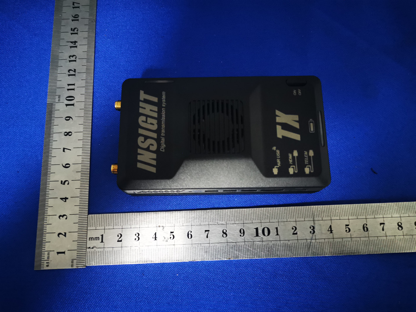
External Photos ANT
Label & label location Model: Insight Pro FCC ID: 2AK3T-INSIGHT
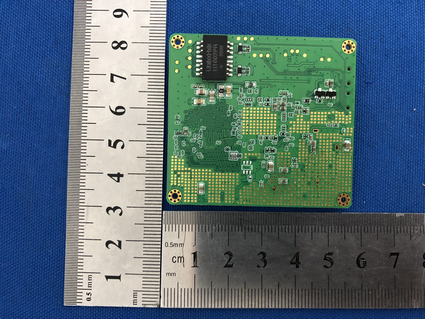
Internal Photos
FCC §15.247 (i), §2.1091 – RF Exposure FCC ID: 2AK3T-INSIGHT Applied procedures / limit According to FCC §15.247(i) and §1.1307(b)(1), systems operating under the provisions of this section shall be operated in a manner that ensures that the public is not exposed to radio frequency energy level in excess of the Commission’s guidelines. Limits for Occupational / Controlled Exposure Frequency Range (MHz) Electric Field Strength (E) (V/m) Magnetic Field Strength (H) (A/m) Power Density (S) (mW/ cm 2 ) Averaging Time |E| 2 ,|H| 2 or S (minutes) 0.3-3.0 614 1.63 (100)* 6 3.0-30 1842 / f 4.89 / f (900 / f)* 6 30-300 61.4 0.163 1.0 6 300-1500 F/300 6 1500-100,000 5 6 Note: ƒ is frequency in MHz * = Power density limit is applicable at frequencies greater than 100 MHz Limits for General Population / Uncontrolled Exposure Frequency Range (MHz) Electric Field Strength (E) (V/m) Magnetic Field Strength (H) (A/m) Power Density (S) (mW/ cm 2 ) Averaging Time |E| 2 ,|H| 2 or S (minutes) 0.3-1.34 614 1.63 (100)* 30 1.34-30 824/f 2.19/f (180/f)* 30 30-300 27.5 0.073 0.2 30 300-1500 F/1500 30 1500-100,000 1.0 30 Note: f = frequency in MHz * = Plane-wave equivalent power density MPE PREDICTION Predication of MPE limit at a given distance, Equation from OET Bulletin 65, Edition 97-01 Where: S = power density P = power input to antenna G = power gain of the antenna in the direction of interest relative to an isotropic radiator R = distance to the center of radiation of the antenna, R=0.2m TEST RESULTS Tune up Produce power Maximu m peak output power (dBm) Output power to antenn a (mW) Antenna Gain (numeric) Power Density (S) (mW/ cm2) Limit (mW / cm2 ) Result 802.11 U- NII-1 16±1 17 50.12 1.995 (3dBi) 0.0199 1 Pass 802.11 U- NII-3 16±1 17 50.12 1.995 (3dBi) 0.0199 1 Pass
Shenzhen BCTC Testing Co., Ltd. Report No.: BCTC2004001641E FCC Part 15E Test Report FCC ID: 2AK3T-INSIGHT Product Name: Insight Pro Trademark: N/A Model Name : Insight Pro Prepared For : Argus Technology (Shenzhen) Co., Ltd Address : NO.5-6A, ZhongYan Business Building, Fuyong street, FuHai Road, Baoan, Shenzhen, China. Prepared By : Shenzhen BCTC Testing Co., Ltd. Address : BCTC Building & 1-2F, East of B Building, Pengzhou Industrial, Fuyuan 1st Road, Qiaotou Community, Fuyong Street, Bao’an District, Shenzhen, China Test Date: Apr. 24, 2020 to Apr. 29, 2020 Date of Report : Apr. 29, 2020 Report No.: BCTC2004001641E Te s t Report Tel: 400-788-9558 Web: https://www.bctc-lab.com BCTC/RF-EMC-0 07 Ver.:A.0 Page 1 of 86 Shenzhen BCTC Testing Co., Ltd. Report No.: BCTC2004001641E TEST RESULT CERTIFICATION Applicant’s name ................. : Argus Technology (Shenzhen) Co., Ltd Address ................................. : NO.5-6A, ZhongYan Business Building, Fuyong street, FuHai Road, Baoan, Shenzhen, China. Manufacture's Name ............ : Argus Technology (Shenzhen) Co., Ltd Address ................................. : NO.5-6A, ZhongYan Business Building, Fuyong street, FuHai Road, Baoan, Shenzhen, China. Product description Product name ........................... : Insight Pro Trademark ................................. : N/A Model and/or type reference : Insight Pro Standards ............................. : FCC Part15 15.407 ANSI C63.10-2013 KDB 662911 D01 v02r01 KDB 789033 D02 v02r01 This device described above has been tested by BCTC, and the test results show that the equipment under test (EUT) is in compliance with the FCC requirements. And it is applicable only to the tested sample identified in the report. This report shall not be reproduced except in full, without the written approval of BCTC, this document may be altered or revised by BCTC, personal only, and shall be noted in the revision of the document. Prepared by(Engineer): Bin Mei Reviewer(Supervisor): Eric Yang Approved(Manager): Zero Zhou Te s t Report Tel: 400-788-9558 Web: https://www.bctc-lab.com BCTC/RF-EMC-0 07 Ver.:A.0 Page 2 of 86 Shenzhen BCTC Testing Co., Ltd. Report No.: BCTC2004001641E Table of Contents Page 1 . SUMMARY OF TEST RESULTS 6 1.1 TEST FACILITY 7 1.2 MEASUREMENT UNCERTAINTY 7 2 . GENERAL INFORMATION 8 2.1 GENERAL DESCRIPTION OF EUT 8 2.2 DESCRIPTION OF TEST MODES 10 2.3 BLOCK DIGRAM SHOWING THE CONFIGURATION OF SYSTEM TESTED 11 2.4 DESCRIPTION OF SUPPORT UNITS(CONDUCTED MODE) 11 2.5 EQUIPMENTS LIST FOR ALL TEST ITEMS 12 3 . EMC EMISSION TEST 14 3.1 CONDUCTED EMISSION MEASUREMENT 14 3.1.1 POWER LINE CONDUCTED EMISSION LIMITS 14 3.1.2 TEST PROCEDURE 15 3.1.3 DEVIATION FROM TEST STANDARD 15 3.1.4 TEST SETUP 15 3.1.5 EUT OPERATING CONDITIONS 15 3.1.6 TEST RESULTS 15 3.2 RADIATED EMISSION MEASUREMENT 18 3.2.1 APPLICABLE STANDARD 18 3.2.2 CONFORMANCE LIMIT 18 3.2.3 MEASURING INSTRUMENTS 18 3.2.4 TEST CONFIGURATION 19 3.2.5 TEST PROCEDURE 20 3.2.6 TEST RESULTS (9KHZ – 30 MHZ) 21 3.2.7 TEST RESULTS (30MHZ – 1GHZ) 22 3.2.8 TEST RESULTS (1GHZ-40GHZ) 24 4 . POWER SPECTRAL DENSITY TEST 30 4.1 APPLIED PROCEDURES / LIMIT 30 4.2 TEST PROCEDURE 31 4.3 DEVIATION FROM STANDARD 31 4.4 TEST SETUP 31 4.5 EUT OPERATION CONDITIONS 31 4.6 TEST RESULTS 32 5 . 26DB & 6DB & 99% EMISSION BANDWIDTH 38 5.1 APPLIED PROCEDURES / LIMIT 38 Te s t Report Tel: 400-788-9558 Web: https://www.bctc-lab.com BCTC/RF-EMC-0 07 Ver.:A.0 Page 3 of 86 Shenzhen BCTC Testing Co., Ltd. Report No.: BCTC2004001641E Table of Contents Page 5.2 TEST PROCEDURE 38 5.3 EUT OPERATION CONDITIONS 39 5.4 TEST RESULTS 40 6 . MAXIMUM CONDUCTED OUTPUT POWER 48 6.1 PPLIED PROCEDURES / LIMIT 48 6.2 TEST PROCEDURE 48 6.3 DEVIATION FROM STANDARD 50 6.4 TEST SETUP 50 6.5 EUT OPERATION CONDITIONS 50 6.6 TEST RESULTS 51 7 . OUT OF BAND EMISSIONS 53 7.1 APPLICABLE STANDARD 53 7.2 TEST PROCEDURE 53 7.3 DEVIATION FROM STANDARD 53 7.4 TEST SETUP 53 7.5 EUT OPERATION CONDITIONS 54 7.6 TEST RESULTS 55 8.SPURIOUS RF CONDUCTED EMISSIONS 66 8.1CONFORMANCE LIMIT 66 8.2MEASURING INSTRUMENTS 66 8.3TEST SETUP 66 8.4TEST PROCEDURE 66 8.5TEST RESULTS 66 9. FREQUENCY STABILITY MEASUREMENT 75 9.1 LIMIT 75 9.2 TEST PROCEDURES 75 9.3 TEST SETUP LAYOUT 75 9.4 EUT OPERATION DURING TEST 75 9.5 TEST RESULTS 76 10. ANTENNA REQUIREMENT 82 10.1 STANDARD REQUIREMENT 82 10.2 EUT ANTENNA 82 11. EUT TEST PHOTO 83 12. EUT PHOTO 85 Te s t Report Tel: 400-788-9558 Web: https://www.bctc-lab.com BCTC/RF-EMC-0 07 Ver.:A.0 Page 4 of 86 Shenzhen BCTC Testing Co., Ltd. Report No.: BCTC2004001641E Revision History Report No. Version Description Issued Date BCTC2004001641E Rev.01 Initial issue of report Apr. 29, 2020 Te s t Report Tel: 400-788-9558 Web: https://www.bctc-lab.com BCTC/RF-EMC-0 07 Ver.:A.0 Page 5 of 86 Shenzhen BCTC Testing Co., Ltd. Report No.: BCTC2004001641E 1. SUMMARY OF TEST RESULTS Test procedures according to the technical standards: FCC Part15 (15.407) , Subpart E Standard Section Test Item Judgment Remark 15.209(a), 15.407 (b)(1) 15.407 (b)(4) 15.407 (b)(6) Spurious Radiated Emissions PASS 15.207 Conducted Emission PASS 15.407 (a)(5) 15.1049 26 dB and 99% Emission Bandwidth PASS 15.407(e) Minimum 6 dB bandwidth PASS 15.407 (a)(1) 15.407 (a)(3) Maximum Conducted Output Power PASS 2.1051, 15.407(b)(1) 15.407(b)(4) Band Edge PASS 15.407 (a)(1) 15.407 (a)(3) Power Spectral Density PASS 2.1051, 15.407(b) Spurious Emissions at Antenna Terminals PASS 15.203 Antenna Requirement PASS NOTE: (1)” N/A” denotes test is not applicable in this Test Report Te s t Report Tel: 400-788-9558 Web: https://www.bctc-lab.com BCTC/RF-EMC-0 07 Ver.:A.0 Page 6 of 86 Shenzhen BCTC Testing Co., Ltd. Report No.: BCTC2004001641E 1.1 TEST FACILITY Shenzhen BCTC Testing Co., Ltd. Add. : BCTC Building & 1-2F, East of B Building, Pengzhou Industrial, Fuyuan 1st Road, Qiaotou Community, Fuyong Street, Bao’an District, Shenzhen, China FCC Te s t Firm Registration Number: 712850 IC Registered No.: 23583 1.2 MEASUREMENT UNCER…
Text truncated - open the document above for the full version.
Shenzhen BCTC Testing Co., Ltd. Report No.: BCTC2004001641E Radiated bandedge Te s t Report Tel: 400-788-9558 Web: https://www.bctc-lab.com BCTC/RF-EMC-0 07 Ver.:A.0 Page 61 of 86 Shenzhen BCTC Testing Co., Ltd. Report No.: BCTC2004001641E Note: 1. This EUT was tested in 802.11a/n(HT20), n(HT40) mode and 802.11a Antenna A the worst case position data was reported. Te s t Report Tel: 400-788-9558 Web: https://www.bctc-lab.com BCTC/RF-EMC-0 07 Ver.:A.0 Page 62 of 86 Shenzhen BCTC Testing Co., Ltd. Report No.: BCTC2004001641E 802.11n(HT20) For the frequency band 5745-5825MHz Low Channel Te s t Report Tel: 400-788-9558 Web: https://www.bctc-lab.com BCTC/RF-EMC-0 07 Ver.:A.0 Page 63 of 86 Shenzhen BCTC Testing Co., Ltd. Report No.: BCTC2004001641E Middle Channel Te s t Report Tel: 400-788-9558 Web: https://www.bctc-lab.com BCTC/RF-EMC-0 07 Ver.:A.0 Page 64 of 86 Shenzhen BCTC Testing Co., Ltd. Report No.: BCTC2004001641E High Channel Note: 1. This EUT was tested in 802.11a/n/ac(HT20), n/ac(HT40), ac(HT80) mode and 802.11n(HT20) Antenna A the worst case position data was reported. Te s t Report Tel: 400-788-9558 Web: https://www.bctc-lab.com BCTC/RF-EMC-0 07 Ver.:A.0 Page 65 of 86 Shenzhen BCTC Testing Co., Ltd. Report No.: BCTC2004001641E 8.SPURIOUS RF CONDUCTED EMISSIONS 8.1CONFORMANCE LIMIT Undesirable emission limits. Except as shown in paragraph (b)(7) of this section, the maximum emissions outside of the frequency bands of operation shall be attenuated in accordance with the following limits: (1) For transmitters operating in the 5.15-5.25 GHz band: All emissions outside of the 5.15-5.35 GHz band shall not exceed an e.i.r.p. of −27 dBm/MHz. (2) For transmitters operating in the 5.725-5.85 GHz band(i) All emissions shall be limited to a level of −27 dBm/MHz at 75 MHz or more above or below the band edge increasing linearly to 10 dBm/MHz at 25 MHz above or below the band edge, and from 25 MHz above or below the band edge increasing linearly to a level of 15.6 dBm/MHz at 5 MHz above or below the band edge, and from 5 MHz above or below the band edge increasing linearly to a level of 27 dBm/MHz at the band edge. . 8.2MEASURING INSTRUMENTS The Measuring equipment is listed in the section 6.3 of this test report. 8.3TEST SETUP Please refer to Section 6.1 of this test report. 8.4TEST PROCEDURE 1. Check the calibration of the measuring instrument using either an internal calibrator or a known signal from an external generator. 2. Position the EUT without connection to measurement instrument. Turn on the EUT and connect its antenna terminal to measurement instrument via a low loss cable. Then set it to any one measured frequency within its operating range, and make sure the instrument is operated in its linear range. 3. Set RBW of spectrum analyzer to 1 MHz with a convenient frequency span. 4. Measure the highest amplitude appearing on spectral display and set it as a reference level. Plot the graph with marking the highest point and edge frequency. 5. Repeat above procedures until all measured frequencies were complete . 8.5TEST RESULTS Remark: The measurement frequency range is from 9KHz to the 10th harmonic of the fundamental frequency. The lowest, middle and highest channels are tested to verify the spurious emissions and bandege measurement data. About:26.5GHz-40GHz, The amplitude of spurious emissions which are attenuated by more than 20dB below the permissible value has no need to be reported. Note: A(B) Represent the value of antenna A and B, The worst data is Antenna A ,only shown Antenna A Plot. Te s t Report Tel: 400-788-9558 Web: https://www.bctc-lab.com BCTC/RF-EMC-0 07 Ver.:A.0 Page 66 of 86 Shenzhen BCTC Testing Co., Ltd. Report No.: BCTC2004001641E 5.1G 802.11a on channel 36 802.11a on channel 40 802.11a on channel 36 802.11a on channel 40 802.11a on channel 36 802.11a on channel 40 Te s t Report Tel: 400-788-9558 Web: https://www.bctc-lab.com BCTC/RF-EMC-0 07 Ver.:A.0 Page 67 of 86 Shenzhen BCTC Testing Co., Ltd. Report No.: BCTC2004001641E Test Plot 802.11a on channel 48 802.11n20 on channel 36 802.11a on channel 48 802.11n20 on channel 36 802.11a on channel 48 802.11n20 on channel 36 Te s t Report Tel: 400-788-9558 Web: https://www.bctc-lab.com BCTC/RF-EMC-0 07 Ver.:A.0 Page 68 of 86 Shenzhen BCTC Testing Co., Ltd. Report No.: BCTC2004001641E Test Plot 802.11n20 on channel 40 802.11n20 on channel 48 802.11n20 on channel 40 802.11n20 on channel 48 802.11n20 on channel 40 802.11n20 on channel 48 Te s t Report Tel: 400-788-9558 Web: https://www.bctc-lab.com BCTC/RF-EMC-0 07 Ver.:A.0 Page 69 of 86 Shenzhen BCTC Testing Co., Ltd. Report No.: BCTC2004001641E Test Plot 802.11n40 on channel 38 802.11n40 on channel 46 802.11n40 on channel 38 802.11n40 on channel 46 802.11n40 on channel 38 802.11n40 on channel 46 Te s t Report Tel: 400-788-9558 Web: https://www.bctc-lab.com BCTC/RF-EMC-0 07 Ver.:A.0 Page 70 of 86 Shenzhen BCTC Testing Co., Ltd. Report No.: BCTC2004001641E 5.8G Test Plot 802.11a on channel 149 802.11a on channel 157 802.11a on channel 149 802.11a on channel 157 802.11a on channel 149 802.11a on channel 157 Te s t Report Tel: 400-788-9558 Web: https://www.bctc-lab.com BCTC/RF-EMC-0 07 Ver.:A.0 Page 71 of 86 Shenzhen BCTC Testing Co., Ltd. Report No.: BCTC2004001641E Test Plot 802.11a on channel 165 802.11n20 on channel 149 802.11a on channel 165 802.11n20 on channel 149 802.11a on channel 165 802.11n20 on channel 149 Te s t Report Tel: 400-788-9558 Web: https://www.bctc-lab.com BCTC/RF-EMC-0 07 Ver.:A.0 Page 72 of 86 Shenzhen BCTC Testing Co., Ltd. Report No.: BCTC2004001641E Test Plot 802.11n20 on channel 157 802.11n20 on channel 165 802.11n20 on channel 157 802.11n20 on channel 165 802.11n20 on channel 157 802.11n20 on channel 165 Te s t Report Tel: 400-788-9558 Web: https://www.bctc-lab.com BCTC/RF-EMC-0 07 Ver.:A.0 Page 73 of 86 Shenzhen BCTC Testing Co., Ltd. Report No.: BCTC2004001641E Test Plot 802.11n40 on channel 151 802.11n40 on channel 159 802.11n40 on channel 1…
Text truncated - open the document above for the full version.
Conducted Measurement Photos Radiated Measurement Photos
| # | Rule Parts | Frequency Range | Power Output |
|---|---|---|---|
| 2 | 15E | 5.75 GHz - 5.83 GHz | 44.26 mW |

Insight mini
Equipment Class
NII - Unlicensed National Information Infrastructure TX