2AK53ML2LAUMSVLED Ceiling light
Dong Guan Bright Yin Huey Lighting Co., Ltd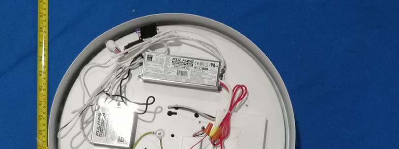
Click to zoom
Application Details
- Equipment Class
- DXX - Part 15 Low Power Communication Device Transmitter
- Date of Grant
- Jun 23, 2020
- Application Purpose
- Original Equipment
- Date of Application
- Jun 23, 2020
- Equipment Note
- LED Ceiling light
- Frequency Range
- 5801.00000000 - 5801.00000000
- Country
- China
Documents & Files
Document Text
Text extracted from the exhibit documents filed with the FCC. Open a document above to read the original.
Users Manual
Operating Instructions MaxLite ® LED Architectural Brushed Nickel Ceiling Fixture © Copyright 2017. MaxLite, Inc. All Rights Reserved. 12 York Ave, West Caldwell, NJ 07006 Tel: 973-244-7300 Fax: 973-244-7333 Email: [email protected] Page: 1 REV: 10/12/17 General Safety Information • To reduce the risk of death, personal injury or property damage from fire, electric shock, falling parts, cuts/abrasions, and other hazards read all warnings and instructions included with and on the fixture box and all fixture labels. • Before installing, servicing, or performing routine maintenance upon this equipment, follow these general precautions. • Commercial installation, service and maintenance of luminaires should be performed by a qualified licensed electrician. • For Residential installation: If you are unsure about the installation or maintenance of the luminaires, consult a qualified licensed electrician and check your local electrical code. • DO NOT INSTALL DAMAGED PRODUCT! • This fixture is intended to be connected to a properly installed and grounded UL listed junction box. WARNING: Picture is for illustration purposes only. Your model may vary. Operating Instructions MaxLite ® LED Architectural Brushed Nickel Ceiling Fixture © Copyright 2017. MaxLite, Inc. All Rights Reserved. 12 York Ave, West Caldwell, NJ 07006 Tel: 973-244-7300 Fax: 973-244-7333 Email: [email protected] Page: 2 REV: 10/12/17 • Risk of Fire - Supply conductors (power wires) connecting the fixture must be rated minimum 90 . If uncertain consult an electrician. • Risk of Fire/Electric Shock - If not qualified, do not attempt installation. Contact a qualified electrician. CAUTION: • For your safety read and understand instructions completely before starting installation. • To prevent wiring damage or abrasion, do not expose wiring to edges of sheet metal or other sharp objects. • Before attempting installation, check your local electrical code, as it sets the wiring standards for your locality. NOTES: • If luminaire (fixture) is to be switched from a wall switch, make sure black power supply wire is connected to the switch. DO NOT connect the white supply wire to the switch. • Make certain no bare wires are exposed outside the wire nut connectors. • Do not make or alter any open holes in an enclosure of wiring or electrical components during kit installation. • Warranty is not applicable to lamps not installed in compliance with: - National Electrical Code (NEC) - The Standard for Safety of Underwriters Laboratories Inc. (UL) Models: ML2LASABNU169CSMSV ,ML2LAMABNU209CSMSV, ML2LALABNU249CSMSV, ML2LASABNU169CSEMMSV, ML2LAMABNU209CSEMMSV, ML2LALABNU249CSEMMSV ML2LASPWHU169CSMSV,ML2LAMPWHU209CSMSV,ML2LALPWHU249CSMS,ML2LASPWHU169CSEMMSV,ML2LAMP WHU209CSEMMSV, ML2LALPWHU249CSEMMSV Input Rating: 120-277VAC 50/60Hz Operating Temperature: -20C° to 40°C Damp Location Rated Package Contents: 1 - Round Flushmount Housing 3 - Wirenuts (in parts bag) 1 - Round Flushmount Diffuser (shipped as part of flushmount housing) 2 - 1 ½” Electrical Box Screws (in parts bag) 1 - Installation Manual Any Changes expressly or modifications not approved by the party responsible for compliance could void the user's authority to operate the equipment. This device complies with part 15 of the FCC Rules. Operation is subject to the following two conditions: (1) This device may not cause harmful interference, and (2) this device must accept any interference received, including interference that may cause undesired operation. Note: This equipment has been tested and found to comply with the limits for a Class B digital device, pursuant to part 15 of the FCC Rules. These limits are designed to provide reasonable protection against harmful interference in a residential installation. This equipment generates, uses and can radiate radio frequency energy and, if not installed and used in accordance with the instructions, may cause harmful interference to radio communications. However, there is no guarantee that interference will not occur in a particular installation. If this equipment does cause harmful interference to radio or television reception, which can be determined by turning the equipment off and on, the user is encouraged to try to correct the interference by one or more of the following measures: —Reorient or relocate the receiving antenna. —Increase the separation between the equipment and receiver. —Connect the equipment into an outlet on a circuit different from that to which the receiver is connected. —Consult the dealer or an experienced radio/TV technician for help. FCC Radiation Exposure Statement: This equipment complies with FCC radiation exposure limits set forth for an uncontrolled environment . This transmitter must not be co‐located or operating in conjunction with any other antenna or transmitter. Operating Instructions MaxLite ® LED Architectural Brushed Nickel Ceiling Fixture © Copyright 2017. MaxLite, Inc. All Rights Reserved. 12 York Ave, West Caldwell, NJ 07006 Tel: 973-244-7300 Fax: 973-244-7333 Email: [email protected] Page: 3 REV: 10/12/17 General Wiring Diagram CAUTION: Turn off electrical power at fuse or circuit breaker box before wiring fixture to the power supply. Luminaires Operating Instructions MaxLite ® LED Architectural Brushed Nickel Ceiling Fixture © Copyright 2017. MaxLite, Inc. All Rights Reserved. 12 York Ave, West Caldwell, NJ 07006 Tel: 973-244-7300 Fax: 973-244-7333 Email: [email protected] Page: 4 REV: 10/12/17 Installation Instructions WARNING: RISK OF ELECTRICAL SHOCK • Turn off electrical power at fuse or circuit breaker box before wiring fixture to the power supply. • Turn off the power when you perform any maintenance. • Verify that supply voltage is correct by comparing it with the luminaire label information. • Make all electrical and grounded connections in accordance with the National Electrical Code and any applicable local code requirements. • All wiring connections should be capped with UL approved wire …
Text truncated - open the document above for the full version.
External Photos
EXHIBIT B - EUT EXTERNAL PHOTOGRAPHS Model: ML2LALABNU249CSMSV Model: ML2LAMPWHU209CSMSV
ID Label/Location Info
This device complies with Part 15 of the FCC Rules.Operation is subject to the following two conditions: (1) This device may not cause harmful interference, and (2) this device must accept any interference received, including interference that may cause undesired operation. Este dispositivo cumple con la Parte 15 de las Reglas de la FCC.La operación está sujeta a las dos siguientes condiciones: (1) Este dispositivo no provoca ninguna Interferencia perjudicial, (2) Este dispositivo aceptará cualquier interferencia que reciba, incluyendo aquellas que provoquen una operación no deseada. FCC ID:2AK53ML2LAUMSV 4003504 MODEL/MODÈLE:ML2LASABNU169CSEMMSV 120-277V AC 50/60Hz 16W CONFORMS TO UL STD. 1598 CONFORME À LA NORME UL1598 CERTIFIED TO CSA STD. C22.2 No. 250.0 CERTIFIÉ SELON LA NORME CSA C22.2 No. 250.0 MADE IN CHINA/FABRIQUÉ EN CHINE 20F256101 KLD3001LS-EM-MSV 2700K 3000K 3500K 4000K 5000K MIN 90 °C SUPPLY CONDUCTORS LES FILS D’ALIMENTATION 90 °C MIN SUITABLE FOR DAMP LOCATIONS CONVIENT AUX EMPLACEMENTS HUMIDES MAXIMUM AMBIENT OPERATING TEMPERATURE 40°C TEMPÉRATURE AMBIANTE MAXIMALE DE FONCTIONNEMENT 40°C CAUTION – RISK OF FIRE / ATTENTION – RISQUE D’INCENDIE CAN ICES-005(B)/NMB-005(B) CLASS 1 WIRING ONLY CLASSE 1 CÂBLAGE SEULEMENT JA8-2019 This device complies with Part 15 of the FCC Rules.Operation is subject to the following two conditions: (1) This device may not cause harmful interference, and (2) this device must accept any interference received, including interference that may cause undesired operation. Este dispositivo cumple con la Parte 15 de las Reglas de la FCC.La operación está sujeta a las dos siguientes condiciones: (1) Este dispositivo no provoca ninguna Interferencia perjudicial, (2) Este dispositivo aceptará cualquier interferencia que reciba, incluyendo aquellas que provoquen una operación no deseada. FCC ID:2AK53ML2LAUMSV 4003504 MODEL/MODÈLE:ML2LAMABNU209CSEMMSV 120-277V AC 50/60Hz 20W CONFORMS TO UL STD. 1598 CONFORME À LA NORME UL1598 CERTIFIED TO CSA STD. C22.2 No. 250.0 CERTIFIÉ SELON LA NORME CSA C22.2 No. 250.0 MADE IN CHINA/FABRIQUÉ EN CHINE 20F256101 CLASS 1 WIRING ONLY KLD3001L-EM-MSV CLASSE 1 CÂBLAGE SEULEMENT MIN 90 °C SUPPLY CONDUCTORS LES FILS D’ALIMENTATION 90 °C MIN SUITABLE FOR DAMP LOCATIONS CONVIENT AUX EMPLACEMENTS HUMIDES MAXIMUM AMBIENT OPERATING TEMPERATURE 40°C TEMPÉRATURE AMBIANTE MAXIMALE DE FONCTIONNEMENT 40°C CAUTION – RISK OF FIRE / ATTENTION – RISQUE D’INCENDIE CAN ICES-005(B)/NMB-005(B) 2700K 3000K 3500K 4000K 5000K JA8-2019 This device complies with Part 15 of the FCC Rules.Operation is subject to the following two conditions: (1) This device may not cause harmful interference, and (2) this device must accept any interference received, including interference that may cause undesired operation. Este dispositivo cumple con la Parte 15 de las Reglas de la FCC.La operación está sujeta a las dos siguientes condiciones: (1) Este dispositivo no provoca ninguna Interferencia perjudicial, (2) Este dispositivo aceptará cualquier interferencia que reciba, incluyendo aquellas que provoquen una operación no deseada. FCC ID:2AK53ML2LAUMSV 4003504 MODEL/MODÈLE:ML2LALABNU249CSEMMSV 120-277V AC 50/60Hz 24W CONFORMS TO UL STD. 1598 CONFORME À LA NORME UL1598 CERTIFIED TO CSA STD. C22.2 No. 250.0 CERTIFIÉ SELON LA NORME CSA C22.2 No. 250.0 MADE IN CHINA/FABRIQUÉ EN CHINE 20F256101 KLD3001LL-EM-MSV MIN 90 °C SUPPLY CONDUCTORS LES FILS D’ALIMENTATION 90 °C MIN SUITABLE FOR DAMP LOCATIONS CONVIENT AUX EMPLACEMENTS HUMIDES MAXIMUM AMBIENT OPERATING TEMPERATURE 40°C TEMPÉRATURE AMBIANTE MAXIMALE DE FONCTIONNEMENT 40°C CAUTION – RISK OF FIRE / ATTENTION – RISQUE D’INCENDIE CAN ICES-005(B)/NMB-005(B) CLASS 1 WIRING ONLY CLASSE 1 CÂBLAGE SEULEMENT 2700K 3000K 3500K 4000K 5000K JA8-2019
Internal Photos
EXHIBIT C - EUT INTERNAL PHOTOGRAPHS Model: ML2LALABNU249CSMSV Antenna Model: ML2LAMPWHU209CSMSV Antenna
Test Report
FCC PART 15.249 TEST REPORT For Dong Guan Bright Yin Huey Lighting Co., Ltd Dong Guan Township,Humen Town,DaNing Manage District,Da Pan Di Industrial Zone,Dongguan,China. FCC ID: 2AK53ML2LAUMSV Report Type: Original Report Product Type: LED Ceiling light Re port Number: RDG200402050-00A Re port Date: 2020-06-01 Reviewed By: Ivan Cao Assistant Manager Test Laboratory: Bay Area Compliance Laboratories Corp. (Dongguan) No.69 Pulongcun, Puxinhu Industry Area, Tangxia, Dongguan, Guangdong, China Tel: +86-769-86858888 Fax: +86-769-86858891 www.baclcorp.com.cn Bay Area Compliance Laboratories Corp. (Dongguan) Report No.: RDG200402050-00A Page 2 of 28 TABLE OF CONTENTS GENERAL INFORMATION ....................................................................................................................................... 3 PRODUCT DESCRIPTION FOR EQUIPMENT UNDER TEST (EUT) ..................................................................................... 3 OBJECTIVE ................................................................................................................................................................... 3 RELATED SUBMITTAL(S)/GRANT(S) ............................................................................................................................. 3 TEST METHODOLOGY .................................................................................................................................................. 3 MEASUREMENT UNCERTAINTY .................................................................................................................................... 4 TEST FACILITY ............................................................................................................................................................. 4 DECLARATIONS ............................................................................................................................................................ 4 SYSTEM TEST CONFIGURATION .......................................................................................................................... 5 JUSTIFICATION ............................................................................................................................................................. 5 EUT EXERCISE SOFTWARE .......................................................................................................................................... 5 EQUIPMENT MODIFICATIONS ....................................................................................................................................... 5 BLOCK DIAGRAM OF TEST SETUP ................................................................................................................................ 5 SUMMARY OF TEST RESULTS ............................................................................................................................... 6 FCC§15.203 - ANTENNA REQUIREMENT .............................................................................................................. 7 APPLICABLE STANDARD .............................................................................................................................................. 7 ANTENNA CONNECTOR CONSTRUCTION ...................................................................................................................... 7 FCC §15.207 (A)– AC LINE CONDUCTED EMISSIONS ....................................................................................... 8 APPLICABLE STANDARD .............................................................................................................................................. 8 EUT SETUP .................................................................................................................................................................. 8 EMI TEST RECEIVER SETUP ......................................................................................................................................... 8 TEST PROCEDURE ........................................................................................................................................................ 9 CORRECTED AMPLITUDE & MARGIN CALCULATION ................................................................................................... 9 TEST EQUIPMENT LIST AND DETAILS ........................................................................................................................... 9 TEST DATA ................................................................................................................................................................ 10 FCC§15.205, §15.209&§15.249- RADIATED EMISSIONS .................................................................................... 14 APPLICABLE STANDARD ............................................................................................................................................ 14 EUT SETUP ................................................................................................................................................................ 14 TEST EQUIPMENT SETUP ............................................................................................................................................ 15 TEST PROCEDURE ...................................................................................................................................................... 16 CORRECTED AMPLITUDE & MARGIN CALCULATION ................................................................................................. 16 TEST EQUIPMENT LIST AND DETAILS ......................................................................................................................... 17 TEST DATA ................................................................................................................................................................ 17 FCC §15.215(C) – 20 DB BANDWIDTH TEST…
Text truncated - open the document above for the full version.
Test Setup Photos
EXHIBIT D - TEST SETUP PHOTOGRAPHS Conducted Emissions Front View Conducted Emissions Side View Radiated Emission Below 1GHz Radiated Emission Above 1GHz
Contact Information
Applicant
Wu Bin
Test Firm
Bay Area Compliance Laboratories Corp.(Dongguan)David Zhang
[email protected]0086 0769 86858888
Technical Specifications
| # | Rule Parts | Frequency Range | Power Output |
|---|---|---|---|
| 2 | 15C | 5.80 GHz - 5.80 GHz | - |