2AKC6XHT-6B14WIRELESS USB ADAPTER
SHEN ZHEN XIN HUA TIAN TECHNOLOGY CO., LTD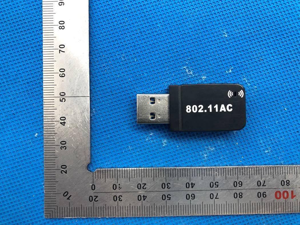
Click to zoom
Application Details
- Equipment Class
- NII - Unlicensed National Information Infrastructure TX
- Date of Grant
- May 12, 2020
- Application Purpose
- Original Equipment
- Date of Application
- May 12, 2020
- Equipment Note
- WIRELESS USB ADAPTER
- Frequency Range
- 5180.00000000 - 5240.00000000
- Country
- China
Documents & Files
Document Text
Text extracted from the exhibit documents filed with the FCC. Open a document above to read the original.
Users Manual
Dual Band Wireless USB Adapter User Manual 1. Introduction Thank you for purchasing the wireless 802.11b/g/n/a/ac USB adapter! This adapter is mini size design and you are able to plug it into the USB port. Excepting common wireless standards 802.11b/g/n, this wireless adapter is also 802.11ac compatible - data transfer rate is 150/433Mbps, and that’s three times faster than 802.11g wireless network! System Support: Windows XP/Vista/Win7/8/10/Mac 2: Quick Installation Guide 1. Insert CD into your computer’s CD drive, double click “D” Drive OR you can open the “D” drive. 2. Select proper file for your system “Windows/Mac/Linux” 3. Select your system “Win/Mac/Linux”,follow the direction to finish the installation 4. 2.Double left-click on the setup.exe file and follow the direction to finish the installation. 5.Once the installation is finished the computer will be asked to reboot. you can click ‘Finish’ and reboot the computer to finish the installation of driver files. 6.A new icon will appear near the clock of system tray: Connect to the Internet: 7.Wireless utility will appear. Click ‘Available Network’ menu to search for wireless access points nearby. 8.Choose your network and enter the password 9.Connection successful(if you entered the password,but network don’t work,pls try to return your Router) 3.AP mode for Win8.1/8/7/vista/xp/2000 Right-click Client configuration utility icon, and click Open Config Utility Select Mode and then select Access Point. It requires few seconds to switch to AP mode, please be patient Client mode icon AP mode icon Configure SSID and Channel Please note that Ad-Hoc mode is not available when network card is in AP mode 4.Quick Installation Guide for MAC o FCC statement This device complies with Part 15 of the FCC Rules: Operation is subject to the following two conditions: 1. This device may not cause harmful interference and 2. This device must accept any interference that is received, including any interfer ence that may cause undesired operation. *RF warning for Portable device: The device has been evaluated to meet general RF exposure requirement. The device can be used in portable exposure condition without restriction. This device is acting as master and operating in the 2.4 GHz (2412 ~2462 MHz) band. NOTE: This equipment has been tested and found to comply with the limits for a Class B digital device, pursuant to part 15 of the FCC Rules. These limits are designed to provide reasonable protection against harmful interference in a residential installation. This equipment generates uses and can radiate radio frequency energy and, if not installed and used in accordance with the instructions, may cause harmful interference to radio communications. However, there is no guarantee that interference will not occur in a particular installation. If this equipment does cause harmful interference to radio or television reception, which can be determined by turning the equipment off and on, the user is encouraged to try to correct the interference by one or more of the following measures: - Reorient or relocate the receiving antenna. - Increase the separation between the equipment and receiver. -Connect the equipment into an outlet on a circuit different from that to which the receiver is connected. -Consult the dealer or an experienced radio/TV technician for help
External Photos
External Photos TOP VIEW OF EUT BOTTOM VIEW OF EUT FRONT VIEW OF EUT BACK VIEW OF EUT LEFT VIEW OF EUT RIGHT VIEW OF EUT TOP VIEW OF EUT-6B15 TOP VIEW OF EUT-6B13
ID Label/Location Info
FCC ID Label Location FCC ID: 2AKC6XHT-6B14
Internal Photos
Internal Photos OPEN VIEW OF EUT INTERNAL VIEW-1 OF EUT Antenna 1 Antenna 2 INTERNAL VIEW-2 OF EUT INTERNAL VIEW-3 OF EUT INTERNAL VIEW-4 OF EUT
Operational Description
SHEN ZHEN XIN HUA TIAN TECHNOLOGY CO., LTD 3Foor, B Buliding, DaHong Industrial Park, GuangMin District, Shenzhen City, China Declaration concerning Antenna Specification It is hereby declared that the product Model No.: 6B14, 6B13, 6B15 FCC ID: 2AKC6XHT-6B14 fulfills the requirement in FCC test relating to the antenna type. The device specified above confirms to the FCC recommendations for internal antenna type(s) described below: 1 Type of antenna: Integral Antenna Gain of the antenna: 5 dBi Frequency range: 2402-2480 MHz, 5150 MHz~5250MHz 2 Type of antenna: Integral Antenna Gain of the antenna: 5 dBi Frequency range: 2402-2480 MHz, 5150 MHz~5250MHz The mounting of the antenna is fixed to the radio module and no other antenna should be used. Company name: SHEN ZHEN XIN HUA TIAN TECHNOLOGY CO., LTD Address: 3Foor, B Buliding, DaHong Industrial Park, GuangMin District, Shenzhen City, China Place: Shenzhen Date: 2020-05-11 Signature:
RF Exposure Info
RF EXPOSURE EVALUATION 1. PRODUCT INFORMATION Product Description WIRELESS USB ADAPTER Model Name 6B14, 6B13, 6B15 FCC ID 2AKC6XHT-6B14 2. EVALUATION METHOD According to 447498 D01 General RF Exposure Guidance v05 The 1-g and 10-g SAR test exclusion thresholds for 100 MHz to 6 GHz at test separation distances ≤ 50 mm are determined by: [(max. power of channel, including tune-up tolerance, mW)/(min. test separation distance, mm)] ·[√f(GHz)] ≤ 3.0 for 1-g SAR and ≤ 7.5 for 10-g extremity SAR. Where f(GHz) is the RF channel transmit frequency in GHz Power and distance are rounded to the nearest mW and mm before calculation 3. CALCULATION According to the follow transmitter output power(P t )formula: P t =(E x d) 2 /(30 x g t ) P t =transmitter output power in watts g t =numeric gain of the transmitting antenna (unitess) E=electric field strength in V/m d=measurement distance in meters (m) For 2.4G WIFI P t =8.02dBm=6.34mW The result for RF exposure evaluation SAR=(6.34mW /5mm) .[√2.462(GHz)]= 1.99<3.0 for 1-g SAR For 5G WIFI P t =7.64dBm=5.81mW The result for RF exposure evaluation SAR=(5.81mW /5mm) .[√5.24(GHz)]=2.66<3.0 for 1-g SAR Note: The 2.4G and 5G WIFI can not transmit simultaneously. 4. CONCLUSION The SAR evaluation is not required.
Test Report
Page 1 of 82 Report No.: AGC00742200402FE06 FCC ID : 2AKC6XHT-6B14 APPLICATION PURPOSE : Original Equipment PRODUCT DESIGNATION : WIRELESS USB ADAPTER BRAND NAME : N/A MODEL NAME : 6B14, 6B13, 6B15 APPLICANT : SHEN ZHEN XIN HUA TIAN TECHNOLOGY CO., LTD. DATE OF ISSUE : Apr. 28, 2020 STANDARD(S) TEST PROCEDURE(S) : FCC Part 15.407 KDB 789033 D02 v02r01 REPORT VERSION : V1.0 Attestation of Global Compliance (Shenzhen) Co., Ltd CAUTION: This report shall not be reproduced except in full without the written permission of the test laboratory and shall not be quoted out of context. FCC Test Report Report No.: AGC00742200402FE06 Page 2 of 82 REPORT REVISE RECORD Report Version Revise Time Issued Date Valid Version Notes V1.0 / Apr. 28, 2020 Valid Initial Release Report No.: AGC00742200402FE06 Page 3 of 82 TABLE OF CONTENTS 1. VERIFICATION OF CONFORMITY ............................................................................................................... 5 2. GENERAL INFORMATION ............................................................................................................................ 6 2.1. PRODUCT DESCRIPTION ..................................................................................................................... 6 2.2. TABLE OF CARRIER FREQUENCYS ..................................................................................................... 6 2.3. RELATED SUBMITTAL(S) / GRANT (S) .................................................................................................. 7 2.4. TEST METHODOLOGY .......................................................................................................................... 7 2.5. SPECIAL ACCESSORIES ....................................................................................................................... 7 2.6. EQUIPMENT MODIFICATIONS .............................................................................................................. 7 3. MEASUREMENT UNCERTAINTY ................................................................................................................. 8 4. DESCRIPTION OF TEST MODES ................................................................................................................. 9 5. SYSTEM TEST CONFIGURATION ............................................................................................................. 10 5.1. CONFIGURATION OF EUT SYSTEM ................................................................................................... 10 5.2. EQUIPMENT USED IN EUT SYSTEM ................................................................................................... 10 5.3. SUMMARY OF TEST RESULTS ............................................................................................................ 10 6. TEST FACILITY ........................................................................................................................................... 11 7. MAXIMUM CONDUCTED OUTPUT POWER .............................................................................................. 12 7.1. MEASUREMENT PROCEDURE ........................................................................................................... 12 7.2. TEST SET-UP ........................................................................................................................................ 12 7.3. LIMITS AND MEASUREMENT RESULT ............................................................................................... 13 8. EMISSION BANDWIDTH ............................................................................................................................. 15 8.1. MEASUREMENT PROCEDURE ........................................................................................................... 15 8.2. TEST SET-UP (BLOCK DIAGRAM OF CONFIGURATION) ................................................................... 15 8.3. LIMITS AND MEASUREMENT RESULTS ............................................................................................. 16 9. MAXIMUM CONDUCTED OUTPUT PEAK POWER SPECTRAL DENSITY .............................................. 24 9.1 MEASUREMENT PROCEDURE ............................................................................................................ 24 9.2 TEST SET-UP (BLOCK DIAGRAM OF CONFIGURATION) .................................................................... 24 9.3 MEASUREMENT EQUIPMENT USED ................................................................................................... 24 9.4 LIMITS AND MEASUREMENT RESULT ................................................................................................ 24 10. CONDUCTED SPURIOUS EMISSION ...................................................................................................... 40 10.1. MEASUREMENT PROCEDURE ......................................................................................................... 40 Report No.: AGC00742200402FE06 Page 4 of 82 10.2. TEST SET-UP (BLOCK DIAGRAM OF CONFIGURATION) ................................................................. 40 10.3. MEASUREMENT EQUIPMENT USED ................................................................................................ 40 10.4. LIMITS AND MEASUREMENT RESULT ............................................................................................. 40 11. RADIATED EMISSION ............................................................................................................................... 52 11.1. MEASUREMENT PROCEDURE ......................................................................................................... 52 11.2. TEST SETUP ....................................................................................................................................... 53 11.3. LIMITS AND MEASUREMENT RESULT .............................................................................................…
Text truncated - open the document above for the full version.
Test Report
Report No.: AGC00742200402FE06 Page 56 of 82 EUT WIRELESS USB ADAPTER Model Name 6B14 Temperature 25°C Relative Humidity 55.4% Pressure 960hPa Test Voltage Normal Voltage Test Mode 802.11a20 5180MHz Antenna Vertical RESULT: PASS Note: All test channels had been tested. The 802.11a20 at 5180MHz is the worst case and recorded in the test report. Factor = Antenna Factor + Cable loss - Amplifier gain, Margin= Limit-Level. The “Factor” value can be calculated automatically by software of measurement system. Report No.: AGC00742200402FE06 Page 57 of 82 RADIATED EMISSION ABOVE 1GHZ EUT WIRELESS USB ADAPTER Model Name 6B14 Temperature 25°C Relative Humidity 55.4% Pressure 960hPa Test Voltage Normal Voltage Test Mode 802.11a20 5180MHz Antenna Horizontal/Vertical RADIATED EMISSION ABOVE 1GHZ–Horizontal FrequencyMeter ReadingFactor Emission LevelLimitsMargin (MHz)(dBμV) (dB)(dBμV/m)(dBμV/m)(dB) Value Type 10360.042peak 10360.042AVG 15540.063peak 15540.063AVG 46.26 9.1455.40 74.00 -18.60 36.34 9.1445.48 54.00 -8.52 44.78 10.2255.00 74.00 -19.00 35.13 10.2245.35 54.00 -8.65 Remark: Factor = Antenna Factor + Cable Loss – Pre-amplifier. RADIATED EMISSION ABOVE 1GHZ–Vertical FrequencyMeter ReadingFactor Emission LevelLimitsMargin (MHz)(dBμV) (dB)(dBμV/m)(dBμV/m)(dB) Value Type 10360.042peak 10360.042AVG 15540.063peak 15540.063AVG 45.23 9.1454.37 74.00 -19.63 36.15 9.1445.29 54.00 -8.71 43.99 10.2254.21 74.00 -19.79 35.09 10.2245.31 54.00 -8.69 Remark: Factor = Antenna Factor + Cable Loss – Pre-amplifier. Report No.: AGC00742200402FE06 Page 58 of 82 EUT WIRELESS USB ADAPTER Model Name 6B14 Temperature 25°C Relative Humidity 55.4% Pressure 960hPa Test Voltage Normal Voltage Test Mode 802.11a20 5240MHz Antenna Horizontal/Vertical RADIATED EMISSION ABOVE 1GHZ–Horizontal FrequencyMeter ReadingFactor Emission LevelLimitsMargin (MHz)(dBμV) (dB)(dBμV/m)(dBμV/m)(dB) Value Type 10480.042peak 10480.042AVG 15720.063peak 15720.063AVG 46.39 9.2755.66 74.00 -18.34 37.12 9.2746.39 54.00 -7.61 43.33 10.3853.71 74.00 -20.29 34.25 10.3844.63 54.00 -9.37 Remark: Factor = Antenna Factor + Cable Loss – Pre-amplifier. RADIATED EMISSION ABOVE 1GHZ–Vertical FrequencyMeter ReadingFactor Emission LevelLimitsMargin (MHz)(dBμV) (dB)(dBμV/m)(dBμV/m)(dB) Value Type 10480.042peak 10480.042AVG 15720.063peak 15720.063AVG 45.16 9.2754.43 74.00 -19.57 36.29 9.2745.56 54.00 -8.44 43.87 10.3854.25 74.00 -19.75 34.15 10.3844.53 54.00 -9.47 Remark: Factor = Antenna Factor + Cable Loss – Pre-amplifier. Note: All the case had been tested. The 802.11a modulation is the worst case and recorded in the test report. Other frequencies radiation emission from 1GHz to 40GHz at least have 20dB margin and not recorded in the test report. Factor = Antenna Factor + Cable loss - Amplifier gain, Margin= Limit-Level. The “Factor” value can be calculated automatically by software of measurement system. Report No.: AGC00742200402FE06 Page 59 of 82 12. BAND EDGE EMISSION 12.1. MEASUREMENT PROCEDURE 1. The EUT operates at transmitting mode. The operate channel is tested to verify the largest transmission and spurious emissions power at the continuous transmission mode. 2. Set the spectrum analyzer in the following setting in order to capture the lower and upper band-edges of the emission: (a) PEAK: RBW=1MHz, VBW=3MHz / Sweep=AUTO (b) AVERAGE: RBW=1MHz ; VBW=1/on time(1KHz) / Sweep=AUTO 3. Other procedures refer to clause 11.2. Note: 1. Factor=Antenna Factor + Cable loss - Amplifier gain. Field Strength=Factor + Reading level 2. The factor had been edited in the “Input Correction” of the Spectrum Analyzer. So the Amplitude of test plots is equal to Reading level plus the Factor in dB. Use the A dB(μV) to represent the Amplitude. Use the F dB(μV/m) to represent the Field Strength. So A=F. 3. Only the data of band edge emission at the restricted band 4.5GHz-5.15GHz record in the report. Other restricted band 5.35GHz-5.46GHz and 7.25GHz-7.77GHz were considered as ambient noise. No recording in the test report. 12.2. TEST SET-UP Report No.: AGC00742200402FE06 Page 60 of 82 12.3. TEST RESULT EUT WIRELESS USB ADAPTER Model Name 6B14 Temperature 25°C Relative Humidity 55.4% Pressure 960hPa Test Voltage Normal Voltage Test Mode 802.11a20 5180MHz Antenna Horizontal PK Value AV Value Report No.: AGC00742200402FE06 Page 61 of 82 EUT WIRELESS USB ADAPTER Model Name 6B14 Temperature 25°C Relative Humidity 55.4% Pressure 960hPa Test Voltage Normal Voltage Test Mode 802.11a20 5180MHz Antenna Vertical PK Value AV Value Report No.: AGC00742200402FE06 Page 62 of 82 EUT WIRELESS USB ADAPTER Model Name 6B14 Temperature 25°C Relative Humidity 55.4% Pressure 960hPa Test Voltage Normal Voltage Test Mode 802.11n40 5190MHz Antenna Horizontal PK Value AV Value Report No.: AGC00742200402FE06 Page 63 of 82 EUT WIRELESS USB ADAPTER Model Name 6B14 Temperature 25°C Relative Humidity 55.4% Pressure 960hPa Test Voltage Normal Voltage Test Mode 802.11n40 5190MHz Antenna Vertical PK Value AV Value Report No.: AGC00742200402FE06 Page 64 of 82 EUT WIRELESS USB ADAPTER Model Name 6B14 Temperature 25°C Relative Humidity 55.4% Pressure 960hPa Test Voltage Normal Voltage Test Mode 802.11ac80 5210MHz Antenna Horizontal PK Value AV Value Report No.: AGC00742200402FE06 Page 65 of 82 EUT WIRELESS USB ADAPTER Model Name 6B14 Temperature 25°C Relative Humidity 55.4% Pressure 960hPa Test Voltage Normal Voltage Test Mode 802.11ac80 5210MHz Antenna Vertical PK Value AV Value RESULT: PASS Note: All the 20MHz bandwidth modulation had been tested, the 802.11a20 was the worst case and record in his test report. All the 40MHz bandwidth modulation had been tested, the 802.11N40 was the worst case and record in his test report. Report No.: AGC00742200402FE06 Page 66 of 82 13. FREQUENCY STABILITY 13.1. MEASUREMENT PROCEDURE 1. Connect EUT RF output port to the Spectrum Analyzer through an RF attenuator 2. Set the EUT Work on the operation frequency. 3. Set SPA Centre Frequency = Operation Frequency. SPAN=enough to measu…
Text truncated - open the document above for the full version.
Test Setup Photos
Test Setup Photos FCC LINE CONDUCTED EMISSION TEST SETUP FCC RADIATED EMISSION TEST SETUP BELOW 1GHZ FCC RADIATED EMISSION TEST SETUP ABOVE 1GHZ
Contact Information
Applicant
Carmen Sun
Test Firm
Attestation of Global Compliance (Shenzhen) Co., LDoris Li
[email protected]+86-755-25234088
Technical Specifications
| # | Rule Parts | Frequency Range | Power Output |
|---|---|---|---|
| 1 | 15E | 5.18 GHz - 5.24 GHz | 5.80 mW |
Other Applications from SHEN ZHEN XIN HUA TIAN TECHNOLOGY CO., LTD
2AKC6-AX926B
Jul 17, 2026Wireless USB Adapter
Equipment Class
DTS - Digital Transmission System
2AKC6-AX940-18
Dec 11, 2025Wireless USB Adapter
Equipment Class
NII - Unlicensed National Information Infrastructure TX2AKC6-WB603
Jan 18, 2024USB ADAPTER
Equipment Class
DTS - Digital Transmission System
2AKC6-RTL811-3012
Sep 25, 2023USB ADAPTER
Equipment Class
DSS - Part 15 Spread Spectrum Transmitter
2AKC6-RTL802
Jul 09, 2023Bluetooth USB Adapter
Equipment Class
DTS - Digital Transmission System