2AKCG-VP1821Inductive Charging Sensor
Vanguard Protex Global Inc.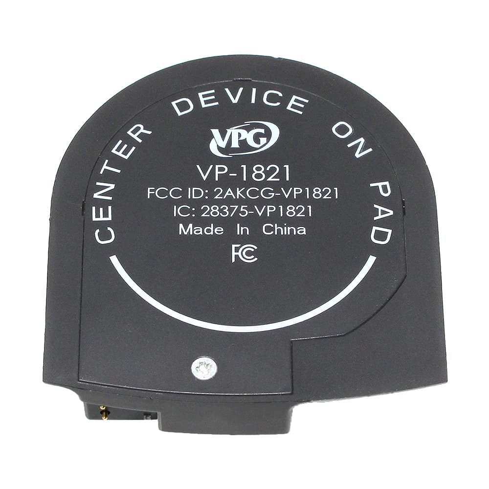
Click to zoom
Application Details
- Equipment Class
- 8CC - Part 18 Consumer Device
- Date of Grant
- Jul 10, 2023
- Application Purpose
- Original Equipment
- Date of Application
- Jul 10, 2023
- Equipment Note
- Inductive Charging Sensor
- Frequency Range
- 0.11000000 - 0.20500000
- Company
- Vanguard Protex Global Inc.
- Country
- United States
Documents & Files
Document Text
Text extracted from the exhibit documents filed with the FCC. Open a document above to read the original.
Users Manual
Rev 07/10/23 | ©2021 Vanguard Protex Global Rev 07/10/23 | ©2023 Vanguard Protex Global Customer Care | 1-877-477-4874 International | +1-813-855-9639 vanguardprotexglobal.com POWERED BY INNOVATION. SECURED BY EXPERIENCE. Wireless Charging Installation Manual TITAN L2QD ©Rev 07/10/23 Vanguard Protex Global Customer Care | 1-877-477-4874 International | +1-813-855-9639 vanguardprotexglobal.com 1 5 2 3 4 TOOLS & PARTS NEEDED Phone Security Angled Pedestal Vertical Pedestal V-T99 TITAN L2QD Wireless Charging Installation Manual VP-1644 VP-1821 VP-1594# VP-1586# or VP-1710#-3 V-T900 V-T30 V-39 V-T99 V-T41 K-1120 * = Optional | # = Substitute W for White Both Angled and Vertical pedestals have the same installation steps. Lay the pedestal over the slot in the fixture and feed the power cable down. Hold the pedestal in place during this step. IMPORTANT: The thin power cable should NOT go through any of the holes on the plate. Using the 2 provided screws and the V-T99, screw the metal plate with the rubber padding (K-1120) facing away from the counter. Make sure the rubber plate is facing out. Insert the sensor cable into the pedestal and out through the center of the metal plate. The power cable should feed out the side of the mounting plate. The VP-1644 cable stopper is installed behind the fixture. Open the stopper with a V-T41 security driver. Close the stopper in the groove at the end of the cable and tighten the screw again. Loosen the security screw on the back of the bracket assembly with the V-T900 security driver. IMPORTANT: Ensure proper orientation of the wireless housing puck. The metal ledge should be facing the opposite side of the 2 pins on the charging pad. Place the charging pad on the bracket. ©Rev 07/10/23 Vanguard Protex Global Customer Care | 1-877-477-4874 International | +1-813-855-9639 vanguardprotexglobal.com 6 7 89 TITAN L2QD Wireless Charging Installation Manual Phone Security Place the device and bracket face down on a flat surface. This holds the arms in place while tightening the screw. Align the bracket to the center of the device. Tighten the screw on the back of the bracket assembly with the security driver. First, plug the wireless power coupler into the sensor. Than, slide the bracket onto the sensor until you hear a click. Plug the V-39 power supply into an AC outlet. Plug the V-39 cable into the barrel connector shown. The sensor will have a red LED light indicating it is receiving power. The wireless power coupler will have a white LED light whenever the phone is being charged. To release the bracket, insert the V-T30 driver into the bracket release. Turn gently counter- clockwise and slide the bracket off. IMPORTANT: Ensure proper orientation of the bracket. The metal ledge should be facing the top of the phone. ©Rev 07/10/23 Vanguard Protex Global Customer Care | 1-877-477-4874 International | +1-813-855-9639 vanguardprotexglobal.com LED Functionality & Best Practices TITAN L2QD Wireless Charging Installation Manual LED BehaviorTITAN L2QD Wireless Charging Status & Meaning Steady solid red on sensor LEDUnit is at rest, and receiving power Wireless power coupler LED is solid white.Unit is charging the device properly at rest Both the wireless power coupler LED and sensor LED are off Unit is not receiving power: sensor is being lifted OR the unit is not connected to the V-39 power supply OR the power supply is not plugged into a live outlet Wireless power coupler LED is flashing white The unit is not properly charging the device; the device should be reoriented Sensor LED is solid red and the wireless power coupler’s LED is off Bracket assembly is not firmly seated and locked into the sensor OR the device is not properly oriented in the bracket assembly The Titan L2QD charges the device when at rest. When the device is lifted both LEDs will be off. When the device is resting on the pedestal, both LED's should be on (see chart for more details). For best results, make sure the bracket is evenly centered on the device. If the wireless power coupler LED is flashing white, the charging pad is not properly aligned with the device. Loosen the bracket arms and reorient the device on bracket until the LED is solid white while at rest. Proper Bracket Alignment FCC REGULATIONS - THIS DEVICE COMPLIES WITH PART 18 OF THE FCC RULES. OPERATION IS SUBJECT TO THE FOLLOWING TWO CONDITIONS: (1) THIS DEVICE MAY NOT CAUSE HARMFUL INTERFERENCE, AND (2) THIS DEVICE MUST ACCEPT ANY INTERFERENCE RECEIVED, INCLUDING INTERFERENCE THAT MAY CAUSE UNDESIRED OPERATION. NOTE: THE GRANTEE IS NOT RESPONSIBLE FOR ANY CHANGES OR MODIFICATIONS NOT EXPRESSLY APPROVED BY THE PARTY RESPONSIBLE FOR COMPLIANCE. SUCH MODIFICATIONS COULD VOID THE USER’S AUTHORITY TO OPERATE THE EQUIPMENT. ISED: THIS DEVICE CONTAINS LICENSE-EXEMPT TRANSMITTER(S)/RECEIVER(S) THAT COMPLY WITH INNOVATION, SCIENCE AND ECONOMIC DEVELOPMENT CANADA’S LICENSE-EXEMPT RSS(S). OPERATION IS SUBJECT TO THE FOLLOWING TWO CONDITIONS: 1. THIS DEVICE MAY NOT CAUSE INTERFERENCE. 2. THIS DEVICE MUST ACCEPT ANY INTERFERENCE, INCLUDING INTERFERENCE THAT MAY CAUSE UNDESIRED OPERATION OF THE DEVICE. CET APPAREIL CONTIENT UN OU DES ÉMETTEURS/RÉCEPTEURS EXEMPTS DE LICENCE CONFORMES AUX RSS EXEMPTS DE LICENCE D'INNOVATION, SCIENCES ET DÉVELOPPEMENT ÉCONOMIQUE CANADA. SON FONCTIONNEMENT EST SOUMIS AUX DEUX CONDITIONS SUIVANTES : 1. CET APPAREIL NE DOIT PAS PROVOQUER D'INTERFÉRENCES. 2. CET APPAREIL DOIT ACCEPTER TOUTES LES INTERFÉRENCES, Y COMPRIS LES INTERFÉRENCES POUVANT ENTRAÎNER UN FONCTIONNEMENT INDÉSIRABLE DE L'APPAREIL.
Attestation Statements
Rev 1/26/2023 Federal Communications Commission Authorization and Evaluation Division 7435 Oakland Mills Road Columbia, MD 21046 USA Date: 06-22-2023 Ref: Attestation Statements Part 2.911(d)(5)(i) Filing FCC ID: 2AKCG-VP1821 The applicant, Vanguard Protex Global Inc., certifies that the equipment for which authorization is sought is not “covered” equipment prohibited from receiving an equipment authorization pursuant to section 2.903 of the FCC rules. Sincerely, John S. Crawford Jr. Quality Manager Vanguard Protex Global Inc. Oldsmar, FL 34677 Rev 1/26/2023 Federal Communications Commission Authorization and Evaluation Division 7435 Oakland Mills Road Columbia, MD 21046 USA Date: 06-22-2023 Ref: Attestation Statements Part 2.911(d)(5)(ii) Filing FCC ID: 2AKCG-VP1821 The applicant, Vanguard Protex Global Inc., certifies that, as of the date of the filing of the application, the applicant is not identified on the Covered List as an entity producing “covered” equipment. Sincerely, John S. Crawford Jr. Quality Manager Vanguard Protex Global Inc. Oldsmar, FL 34677
Attestation Statements
Rev 1/26/2023 Federal Communications Commission Authorization and Evaluation Division 7435 Oakland Mills Road Columbia, MD 21046 USA Date: 06-22-2023 Ref: Attestation Statements Part 2.911(d)(7) Filing FCC ID or Grantee Code: 2AKCG-VP1821 The applicant certifies that, as of the date of the filing of the application, we designate ourselves as the U.S. agent for service of process. Designated U.S. Agent Information: FRN: 0025999137 Name: Vanguard Protex Global Inc. Address: 720 Brooker Creek Blvd. Suite 223, Oldsmar, FL 34677 USA Contact Person: John Crawford Tel.: 813-855-9639 ext. 135 Email: [email protected] Sincerely, John S. Crawford Jr. Quality Manager Vanguard Protex Global Inc. Oldsmar, FL 34677
Cover Letter(s)
May 18, 2023 Federal Communications Commission Authorization and Evaluation Division Confidentiality Request regarding application for certification of FCC ID: 2AKCG-VP1821. Pursuant to Sections 0.457 and 0.459 of the Commission’s Rules, we hereby request confidential treatment of information accompanying this application as outlined below: Exhibit Type Block and Schematics: •8069-0003-01-RevD_Schematic_BlockDiagram__To-TIMCO_2023200508 •8069-0003-01-RevD_Schematic_CircuitDiagram__To-TIMCO_2023200508 Circuit description: “VP-1821_CircuitDescription_20230508a” The above materials contain trade secrets and proprietary information not customarily released to the public. The public disclosure of these materials may be harmful to the applicant and provide unjustified benefits to its competitors. The applicant understands that pursuant to Section 0.457 of the Rules, disclosure of this application and all accompanying documentation will not be made before the date of the Grant for this application. Pursuant to DA04-1705 June 15, 2004 of the Commission’s public notice, we also request temporary confidential treatment of information accompanying this application as outlined below for 180 days Exhibit Type Test Set Up Photos External Photos Internal Photos User manual: “Installation Guide - Titan L2QD Wireless Charging” Sincerely, John S. Crawford Jr.
Cover Letter(s)
Date: 05/18/2023 TIMCO ENGINEERING, INC. 849 NW State Road 45 Newberry, FL 32669 SUBJECT: Application for Certification for FCC ID: 2AKCG-VP1821 IC: 28375-VP1821 To Whom It May Concern: We, the undersigned, hereby authorize Sharon Hoffman at Timco Engineering Inc. on our behalf, to apply to the Federal Communications Commission and ISED on our equipment. Any and all acts carried out by Sharon Hoffman at Timco Engineering Inc. on our behalf shall have the same effect as acts of our own. This is to advise that we are in full compliance with the Anti- Drug Abuse Act. We, the applicant, are not subject to a denial of federal benefits pursuant to Section 5301 of the Anti-Drug Act of 1988, 21 USC853a, and no party to the application is subject to a denial of federal benefits pursuant to that section. Regards, John S. Crawford Jr. Quality Manager Vanguard Protex Global Inc. Oldsmar, FL 34677
ID Label/Location Info
A B C D 1 2 3 4 A B C D 1 2 3 4 ⌀2.047 ⌀1.941 ⌀1.872 ⌀.110 .205 .050 .723 .120 .122 .080 PART NUMBER COLOR TABLE COMPONENT P/NCOLOR 8069-1032-00BLACK, PANTONE 3C 8069-1032-01 WHITE, RAL CLASSIC 9003P TINUVIN-329 UV PROTECTANT REV 8069-1032-XXB UNITS: INCH C SCALE: 1.000 DRAWING NUMBER:SIZESHEET: 1 OF 1 (813) 855-9639 720 Brooker Creek Blvd, Suite 223 Oldsmar, FL 34677 VANGUARD PROTEX GLOBAL. L2QD Qi Coil Bottom HSG NAME: PRO/ENGINEER STATE: Released .XXX= .125.XXX= .005 .XX= .25.XX= .02 .X= .5.X= .1 ANGULARDECIMAL DIMENSIONAL UNITS & TOLERANCES UNLESS OTEHRWISE SPECIFIED INTERPRET PER ANSI Y14.5 DO NOT SCALE DRAWING THE CONTENTS OF THIS DOCUMENT ARE "INTELLECTUAL PROPERTY OF VANGUARD PROTEX GLOBAL" WHICH ARE PROPRIETARY AND CONFIDENTIAL AND MAY NOT BE DIVULGED IN WHOLE OR PART WITHOUT AUTHORIZED PERMISSION OF VANGUARD PROTEX GLOBAL. CHECKED BYPREPARED BYDATEREVISIONSECNREV JJ10-JUN-2022RELEASED (DFM UPDATES 11JUL2022)-A DSJJ13-SEP-2022REINFORCED RIB, ADDED PRINT0738B SJJJ3-APR-2023UPDATED PRINT COLOR0770C DIMENSIONS THAT ARE BALLOONED/CIRCLED ARE DESIGNATED AS "CRITICAL" TO FUNCTION AND ARE TO BE INSPECTED TO ASSURE COMPLIANCE TO THE SPECIFICATION. DRAWING IS OF A CREO PARAMETRIC 3D CAD MODEL. CREO OR EXCHANGE CAD DATA SUCH AS IGES & STEP CONTAIN DIMENSIONAL DATA WHICH IS TO BE USED FOR PART AND TOOL FABRICATION. DRAWING DIMENSIONS AND NOTES SUPERSEDE THE CAD DATA. COPYRIGHT © 2022 VANGUARD PROTEX GLOBAL. ALL RIGHTS RESERVED. 1. MATERIAL: ABS (CHIMEI PA-707) 2. COLOR: SEE PART NUMBER COLOR TABLE 3. TEXTURE: MT-1055-02 ON EXTERNAL SURFACES 4. ALL EXTERIOR SURFACES TO BE FREE OF EJECTOR PIN MARKS, SINKS, VOIDS, WITNESS LINES, SPLAY AND OTHER MOLDING DEFECTS. 5. FLASH AND EJECTOR PIN MARKS ARE NOT TO EXCEED 0.005" 6. TOOL CONSTRUCTION AND MOLDING ARE TO MEET SPI AND PLASTIC INDUSTRY STANDARDS FOR QUALITY. 7. THIS DRAWING IS OF A CREO PARAMETRIC 3D SOLID CAD MODEL. THE CREO PART FILE OR EXCHANGE FILE SUCH AS IGES IS TO BE USED FOR TOOL CONSTRUCTION. 8. ALL INTERNAL CORNERS TO BE 0.01" MAX 9. ALL EXTERNAL CORNERS TO BE 0.01" MAX 10. REGRIND 0% 11. DO NOT USE MOLD RELEASE. 12. NO VISIBLE KNIT LINES OR FLOW MARKS ON FACE OF PRODUCT AREAS HIGHLIGHTED IN RED ARE TO BE TEXTURED SILK SCREEN OR PAD PRINT TEXT COLOR: PANTONE 428U TEXT 1. CENTER DEVICE ON PAD 2. VPG LOGO 3. FCC ID: 2AKCG-VP1821 4. IC: 28375-VP1821 5. MADE IN CHINA 6. ADD FCC LOGO
RF Exposure Info
Test Report# TR_8054-23_ FCC_1.1310(NS)_ Revision: 1 An IIA Company Te s t Report – FCC_1.1310 RF Exposure Applicant: Vanguard Protex Global Inc. Approved for Release By: Signature: Name & Title: Bruno Clavier, General Manager Date of Signature 6/22/2023 This test report shall not be reproduced except in full without the written and signed permission of Timco Engineering Inc. (IIA). This test report relates only to the items tested as identified and is not valid for any subsequent changes or modifications made to the equipment under test. Timco Engineering, Inc., an IIA Company 849 NW State Road 45, Newberry, Florida 32669 (352) 472-5500 / [email protected] Page 2 of 15 This test report shall not be reproduced except in full without the written and signed permission of Timco Engineering Inc. (IIA). Table of Contents 1. APPLICANT INFORMATION ........................................................................................................................................................................... 3 1.1 TEST RESULT SUMMARY ............................................................................................................................................................................................ 3 2. LOCATION OF TESTING ................................................................................................................................................................................. 4 2.1 TEST LABORATORY ....................................................................................................................................................................................................4 2.2 TESTING WAS PERFORMED, REVIEWED BY ................................................................................................................................................................4 3. TEST SAMPLE(S) (EUT/DUT) ........................................................................................................................................................................... 5 3.1 DESCRIPTION OF THE EUT ........................................................................................................................................................................................ 5 3.2 CONFIGURATION OF EUT ......................................................................................................................................................................................... 6 4. TEST METHODS & APPLICABLE REGULATORY LIMITS ............................................................................................................................ 7 4.1 TEST METHODS/STANDARDS/GUIDANCE ................................................................................................................................................................ 7 4.1.1 Limits for Maximum Permissible Exposure (MPE) ........................................................................................................................... 7 4.2 TEST EQUIPMENT LIST ............................................................................................................................................................................................... 8 4.3 EQUATIONS................................................................................................................................................................................................................ 9 5. RF EXPOSURE .................................................................................................................................................................................................. 10 5.1 NEAR FIELD MEASUREMENT ................................................................................................................................................................................... 10 5.1.1 0.001 – 400 kHz, Configuration 1, E-Field ....................................................................................................................................... 11 5.1.2 0.001 – 400 kHz, Configuration 1, H-Field ...................................................................................................................................... 12 5.1.3 0.001 – 400 kHz, Configuration 1, B-Field ....................................................................................................................................... 13 6. ANNEX-A - PHOTOGRAPHS OF THE EUT................................................................................................................................................ 14 7. ANNEX-B – TEST SETUP PHOTOGRAPHS ................................................................................................................................................ 14 8. HISTORY OF TEST REPORT CHANGES ...................................................................................................................................................... 14 Timco Engineering, Inc., an IIA Company 849 NW State Road 45, Newberry, Florida 32669 (352) 472-5500 / [email protected] Page 3 of 15 This test report shall not be reproduced except in full without the written and signed permission of Timco Engineering Inc. (IIA). 1. Applicant Information Applicant: Vanguard Protex Global Inc. Address: 720 Brooker Creek Blvd. Suite 223, Oldsmar, Florida, 34677, United States 1.1 Test Result Summary The following test procedure was used FCC 1.1310. Full test results are available in this report. No additions to the test methods were needed. There were no deviations, or exclusions from the test methods. No test results are from external providers or from the customer. The test results relate only to the items tested. Timco does not offer opinions and interpretations, only a pass/fail statement. Clauses Description of the Requirements Result (Pass, Fail or N/A) FCC 1.1310 Limits for Maximum Permissible Exposure (MPE) Pass T…
Text truncated - open the document above for the full version.
Test Report
Timco Test Report # TR_8054-23_FCC_18 _ Revision: 1 An IIA Company Te s t Report – FCC Par t 18 Applicant: Vanguard Protex Global Inc. Approved for Release By: Signature: Name & Title: Bruno Clavier, General Manager Date of Signature 6/22/2023 This test report shall not be reproduced except in full without the written and signed permission of Timco Engineering Inc. (IIA). This test report relates only to the items tested as identified and is not valid for any subsequent changes or modifications made to the equipment under test. Timco Engineering, Inc., an IIA Company 849 NW State Road 45, Newberry, Florida 32669 (352) 472-5500 / [email protected] Page 2 of 21 This test report shall not be reproduced except in full without the written and signed permission of Timco Engineering Inc. (IIA). Table of Contents 1. CUSTOMER INFORMATION ........................................................................................................................................................................... 3 1.1 TEST RESULT SUMMARY ............................................................................................................................................................................................ 3 2. LOCATION OF TESTING ................................................................................................................................................................................. 3 2.1 TEST LABORATORY .................................................................................................................................................................................................... 3 2.2 TES TING WAS PERFORMED, REVIEWED BY ................................................................................................................................................................4 3. TEST SAMPLE(S) (EUT/DUT) ........................................................................................................................................................................... 5 3.1 DESCRIPTION OF THE EUT ........................................................................................................................................................................................ 5 3.2 CONFIGURATION OF EUT ......................................................................................................................................................................................... 6 3.3 TEST SETUP OF EUT .................................................................................................................................................................................................. 6 4. TEST METHODS & APPLICABLE REGULATORY LIMITS ............................................................................................................................ 7 4.1 TEST METHODS/STANDARDS/GUIDANCE ................................................................................................................................................................ 7 5. MEASUREMENT UNCERTAINTY .................................................................................................................................................................... 7 6. ENVIRONMENTAL CONDITIONS ................................................................................................................................................................. 7 7. LIST OF TEST EQUIPMENT AND TEST FACILITY ........................................................................................................................................ 8 8. TEST RESULTS ................................................................................................................................................................................................... 9 8.1 RADIATED EMISSIONS.............................................................................................................................................................................................. 10 8.1.1 9 kHz to 150 kHz Plot ............................................................................................................................................................................ 11 8.1.2 150 kHz to 30 MHz Plot ....................................................................................................................................................................... 12 8.1.3 30 MHz to 200 MHz, Horizontal/ Vertical Polarity Plot .............................................................................................................. 13 8.1.4 200 MHz to 1000 MHz, Horizontal/ Vertical Polarity Plot .......................................................................................................... 14 8.2 CONDUCTED EMISSIONS ......................................................................................................................................................................................... 15 8.2.1 Line 1 Plot ................................................................................................................................................................................................. 16 8.2.2 Line 1 Table .............................................................................................................................................................................................. 17 8.2.3 Line 2 Plot ................................................................................................................................................................................................. 18 8.2.4 Line 2 Table .............................................................................................................................................................................................. 19 9. ANNEX-A - PHOTOGRAPHS OF THE EUT....................................................................…
Text truncated - open the document above for the full version.
Test Setup Photos
ANNEX B – Test Setup Photograph Exhibit Vanguard Protex Global Inc. Model: VP-1821 FCC ID: 2AKCG-VP1821 Radiated Testing, Table Setup Radiated Testing, Below 1 GHz #2 Radiated Testing, Below 1 GHz #3 AC Powerline Conducted Testing Nerve Stimulation Testing
Contact Information
Applicant
John Samuel Crawford(Quality Manager)
Test Firm
Timco Engineering, Inc.Bruno Clavier
Technical Specifications
| # | Rule Parts | Frequency Range | Power Output |
|---|---|---|---|
| 1 | 18 | 0.11 MHz - 0.205 MHz | - |