2AKHW-POCKETNFCUSB RFID-Reader
GMMC GmbH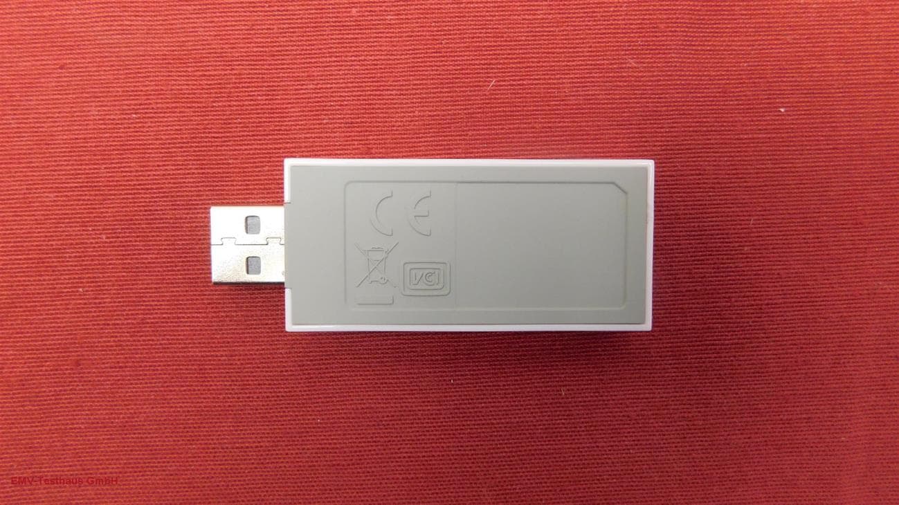
Click to zoom
Application Details
- Equipment Class
- DXX - Part 15 Low Power Communication Device Transmitter
- Date of Grant
- Jan 12, 2020
- Application Purpose
- Original Equipment
- Date of Application
- Jan 12, 2020
- Equipment Note
- USB RFID-Reader
- Frequency Range
- 13.56000000 - 13.56000000
- Company
- GMMC GmbH
- Country
- Austria
Documents & Files
Document Text
Text extracted from the exhibit documents filed with the FCC. Open a document above to read the original.
Users Manual
© 2019 GMMC GmbH Page 1 of 4 GMMC Pocket NFC Reader/Writer 13.56 MHz Multi Standard USB NFC Reader/Writer Manual version 1.2 Introduction The Pocket NFC reader/ writer is USB connected and powered and operates at 13.56 MHz. The Pocket NFC reader offers different tag related functionality and USB communication modes. If the tag is out of communication distance or if the communication is disturbed by harsh environmental noise, the implemented automatic tag detection reestablishes the reader-tag communication link Independent from the analog RF circuitry, responsible for RF performance and communication, three different digital USB host interface configurations are available. Pocket NFC Reader / Writer User Manual © 2019 by GMMC GmbH Page 2 of 4 USB VCOM (Virtual COM port) via CDC (communications device class) USB CCID (chip card interface device) is a USB protocol that allows a smartcard to be connected to a computer via a card reader. USB KBD (Keyboard) as part of the USB HID (human interface device class) specification for computer peripherals. It specifies a device class (a type of computer hardware) for human interface devices such as keyboards, mice, game controllers... Basic Reader behavior Once the reader device is connected and USB power is available the device boots up and switches the RF field on and starts automatic tag polling. The three board status LEDs (red/green/blue) are used to indicate different states, depending on the integrated firmware ́s function e.g. Power, RF polling, communication... Hardware Key features 1) 13.56MHz Multi Standard NFC Reader Writer o ISO/IEC 14443 incl. MIFARE products using Crypto 1 o ISO/IEC 15693 o ISO/IEC 18000-3 mode 3 o Full NFC Forum tag type o P2P active and passive, target, and initiator o Card emulation ISO14443 type A USB Stick form factor USB power USB digital communication modes o USB VCOM (CDC class) o USB KBD (Keyboard, HID class) o USB CCID (Chip Card Interface Device) Automatic tag discovery and communication link reconnection Note: Feature implementation (read only, read/write) depending on device firmware. RF parameters and analog circuitry behavior are not affected by the chosen USB host interface mode or functional firmware and are given by the analog RF circuitry. Pocket NFC Reader / Writer User Manual © 2019 by GMMC GmbH Page 3 of 4 Regulatory Statements Labelling requirements This device complies with part 15 of the FCC Rules. Operation is subject to the following two conditions: (1) This device may not cause harmful interference, and (2) this device must accept any interference received, including interference that may cause undesired operation. Information to the user Note: This equipment has been tested and found to comply with the limits for a Class B digital device, pursuant to part 15 of the FCC Rules. These limits are designed to provide reasonable protection against harmful interference in a residential installation. This equipment generates, uses and can radiate radio frequency energy and, if not installed and used in accordance with the instructions, may cause harmful interference to radio communications. However, there is no guarantee that interference will not occur in a particular installation. If this equipment does cause harmful interference to radio or television reception, which can be determined by turning the equipment off and on, the user is encouraged to try to correct the interference by one or more of the following measures: Reorient or relocate the receiving antenna. Increase the separation between the equipment and receiver. Connect the equipment into an outlet on a circuit different from that to which the Receiver is connected. Consult the dealer or an experienced radio/TV technician for help. Intended Use The device is intended to be used directly plugged into e.g. a PC, Laptop, USB bus extender, router or the likes. If the device is used with a USB extension cable, it is the responsibility of the user to select a cable that preserves compliance with the regulations applied. When connecting a USB extension cable, it is recommended to use one with a ferrite close to the device. Modification of equipment Changes or modifications made to this equipment not expressly approved by the party responsible for compliance may void the FCC authorization to operate this equipment. Notice This device contains licence-exempt transmitter(s)/receiver(s) that comply with Innovation, Science and Economic Development Canada’s licence-exempt RSS(s). Operation is subject to the following two conditions: (1) This device may not cause interference. (2) This device must accept any interference, including interference that may cause undesired operation of the device. Indication L’émetteur/récepteur exempt de licence contenu dans le présent appareil est conforme aux CNR d’Innovation, Sciences et Développement économique Canada applicables aux appareils radio exempts de licence. L’exploitation est autorisée aux deux conditions suivantes: (1) L’appareil ne doit pas produire de brouillage; (2) L’appareil doit accepter tout brouillage radioélectrique subi, même si le brouillage est susceptible d’en compromettre le fonctionnement. Pocket NFC Reader / Writer User Manual © 2019 by GMMC GmbH Page 4 of 4 Electrical and physical parameters Power supply USB bus powered 5.00 [V] (+0.25−0.60 V) Host Interface USB A connector Card polling After power up RF field is turned. A Tag discovery loop is started until communication between reader and tag is established. Optical interface 3 LEDS red, green, blue for status indication Operating temperature -10°C – +65°C Approvals FCC ID: 2AKHW-POCKETNFC IC: 22202-POCKETNFC CE label location: at bottom of device Supply Current < 80 mA (60 mA typ.) Physical Dimensions L x W x H 64 x 25 x 8.5 [mm] Note: MIFARE, MIFARE Classic, MIFARE DESFire, MIFARE Plus and NTAG are registered trademarks of NXP B.V.
Cover Letter(s)
Managing Director: DI Michael Ganzera | Company Registration Number: FN418591a, Tax #: ATU68813509, EORI Nr:ATEOS1000079439 Banking information: UniCredit Bank Austria AG (EURO): BIC/SWIFT code: BKAUATWW, IBAN: AT481200010008504317 Commercial Court: Landesgericht für Zivilrechtssachen Graz – Austria 1 GMMC GmbH Kehlbergstrasse 109 8054 Graz Austria UID/VAT: ATU68813509 EORI Nr.: ATEOS1000079439 Tel: +43 664 415-62-60 [email protected] To whom it may concern GMMC GmbH herewith confirms that the available USB host communication interface types USB-CCID, USB-CDC VCOM and USB-HID KBD have no influence on the RF parameters of the GMMC Pocket NFC Multi- Protocol reader/writer. The RF behavior is given by the analog RF matching circuitry and components and is not linked to the digital host communication interface. Graz, 12 December 2019 To whom it may concern
Cover Letter(s)
Long/Short-term Confidentiality Request PHOENIX TESTLAB GmbH Date: 16 December 2019 Product Certification Königswinkel 10 D 32825 Blomberg FCC ID: 2AKHW-POCKETNFC To Whom It May Concerns, Pursuant to sections 0.457(d) and 0.459 of CFR 47 and to avoid premature release of sensitive information prior to marketing or release of the product to the public, we hereby request long-term confidential treatment of information accompanying this application as outlined below: ☒ Schematics ☐ Parts List ☒ Block Diagram ☐ Tune-Up Info ☒ Operational Description In addition we hereby request the following exhibits contained in this application to be temporarily (short-term confidentiality) withheld from the public disclosure ☐ for an initial period of days ☐ until: ☒ not applicable ☐ External Photos ☐ Test Setup Photos ☐ Internal Photos ☐ Users Manual The above materials contain trade secrets and proprietary information not customarily released to the public. The public disclosure of these matters might be harmful to the applicant and provide unjustified benefits to its competitors. The applicant understands that pursuant to rule 0.457(d), disclosure of this application and all accompanying documentation will not be made before the date of the GRANT for this application. If you have any questions, please feel free to contact me. Yours sincerely, Christian Kiermeier Head of Laboratory
External Photos
EMV TESTHAUS GmbH Gustav-Hertz-Straße 35 94315 Straubing Germany Revision: 1.7 GMMC GmbH USB-Stick with RFID Pocket NFC Reader / Writer 180771-AU01+W01 Annex B Page 1 of 4 1 Annex B – EUT pictures external 1.1 List of Pictures Picture 1: EUT top side ...................................................................................................... 2 Picture 2: EUT bottom side ................................................................................................ 2 Picture 3: EUT front view – right side ................................................................................ 3 Picture 4: EUT rear view – right side ................................................................................. 3 Picture 5: EUT rear view – left side ................................................................................... 4 Picture 6: EUT front view – right side ................................................................................ 4 EMV TESTHAUS GmbH Gustav-Hertz-Straße 35 94315 Straubing Germany Revision: 1.7 GMMC GmbH USB-Stick with RFID Pocket NFC Reader / Writer 180771-AU01+W01 Annex B Page 2 of 4 Picture 1: EUT top side Picture 2: EUT bottom side EMV TESTHAUS GmbH Gustav-Hertz-Straße 35 94315 Straubing Germany Revision: 1.7 GMMC GmbH USB-Stick with RFID Pocket NFC Reader / Writer 180771-AU01+W01 Annex B Page 3 of 4 Picture 3: EUT front view – right side Picture 4: EUT rear view – right side EMV TESTHAUS GmbH Gustav-Hertz-Straße 35 94315 Straubing Germany Revision: 1.7 GMMC GmbH USB-Stick with RFID Pocket NFC Reader / Writer 180771-AU01+W01 Annex B Page 4 of 4 Picture 5: EUT rear view – left side Picture 6: EUT front view – right side
ID Label/Location Info
Managing Director: DI Michael Ganzera | Company Registration Number: FN418591a, Tax #: ATU68813509, EORI Nr:ATEOS1000079439 Banking information: UniCredit Bank Austria AG (EURO): BIC/SWIFT code: BKAUATWW, IBAN: AT481200010008504317 Commercial Court: Landesgericht für Zivilrechtssachen Graz – Austria GMMC GmbH Kehlbergstrasse 109 8054 Graz Austria UID/VAT: ATU68813509 Tel: +43 664 415-62-60 [email protected] FCC (USA) FRN: 0026043729 Grantee code: 2AKHW Product code: -POCKETNFC (GMMC defined) FCC ID: 2AKHW-POCKETNFC Industry Canada ISED CN: 22202 UPN: POCKETNFC PMN: Pocket NFC Reader / Writer HVIN: Pocket NFC ISED CERTIFICATION Nr: IC: 22202-POCKETNFC Label Location & Content Labels determining the provided USB Host interface USB-CCID USB-CDC VCOM USB-HID KBD Product information Pocket NFC 13.56MHz NFC Reader Writer
Internal Photos
EMV TESTHAUS GmbH Gustav-Hertz-Straße 35 94315 Straubing Germany Revision: 1.7 GMMC GmbH USB-Stick with RFID Pocket NFC Reader / Writer 180771-AU01+W01 Annex C Page 1 of 2 1 Annex C – EUT pictures internal 1.1 List of Pictures Picture 1: Top view of EUT without housing ...................................................................... 2 Picture 2: Rear view of EUT without housing..................................................................... 2 EMV TESTHAUS GmbH Gustav-Hertz-Straße 35 94315 Straubing Germany Revision: 1.7 GMMC GmbH USB-Stick with RFID Pocket NFC Reader / Writer 180771-AU01+W01 Annex C Page 2 of 2 Picture 1: Top view of EUT without housing Picture 2: Rear view of EUT without housing
Test Report
All test results relate to the items tested only. For reproduction of extracts of this test report, the written approval of EMV TESTHAUS GmbH is required. Applicant: GMMC GmbH Kehlbergstrasse 109 8054 Graz Tel.: +43 664 415 6260 Test report no.: 180771-AU01+W01 for: GMMC GmbH USB-Stick with RFID Pocket NFC Reader - Writer according to: 15.225 RSS-210 EMV TESTHAUS GmbH Gustav-Hertz-Straße 35 94315 Straubing Germany GMMC GmbH USB-Stick with RFID Pocket NFC Reader / Writer 180771-AU01+W01 Page 2 of 53 Accreditation: FCC test firm accreditation expiration date: 2021-05-30 MRA US-EU, FCC designation number: DE0010 FCC registration number: 97268 BnetzA-CAB-02/21-02/5 Valid until 2023-11-26 Recognized on March 14 th , 2019 by the Department of Innovation, Science and Economic Development (ISED) Canada as a wireless testing laboratory CAB identifier: DE0011 ISED#: 3472A Location of Testing: EMV TESTHAUS GmbH Tel.: +49 9421 56868-0 Fax: +49 9421 56868-100 Email: [email protected] Gustav-Hertz-Straße 35 94315 Straubing, Germany The technical accuracy is guaranteed through the quality management of the EMV TESTHAUS GmbH. EMV TESTHAUS GmbH Gustav-Hertz-Straße 35 94315 Straubing Germany GMMC GmbH USB-Stick with RFID Pocket NFC Reader / Writer 180771-AU01+W01 Page 3 of 53 Table of contents 1 Summary of test results ............................................................................................................ 5 2 Referenced publications ........................................................................................................... 7 3 Equipment under test (EUT) ..................................................................................................... 8 3.1 General information ........................................................................................................... 8 3.2 Radio specifications ........................................................................................................... 9 3.3 Photo documentation ......................................................................................................... 9 4 Test configuration and mode of operation ............................................................................... 10 4.1 Test configuration ............................................................................................................ 10 4.2 Mode of operation ............................................................................................................ 10 5 Test procedures...................................................................................................................... 11 5.1 General specifications ..................................................................................................... 11 5.2 AC power line conducted emission .................................................................................. 11 5.3 Radiated emissions below 30 MHz .................................................................................. 13 5.4 Radiated emissions from 30 MHz to 1 GHz ..................................................................... 15 5.5 Radiated emissions above 1 GHz .................................................................................... 18 5.6 Bandwidth measurements ............................................................................................... 21 5.7 Operation within the band 13.110 MHz - 14.010 MHz ...................................................... 22 5.8 Carrier frequency stability ................................................................................................ 22 6 Test results ............................................................................................................................. 23 6.1 AC powerline conducted emissions ................................................................................. 24 6.2 20 dB bandwidth .............................................................................................................. 30 6.3 Occupied bandwidth ........................................................................................................ 34 6.4 Operation within the band 13.110 MHz – 14.010 MHz ..................................................... 37 6.5 Carrier frequency stability ................................................................................................ 41 6.6 Emissions outside the operating frequency band(s) specified .......................................... 45 7 Equipment calibration status ................................................................................................... 51 8 Measurement uncertainties .................................................................................................... 52 9 Revision history ...................................................................................................................... 53 EMV TESTHAUS GmbH Gustav-Hertz-Straße 35 94315 Straubing Germany GMMC GmbH USB-Stick with RFID Pocket NFC Reader / Writer 180771-AU01+W01 Page 4 of 53 List of figures Figure 1: Setup for AC power-line conducted emissions test from 150 kHz to 30 MHz .................. 12 Figure 2: Setup for radiated emissions test below 30 MHz ............................................................ 15 Figure 3: Setup for radiated emissions test from 30 MHz to 1 GHz ............................................... 17 Figure 4: Setup for radiated emissions test above 1 GHz .............................................................. 20 Figure 5: Test setup for carrier frequency stability measurement ................................................... 22 Figure 6: Chart of AC powerline conducted emissions on L1 – without termination ....................... 26 Figure 7: Chart of AC powerline conducted emissions on N – without termination......................... 27 Figure 8: Chart of AC powerline conducted emissions on L1 – with termination ............................ 28 Figure …
Text truncated - open the document above for the full version.
Test Report
All test results relate to the items tested only. For reproduction of extracts of this test report, the written approval of EMV TESTHAUS GmbH is required. Applicant: GMMC GmbH Kehlbergstrasse 109 8054 Graz Tel.: +43 664 415 6260 Test report no.: 180771-AU01+W01 for: GMMC GmbH USB-Stick with RFID Pocket NFC Reader - Writer according to: 15.225 RSS-210 EMV TESTHAUS GmbH Gustav-Hertz-Straße 35 94315 Straubing Germany GMMC GmbH USB-Stick with RFID Pocket NFC Reader / Writer 180771-AU01+W01 Page 2 of 53 Accreditation: FCC test firm accreditation expiration date: 2021-05-30 MRA US-EU, FCC designation number: DE0010 FCC registration number: 97268 BnetzA-CAB-02/21-02/5 Valid until 2023-11-26 Recognized on March 14 th , 2019 by the Department of Innovation, Science and Economic Development (ISED) Canada as a wireless testing laboratory CAB identifier: DE0011 ISED#: 3472A Location of Testing: EMV TESTHAUS GmbH Tel.: +49 9421 56868-0 Fax: +49 9421 56868-100 Email: [email protected] Gustav-Hertz-Straße 35 94315 Straubing, Germany The technical accuracy is guaranteed through the quality management of the EMV TESTHAUS GmbH. EMV TESTHAUS GmbH Gustav-Hertz-Straße 35 94315 Straubing Germany GMMC GmbH USB-Stick with RFID Pocket NFC Reader / Writer 180771-AU01+W01 Page 3 of 53 Table of contents 1 Summary of test results ............................................................................................................ 5 2 Referenced publications ........................................................................................................... 7 3 Equipment under test (EUT) ..................................................................................................... 8 3.1 General information ........................................................................................................... 8 3.2 Radio specifications ........................................................................................................... 9 3.3 Photo documentation ......................................................................................................... 9 4 Test configuration and mode of operation ............................................................................... 10 4.1 Test configuration ............................................................................................................ 10 4.2 Mode of operation ............................................................................................................ 10 5 Test procedures...................................................................................................................... 11 5.1 General specifications ..................................................................................................... 11 5.2 AC power line conducted emission .................................................................................. 11 5.3 Radiated emissions below 30 MHz .................................................................................. 13 5.4 Radiated emissions from 30 MHz to 1 GHz ..................................................................... 15 5.5 Radiated emissions above 1 GHz .................................................................................... 18 5.6 Bandwidth measurements ............................................................................................... 21 5.7 Operation within the band 13.110 MHz - 14.010 MHz ...................................................... 22 5.8 Carrier frequency stability ................................................................................................ 22 6 Test results ............................................................................................................................. 23 6.1 AC powerline conducted emissions ................................................................................. 24 6.2 20 dB bandwidth .............................................................................................................. 30 6.3 Occupied bandwidth ........................................................................................................ 34 6.4 Operation within the band 13.110 MHz – 14.010 MHz ..................................................... 37 6.5 Carrier frequency stability ................................................................................................ 41 6.6 Emissions outside the operating frequency band(s) specified .......................................... 45 7 Equipment calibration status ................................................................................................... 51 8 Measurement uncertainties .................................................................................................... 52 9 Revision history ...................................................................................................................... 53 EMV TESTHAUS GmbH Gustav-Hertz-Straße 35 94315 Straubing Germany GMMC GmbH USB-Stick with RFID Pocket NFC Reader / Writer 180771-AU01+W01 Page 4 of 53 List of figures Figure 1: Setup for AC power-line conducted emissions test from 150 kHz to 30 MHz .................. 12 Figure 2: Setup for radiated emissions test below 30 MHz ............................................................ 15 Figure 3: Setup for radiated emissions test from 30 MHz to 1 GHz ............................................... 17 Figure 4: Setup for radiated emissions test above 1 GHz .............................................................. 20 Figure 5: Test setup for carrier frequency stability measurement ................................................... 22 Figure 6: Chart of AC powerline conducted emissions on L1 – without termination ....................... 26 Figure 7: Chart of AC powerline conducted emissions on N – without termination......................... 27 Figure 8: Chart of AC powerline conducted emissions on L1 – with termination ............................ 28 Figure …
Text truncated - open the document above for the full version.
Test Setup Photos
EMV TESTHAUS GmbH Gustav-Hertz-Straße 35 94315 Straubing Germany Revision: 1.7 GMMC GmbH USB-Stick with RFID Pocket NFC Reader / Writer 180771-AU01+W01 Annex A Page 1 of 7 1 Annex A – Test setup 1.1 List of Pictures Picture 1: EUT test setup radiated emission test 9 kHz – 30 MHz (front view) .................. 2 Picture 2: EUT test setup radiated emission test 9 kHz – 30 MHz (rear view) ................... 2 Picture 3: EUT test setup radiated emission test 30 MHz – 1 GHz (front view) ................. 3 Picture 4: EUT test setup radiated emission test 30 MHz – 1 GHz (rear view) .................. 3 Picture 5: EUT test setup conducted emission test (front view) ......................................... 4 Picture 6: EUT test setup conducted emission test (rear view) .......................................... 4 Picture 7: EUT Position 1................................................................................................... 5 Picture 8: EUT Position 2................................................................................................... 5 Picture 9: EUT Position 3................................................................................................... 6 Picture 3: RFID tag 13.56 MHz .......................................................................................... 6 Picture 4: USB cable with ferrite ........................................................................................ 7 EMV TESTHAUS GmbH Gustav-Hertz-Straße 35 94315 Straubing Germany Revision: 1.7 GMMC GmbH USB-Stick with RFID Pocket NFC Reader / Writer 180771-AU01+W01 Annex A Page 2 of 7 Picture 1: EUT test setup radiated emission test 9 kHz – 30 MHz (front view) Picture 2: EUT test setup radiated emission test 9 kHz – 30 MHz (rear view) EMV TESTHAUS GmbH Gustav-Hertz-Straße 35 94315 Straubing Germany Revision: 1.7 GMMC GmbH USB-Stick with RFID Pocket NFC Reader / Writer 180771-AU01+W01 Annex A Page 3 of 7 Picture 3: EUT test setup radiated emission test 30 MHz – 1 GHz (front view) Picture 4: EUT test setup radiated emission test 30 MHz – 1 GHz (rear view) EMV TESTHAUS GmbH Gustav-Hertz-Straße 35 94315 Straubing Germany Revision: 1.7 GMMC GmbH USB-Stick with RFID Pocket NFC Reader / Writer 180771-AU01+W01 Annex A Page 4 of 7 Picture 5: EUT test setup conducted emission test (front view) Picture 6: EUT test setup conducted emission test (rear view) EMV TESTHAUS GmbH Gustav-Hertz-Straße 35 94315 Straubing Germany Revision: 1.7 GMMC GmbH USB-Stick with RFID Pocket NFC Reader / Writer 180771-AU01+W01 Annex A Page 5 of 7 Picture 7: EUT Position 1 Picture 8: EUT Position 2 EMV TESTHAUS GmbH Gustav-Hertz-Straße 35 94315 Straubing Germany Revision: 1.7 GMMC GmbH USB-Stick with RFID Pocket NFC Reader / Writer 180771-AU01+W01 Annex A Page 6 of 7 Picture 9: EUT Position 3 Picture 10: RFID tag 13.56 MHz EMV TESTHAUS GmbH Gustav-Hertz-Straße 35 94315 Straubing Germany Revision: 1.7 GMMC GmbH USB-Stick with RFID Pocket NFC Reader / Writer 180771-AU01+W01 Annex A Page 7 of 7 Picture 11: USB cable with ferrite
Contact Information
Applicant
Michael Ganzera(General Manager)
Test Firm
Element Materials Technology Straubing GmbHChristian Kiermeier
Technical Specifications
| # | Rule Parts | Frequency Range | Power Output | Tolerance |
|---|---|---|---|---|
| 1 | 15C | 13.56 MHz - 13.56 MHz | - | 0.0100000000 % |