2AKKSE40Baby Monitor Display
Shenzhen HDKing Electronics Co.,Ltd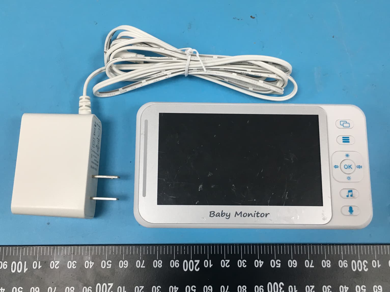
Click to zoom
Application Details
- Equipment Class
- DSS - Part 15 Spread Spectrum Transmitter
- Date of Grant
- Jul 09, 2020
- Application Purpose
- Original Equipment
- Date of Application
- Jul 09, 2020
- Equipment Note
- Baby Monitor Display
- Frequency Range
- 2410.00000000 - 2469.50000000
- Country
- China
Documents & Files
Document Text
Text extracted from the exhibit documents filed with the FCC. Open a document above to read the original.
Users Manual
User Manual We have tried our best to ensure that the contents of this manual are correct and latest. However, there is no guarantee that everything is correct. If the contents of this manual do not conform to the current product, please follow this product. We reserve the right to change the content or technical specifications without prior notice. If the accessories do not match the items in the actual package, please follow the actual package. Instructions for the use of baby monitors Thank you for buying our products, This manual provides you the monitor information and methods of using the monitor. 1. Safety instruction 1.1 this baby monitor is not a substitute for responsible adult supervision. 1.2 this product shall be placed in a place that is not accessible to the baby and shall be kept in a distance of at least 1.5 m from the baby to ensure that the baby has a corresponding safe range with the product. 1.3 DC power should not be placed where baby can touch, avoid to wind the child's body parts and cause baby safety problems. 1.4 this product is not a toy and children are not allowed to play with it. 1.5 use the correct power adapter: output 5V/1A Products Appearance TX Camera 1. Camera 2.power light 3.IR sensor 4.IR light 5.Microphone hole 6.Mat 7.Speaker 8.antenna 9.DC Power port 10.Pair code key 11.temperature sensor 12.Bracket Handheld display 1.Power port 2.Power indicator and voice volume lamp 3.boot Key 4.Camera switching key 5.Menu Key 6.OK key 7.direction key 8.Music key 9.Intercom key 10.Reset Key 11.Speaker 12.Bracket 13.battery cover 14.antenna 15.LCD Button introduction 1.Power On / off key: long press to turn on/off machine and short press to turn off the screen after boot 2.Ok key: implement menu execution instructions 3.Pair code key :Perform the pairing effect of the camera on the code 4.Menu / return key: implement the pop-up of the menu, as well as the return of each submenu to the next level 5.Up key: realize menu setting item up option scroll. And a quick increase in screen brightness. 6.Down key: implement menu settings to scroll down options. And a quick decline in screen brightness. 7.Left key: realizes the left movement of the menu setting item. And the quick decline of volume. 8.Right key: realizes the right movement of the menu setting item. And the quick increase of volume 9.Intercom key: in the monitoring screen, long press this key to realize the intercom function 10.Camera switching key: achieve camera switching, lock a single camera monitoring, and achieve two camera cycle monitoring functions 11.Music on / off shortcut key: quickly turn on and off music in the monitoring screen. When the music is turned on, the short press to switch the music. 12 Reset key: once pressing the boot key is invalid and cannot be used normally. You can press the reset key lightly and then press the boot key to turn on normally. Button introduction 1. TX camera 1.1 This machine uses DC adapter with output 5V/1A 1.2 Power the device on and the blue led indicator lights on, indicating that the machine is turned on and is working Note: Use only the supplied power adapter. 1.3 Night vision: the baby device has 10 infrared light, which are used to complement the light in the dark, and the user gets a clear image. 1.4 Turn on and off the infrared light: on working mode, the infrared light can be turned on and off automatically through the dark and bright light of the environment, so as to increase the amount of light fed by the camera and achieve the supplementary light effect in the dark state of the image, so that the user can view the best image. 1.5 please place this device within the range of baby monitoring, and the camera is aimed at the area you want to monitor. Don't put the machine where the baby reaches out and get it, so as to avoid strangling the power cable to the baby and causing asphyxiation 1.6 If the image or sound is disturbed, try moving the device to a different location for debugging to the best effect。 1.7 when the first to use, you need to match it successfully before you can use it. For more information on pairing, see the details page for adding cameras to 2.5.5 cameras. 2.RX display 2.1 This machine is powered by a 3.7v lithium battery or a DC ad apter output of 5V/1A, The power Adapter can be used for charging when the lithium battery is low Note: Use only the supplied power adapter. 2.2Turn on the device and long press the boot key ,then enter into the initial system screen. 2.3This machine can support two cameras to monitor 2.4The monitor screen icon is shown in the following figure 2.4.1) signal strength indication 2.4.2) The present camera icon (press the switch key to switch. 1 for the first camera and 2 for the second camera) 2.4.3) Locking a single camera monitor icon (press the switch key to switch, when switching to circular monitoring, the icon prompt will be changed. Switching to this icon it means a circular monitoring) 2.4.4) The music icon , the device has 8 pieces of music totally, and the user select #1 - 8 as a single loop, and if you select 9, all the musics will be loop played. 2.4.5) speaker icon 2.4.6) temperature for baby room, (Fahrenheit or Celsius can be choosed on the menu) 2.4.7) Time icon(AM means morning, PM means afternoon) 2.4.8) battery icon Menu Option The menu options are shown in the following figure Press menu / return key to pop-up menu, which contains 6 items: 2.5.1) Breast-feeding reminder setting 2.5.2) Music selection setting 2.5.3) Time setting 2.5.4) Temperature setting 2.5.5) Camera setting 2.5.6) Voice control setting You can select the menu by right or left key to move the Cursor , Press the up and down keys to make the selection. then Press the ok key to confirm. Press the menu/ return key to exit the setup menu 2.5.1 Breast-feeding reminder setting Enter the feeding reminder setting, there are 5 alarms to choose from the following figure. Select the breast-feeding reminder setting up, press the up an…
Text truncated - open the document above for the full version.
External Photos
EXHIBIT B - EUT EXTERNAL PHOTOGRAPHS Adapter
ID Label/Location Info
EXHIBIT A - FCC ID LABEL AND LOCATION FCC ID Label FCC ID Label Location Information The label shown shall be permanently affixed at a conspicuous location on the device and be readily visible to the user at the time purchase (Labeling requirements per 2.925)
Internal Photos
EXHIBIT C - EUT INTERNAL PHOTOGRAPHS IC Antenna Battery
RF Exposure Info
Bay Area Compliance Laboratories Corp. (Shenzhen) Report No.: RSZ200324811-00 FCC Part 15.247 Page 10 of 39 FCC §15.247 (i) & §2.1091- MAXIMUM PERMISSIBLE EXPOSURE (MPE) Applicable Standard According to subpart 15.247 (i) and subpart 2.1091 systems operating under the provisions of this section shall be operated in a manner that ensures the public is not exposed to RF energy level in excess of the communication guidelines. Limits for General Population/Uncontrolled Exposure Limits for General Population/Uncontrolled Exposure Frequency Range (MHz) Electric Field Strength (V/m) Magnetic Field Strength (A/m) Power Density (mW/cm 2 ) Averaging Time (Minutes) 0.3-1.34 614 1.63 *(100) 30 1.34-30 824/f 2.19/f *(180/f 2 ) 30 30-300 27.5 0.073 0.2 30 300-1500 / / f/1500 30 1500-100,000 / / 1.0 30 f = frequency in MHz * = Plane-wave equivalent power density Result Calculated Formulary: Predication of MPE limit at a given distance S = 2 4R PG S = power density (in appropriate units, e.g. mW/cm2) P = power input to the antenna (in appropriate units, e.g., mW). G = power gain of the antenna in the direction of interest relative to an isotropic radiator, the power gain factor, is normally numeric gain. R = distance to the center of radiation of the antenna (appropriate units, e.g., cm) Frequency (MHz) Antenna Gain Max Tune Up Conducted Power Evaluation Distance (cm) Power Density (mW/cm 2 ) MPE Limit (mW/cm 2 ) (dBi) (numeric) (dBm) (mW) 2410-2469.5 3.18 2.08 12.0 15.85 20 0.007 1.0 Note: To maintain compliance with the FCC’s RF exposure guidelines, place the equipment at least 20cm from nearby persons. Result: compliance.
Test Report
Note: This report must not be used by the customer to claim product certification, approval, or endorsement by A2LA* or any agency of the Federal Government. This report may contain data that are not covered by the A2LA accreditation and are marked with an asterisk “★”. BACL is not responsible for the authenticity of any test data provided by the applicant. Data included from the applicant that may affect test results are marked with an asterisk ’*’. Customer model name, addresses, names, trademarks etc. are not considered data. This report cannot be reproduced except in full, without prior written approval of the Company. Unless otherwise stated the results shown in this test report refer only to the sample(s) tested. This report is valid only with a valid digital signature. The digital signature may be available only under the Adobe software above version 7.0. FCC PART 15.247 TEST REPORT For Shenzhen HDKing Electronics Co.,Ltd Room 101 Building 1, Huasen Factory, No.142 Honghu Road, Yanluo Street, Baoan District, Shenzhen, China FCC ID: 2AKKSE40 Report Type: Original Report Product Type: Baby monitor display Re port Number: RSZ200324811-00 Re port Date: 2020-06-09 Reviewed B y: Jimmy Xiao RF En gineer Prepared By: Bay Area Compliance Laboratories Corp. (Shenzhen) 6/F., West Wing, Third Phase of Wanli Industrial Building, Shihua Road, Futian Free Trade Zone, Shenzhen, Guangdong, China Tel: +86-755-33320018 Fax: +86-755-33320008 www.baclcorp.com.cn Bay Area Compliance Laboratories Corp. (Shenzhen) Report No.: RSZ200324811-00 FCC Part 15.247 Page 2 of 39 TABLE OF CONTENTS GENERAL INFORMATION ....................................................................................................................................... 4 PRODUCT DESCRIPTION FOR EQUIPMENT UNDER TEST (EUT) ..................................................................................... 4 OBJECTIVE ................................................................................................................................................................... 4 RELATED SUBMITTAL(S)/GRANT(S) ............................................................................................................................. 4 TEST METHODOLOGY .................................................................................................................................................. 4 MEASUREMENT UNCERTAINTY .................................................................................................................................... 5 TEST FACILITY ............................................................................................................................................................. 5 SYSTEM TEST CONFIGURATION .......................................................................................................................... 6 DESCRIPTION OF TEST CONFIGURATION ...................................................................................................................... 6 EUT EXERCISE SOFTWARE .......................................................................................................................................... 6 SPECIAL ACCESSORIES ................................................................................................................................................. 6 EQUIPMENT MODIFICATIONS ....................................................................................................................................... 6 SUPPORT EQUIPMENT LIST AND DETAILS .................................................................................................................... 6 EXTERNAL I/O CABLE .................................................................................................................................................. 7 BLOCK DIAGRAM OF TEST SETUP ................................................................................................................................ 7 SUMMARY OF TEST RESULTS ............................................................................................................................... 8 TEST EQUIPMENT LIST ........................................................................................................................................... 9 FCC §15.247 (i) & §2.1091- MAXIMUM PERMISSIBLE EXPOSURE (MPE) ........................................................ 10 APPLICABLE STANDARD ............................................................................................................................................ 10 RESULT ...................................................................................................................................................................... 10 FCC §15.203 – ANTENNA REQUIREMENT .......................................................................................................... 11 APPLICABLE STANDARD ............................................................................................................................................ 11 ANTENNA CONNECTOR CONSTRUCTION .................................................................................................................... 11 FCC §15.207 (a) – AC LINE CONDUCTED EMISSIONS ..................................................................................... 12 APPLICABLE STANDARD ............................................................................................................................................ 12 EUT SETUP ................................................................................................................................................................ 12 EMI TEST RECEIVER SETUP ....................................................................................................................................... 12 TEST PROCEDURE .......................................................................................................…
Text truncated - open the document above for the full version.
Test Setup Photos
EXHIBIT D - TEST SETUP PHOTOGRAPHS Conducted Emissions - Front View Conducted Emissions - Side View Radiated Emissions View (Below 1 GHz) Radiated Emissions View (Above 1 GHz)
Contact Information
Applicant
Jerry Kung(Sales Director)
Test Firm
Bay Area Compliance Laboratories Corp. (Shenzhen)Well Wang
[email protected]+86 (0) 755 33320018
Technical Specifications
| # | Rule Parts | Frequency Range | Power Output |
|---|---|---|---|
| 1 | 15C | 2.41 GHz - 2.47 GHz | 14.00 mW |
Other Applications from Shenzhen HDKing Electronics Co.,Ltd
2AKKS-BM06A-V
Dec 14, 2023Baby Monitor
Equipment Class
DTS - Digital Transmission System
2AKKS-30J2CW
Apr 03, 2023Hunting Camera
Equipment Class
DTS - Digital Transmission System
2AKKS-NDL703P
May 24, 2021Hunting camera
Equipment Class
DTS - Digital Transmission System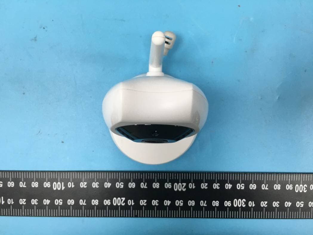
2AKKSBM02
Jul 09, 2020Baby Monitor Camera
Equipment Class
DSS - Part 15 Spread Spectrum Transmitter