2AKWRD1-Bwireless Water Timer
LinkTap Pty Ltd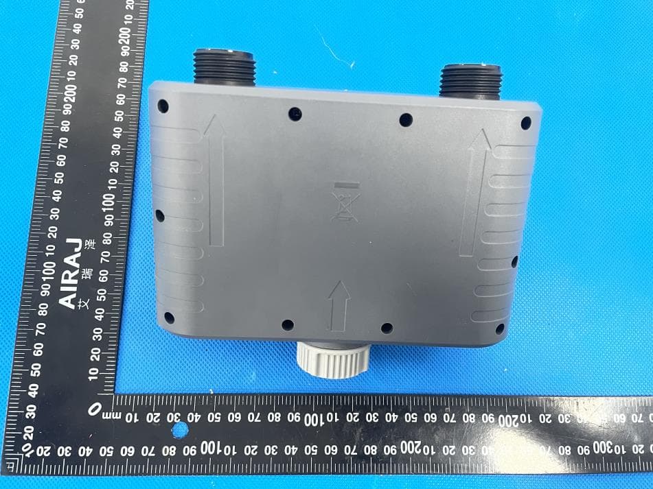
Click to zoom
Application Details
- Equipment Class
- DTS - Digital Transmission System
- Date of Grant
- Jun 12, 2022
- Application Purpose
- Original Equipment
- Date of Application
- Jun 12, 2022
- Equipment Note
- wireless Water Timer
- Frequency Range
- 2405.00000000 - 2480.00000000
- Company
- LinkTap Pty Ltd
- Country
- Australia
Documents & Files
Document Text
Text extracted from the exhibit documents filed with the FCC. Open a document above to read the original.
Users Manual
D1 User Manual The LinkTap Wireless Water Timer is designed for private use in domestic gardens to control sprinklers and watering systems through the LinkTap app. The LinkTap's device must not be used for industrial purposes or in conjunction with chemicals, dirty water, or easily flammable and explosive substance. Use 4 AA alkaline or 1.5V lithium batteries (not included). Good quality 1.5V Li-ion rechargeable batteries can also be used. Do not use carbon-zinc batteries. Remove the timer from the faucet during freezing weather and store inside. Timer should not be submerged in water, used in damp pits or buried. --------------------------------------------------------------------------------------------------- Installation Step 1: Connect LinkTap Gateway to a LAN port of your home broadband modem (or a network switch, a router, a hub, a Wi-Fi extender) using the supplied ethernet cable. Power on the Gateway using the supplied USB cord and power adapter. 3 solid green LEDs (Power, Link and Internet) indicate that the Gateway has connected to the LinkTap cloud server. This process may take up to a few minutes. To reduce possible interference, please place the Gateway over 30cm (or 1 foot) away from any power sockets and/or other electronic devices. Tip: Placing the Gateway at a higher location will usually increase the wireless coverage. Step 2: Register the Gateway through LinkTap free mobile app or web app. When the registration is completed, the Synced LED on the Gateway will turn solid green. Step 3: Add a new D1 TapLinker (i.e., D1 wireless water timer) through LinkTap app. there will be 2 or 4 ValveLinkers displayed on the app, and each of the ValveLinkers can be controlled independently. Step 4: Insert 4 AA alkaline batteries into the TapLinker in the correct orientation and switch it on. The TapLinker will automatically connect to the Gateway in 5~60 seconds, as indicated by 2 solid green LEDs ( and ). These 2 LEDs will go off after being solid green for 15 seconds to save power. The LinkTap D1 water timer contains an inclination sensor to detect changes in the tilt angle of the device. If the angle change exceeds a certain threshold, the system will register that the water timer has fallen off the faucet. You can verify the fall detection and notification process of your LinkTap water timer by following the steps below. 1) On the Device Details page, check if “TapLinker fall alert” has been disabled. If not, disable it. 2) Place the watering timer upright on a desktop, then enable the “TapLinker fall alert” in the app. 3) Lay the watering timer flat on the desktop. Within 45 seconds, you should receive a TapLinker fall alert on your phone. 4) Disable the “TapLinker fall alert” in the app to continue the product installation process. Step 5: Screw the TapLinker to your garden tap firmly by hand to prevent leaks. At this point, you can verify the water cut-off detection and notification process by following the steps below: 1) Enable "Water cut-off alert" on the app; 2) Turn off the faucet completely and make ensure that no water flows out of the faucet; 3) Press the Manual On/Off button on the device, or activate Instant mode on the app to start watering. Within 45 seconds, you should receive a water cut-off alert on your phone. Manual Watering Press the blue Manual On/Off button once to start or stop watering. You can also disable, partially enable or fully enable the Manual button lockout function through the app. Step 6: Enable all fault alert options on the app. You can now remotely access your wireless water timer with peace of mind! About the fault detection function: Your LinkTap water timer contains an inclination sensor and a flow meter sensor. Apart from being able to measure flow rate in real time, the device can detect the following faults in a real time manner and then send push notifications and emails to you and your nominated person, e.g. neighbor, friends, etc. 1) The water timer falls off the faucet; 2) The water timer failed to shut down the watering properly; 3) The water timer failed to open the valve properly; 4) The mains water is turned off, causing no water come out of the water timer; 5) The water flow rate abnormally increases or decreases. The real-time push notifications will be sent to all your smartphones and tablets with the LinkTap app installed, and an email will be sent to your registered email address and two other email addresses. You can use email address of your neighbors, friends, family members, or colleagues, so that when a fault occurs but you are unable to handle the failure in time for some reason, they can help you out. When a fault occurs, in order to avoid false positives, the system will make multiple measurements, so sending out real-time push notifications and emails will be delayed by 10 to 45 seconds. Similarly, when the flow rate changes, the current flow rate value won’t be shown on the app until 10 to 30 seconds later. --------------------------------------------------------------------------------------------------- Specifications Operating water pressure range: 0.02-0.8MPa or 2.9-116 psi Watering cycles per day: up to 100 Watering duration per cycle: 3 seconds to 23 hours 59 minutes Temperature of water flow: 1°C to 40°C Flow meter measurement range: 2 to 50 L/min with a measurement error of ± 5% Wireless water timer power: 4 AA alkaline or 1.5V lithium batteries Gateway power input: 5V DC, 1A Wireless technology: Zigbee Wireless transmission distance: up to 800m * Wireless operating spectrum: 2.4GHz ISM Network security: 256-bit encryption Max. number of TapLinkers per Gateway: 15 Max. number of Gateways per user account: 6 *Actual ranges may vary depending on environmental conditions, building materials, etc. Wireless coverage claims are used only as a reference and are not guaranteed as each wireless network is unique. --------------------------------------------------------------------------------------------------- Li…
Text truncated - open the document above for the full version.
Cover Letter(s)
LinkTap Pty Ltd Authorization Company: LinkTap Pty Ltd Address: 10/16 Morell Close, Belconnen, ACT 2617, Australia Product Name: wireless Water Timer Model Number(s): D1-B 、D1-N、D2-B、D2-N、D1S-N、D1S-B、D2S-B、D2S-N Product Description: wireless Water Timer We authorize MiCOM Labs Inc., 575 Boulder Court, Pleasanton, California 94566, USA, to act on our behalf on all matters concerning the certification of above named equipment. We declare that MiCOM Labs Inc. is allowed to forward all information related to the approval and certification of equipment to the regulatory agencies as required and to discuss any issues concerning the approval application. Any and all acts carried out by MiCOM Labs on our behalf shall have the same effect as acts of our own. Signature: Date: 2022/06/07 Name: Qi Wang Title: Certification Manager Company: LinkTap Pty Ltd
Cover Letter(s)
LinkTap Pty Ltd Office of Engineering Technology Federal Communications Commission 7435 Oakland Mills Road Columbia, MD 21046 USA Date: 2022/06/07 Subject; Request for Confidentiality FCC ID: 2AKWRD1-B To Whom It May Concern, Pursuant to the provisions of the Commission’s rules Title 47 Sections §0.457 and §0.459, we are requesting the Commission to withhold the following attachment(s) as confidential documents from public disclosure indefinitely. These documents contain detailed system and equipment descriptions and are considered as proprietary information in operation of the equipment. The public disclosure of these documents might be harmful to our company and would give competitors an unfair advantage in the market. Schematic Diagram Block Diagram Operational Description In additional to above mentioned documents, in order to comply with the marketing regulations in Title 47 CFR §2.803 and the importation rules in Title 47 CFR §2.1204, while ensuring that business sensitive information remains confidential until the actual marketing of newly authorized devices, we request Short Term Confidentiality of the following attachment(s); User Manual For 45 days, pursuant to Public Notice DA 04-1705. OR For 180 days pursuantto KDB 726920 D01. It is our understanding that all measurement test reports, FCC ID label format and correspondence during the certification review process cannot be granted as confidential documents and this information will be available for public review once the grant of equipment authorization is issued. Sincerely, Signature: Name: Qi Wang Title: Certification Manager
Cover Letter(s)
LinkTap Pty Ltd Model Difference 2022/05/24 EUT NAME: wireless Water Timer FCC ID: 2AKWRD1-B MODEL : D1-B D1-N、D2-B、D2-N、D1S-N、D1S-B、D2S-B、D2S-N All the model are the same circuit and RF module, only for model name and color. Regards Sincerely Client’s signature Client’s name / title : Qi Wang / Certification Manager Contact information / address:West Side, 10/16 Morell Close, Belconnen, ACT 2617, Australia
External Photos
External Photos
ID Label/Location Info
Size:35*25mm Label location
Internal Photos
Internal Photos Antenna
RF Exposure Info
FCC §15.247 (i), §2.1091 – RF Exposure FCC ID: 2AKWRD1-B Applied procedures / limit According to FCC §15.247(i) and §1.1307(b)(1), systems operating under the provisions of this section shall be operated in a manner that ensures that the public is not exposed to radio frequency energy level in excess of the Commission’s guidelines. Limits for Occupational / Controlled Exposure Frequency Range (MHz) Electric Field Strength (E) (V/m) Magnetic Field Strength (H) (A/m) Power Density (S) (mW/ cm 2 ) Averaging Time |E| 2 ,|H| 2 or S (minutes) 0.3-3.0 614 1.63 (100)* 6 3.0-30 1842 / f 4.89 / f (900 / f)* 6 30-300 61.4 0.163 1.0 6 300-1500 F/300 6 1500-100,000 5 6 Note: ƒ is frequency in MHz * = Power density limit is applicable at frequencies greater than 100 MHz Limits for General Population / Uncontrolled Exposure Frequency Range (MHz) Electric Field Strength (E) (V/m) Magnetic Field Strength (H) (A/m) Power Density (S) (mW/ cm 2 ) Averaging Time |E| 2 ,|H| 2 or S (minutes) 0.3-1.34 614 1.63 (100)* 30 1.34-30 824/f 2.19/f (180/f)* 30 30-300 27.5 0.073 0.2 30 300-1500 F/1500 30 1500-100,000 1.0 30 Note: f = frequency in MHz * = Plane-wave equivalent power density MPE PREDICTION Predication of MPE limit at a given distance, Equation from OET Bulletin 65, Edition 97-01 Where: S = power density P = power input to antenna G = power gain of the antenna in the direction of interest relative to an isotropic radiator R = distance to the center of radiation of the antenna, R=0.2m TEST RESULTS Tune up Produce power Maximum peak output power (dBm) Output power to antenna (mW) Antenna Gain (numeric) Power Density (S) (mW/ cm2) Limit (mW / cm2 ) Result 2.4GWIFI 8±1 9 7.9 1.78(2.5dBi) 0.00280 1 Pass
Test Report
No.:BCTC/RF-EMC-005 Page 1 of 38 Edition:A.4 TEST REPORT Shenzhen BCTC Testing Co., Ltd. Report No.: BCTC2204481960E Applicant: LinkTap Pty Ltd Product Name: wireless Water Timer Model/Type Ref.: D1-B Tested Date: 2022-04-26 to 2022-05-23 Issued Date: 2022-05-23 Report No.: BCTC2204481960E No.:BCTC/RF-EMC-005 Page 2 of 38 Edition:A.4 FCC ID: 2AKWRD1-B The test report is effective only with both signature and specialized stamp. This result(s) shown in this report refer only to the sample(s) tested. Without written approval of Shenzhen BCTC Testing Co., Ltd, this report can’t be reproduced except in full. The tested sample(s) and the sample information are provided by the client. Product Name: wireless Water Timer Trademark: LinkTap Model/Type Ref.: D1-B D1-N, D2-B, D2-N, D1S-N, D1S-B, D2S-B, D2S-N Prepared For: LinkTap Pty Ltd Address: 10/16 Morell Close, Belconnen, ACT 2617, Australia Manufacturer: LinkTap Pty Ltd Address: 10/16 Morell Close, Belconnen, ACT 2617, Australia Prepared By: Shenzhen BCTC Testing Co., Ltd. Address: 1-2/F., Building B, Pengzhou Industrial Park, No.158, Fuyuan 1st Road, Tangwei, Fuhai Subdistrict, Bao'an District, Shenzhen, Guangdong, China Sample Received Date: 2022-04-26 Sample tested Date: 2022-04-26 to 2022-05-23 Issue Date: 2022-05-23 Report No.: BCTC2204481960E Test Standards: FCC Part15.247 ANSI C63.10-2013 Test Results: PASS Tested by: Approved by: Brave Zeng/ Project Handler Zero Zhou/Reviewer Report No.: BCTC2204481960E No.:BCTC/RF-EMC-005 Page 3 of 38 Edition:A.4 Table Of Content Test Report Declaration Page 1. Version .................................................................................................................. 5 2. Test Summary ....................................................................................................... 6 3. Measurement Uncertainty ..................................................................................... 7 4. Product Information And Test Setup ..................................................................... 8 4.1 Product Information ............................................................................................... 8 4.2 Test Setup Configuration ...................................................................................... 8 4.3 Support Equipment ............................................................................................... 8 4.4 Channel List .......................................................................................................... 9 4.5 Test Mode ............................................................................................................. 9 4.6 Table Of Parameters Of Text Software Setting ..................................................... 9 5. Test Facility And Test Instrument Used ............................................................... 10 5.1 Test Facility ......................................................................................................... 10 6. Conducted Emissions .......................................................................................... 12 6.1 Block Diagram Of Test Setup .............................................................................. 12 6.2 Limit .................................................................................................................... 12 6.3 Test Procedure ................................................................................................... 12 6.4 EUT Operating Conditions .................................................................................. 13 6.5 Test Result .......................................................................................................... 13 7. Radiated Emissions ............................................................................................. 14 7.1 Block Diagram Of Test Setup .............................................................................. 14 7.2 Limit .................................................................................................................... 15 7.3 Test Procedure ................................................................................................... 16 7.4 EUT Operating Conditions .................................................................................. 17 7.5 Test Result .......................................................................................................... 17 8. Radiated Band Emission Measurement And Restricted Bands Of Operation ..... 21 8.1 Block Diagram Of Test Setup .............................................................................. 21 8.2 Limit .................................................................................................................... 21 8.3 Test Procedure ................................................................................................... 22 8.4 EUT Operating Conditions .................................................................................. 22 8.5 Test Result .......................................................................................................... 23 9. Power Spectral Density Test ............................................................................... 24 9.1 Block Diagram Of Test Setup .............................................................................. 24 9.2 Limit .................................................................................................................... 24 9.3 Test Procedure ................................................................................................... 24 9.4 EUT Operating Conditions .................................................................................. 24 9.5 Test Result .......................................................................................................... 25 10. Bandwidth Test .................................................................................................... 27 10.1 Block Diagram …
Text truncated - open the document above for the full version.
Test Setup Photos
Report No.: BCTC2204481960E No.:BCTC/RF-EMC-005 Page 37 of 38 Edition:A.4 16. EUT Test Setup Photographs Radiated Measurement Photos
Contact Information
Applicant
Qi Wang
Technical Contact
Test Firm
Shenzhen BCTC Testing Co., Ltd.Sally He
[email protected]15999690624
Technical Specifications
| # | Rule Parts | Frequency Range | Power Output |
|---|---|---|---|
| 1 | 15C | 2.40 GHz - 2.48 GHz | 6.90 mW |