FCCID.CO- FCC ID Database
HomeCompaniesEquipment ClassesSearch

© 2026 FCC ID Database. All rights reserved.

AboutContactData sourced from FCC public records
  1. Home/
  2. Astronics CSC/
  3. 2AL4H-70000016

2AL4H-70000016Access Point

Astronics CSC
Access Point - FCC ID 2AL4H-70000016 - Astronics CSC
Click to zoom

Application Details

Equipment Class
DTS - Digital Transmission System
Date of Grant
Mar 07, 2023
Application Purpose
Original Equipment
Date of Application
Jan 22, 2023
Equipment Note
Access Point
Frequency Range
2412.00000000 - 2462.00000000
Company
Astronics CSC
Country
United States

Documents & Files

Select a file to view

Users Manual

↗
↗
↗
↗

Attestation Statements

↗
↗
↗

Cover Letter(s)

↗
↗
↗
↗
↗

External Photos

↗

ID Label/Location Info

↗
↗

Internal Photos

↗

Test Report

↗
↗

Test Setup Photos

Document Text

Text extracted from the exhibit documents filed with the FCC. Open a document above to read the original.

Users Manual

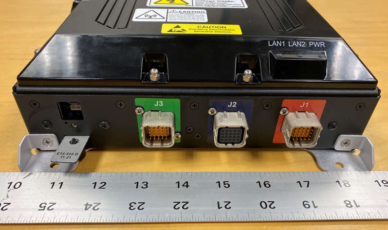
804 S. Northpoint Blvd. | Waukegan, IL 60085 astronics.com +1.847.244.4500 700-00016-000 CabinAXe™ User’s Manual THIS DOCUMENT IS THE SOLE PROPERTY OF ASTRONICS CONNECTIVITY SYSTEMS & CERTIFICATION (“ASTRONICS CSC”) AND SHALL NOT BE REPRODUCED, COPIED OR ISSUED AS THE BASIS OF MAINTENANCE OR SALE OF APPARATUS WIHTOUT PERMISSION OF ASTRONICS CSC. Astronics CSC Inflight Entertainment and Connectivity Systems Page | 2 Revision Date July. 26, 2022 || Document Number UM-700-00016-000 || Rev A astronics.com Copyright © Copyright 2022 Astronics CSC. Astronics CSC trademarks include , Cabin Ace-2™, Cabin Ace™, Cabin Pinnacle™, Cabin Vista™, Edge ™, CabinAXe™, All rights reserved. All other trademarks are the property of their respective owners. Open Source Code This product includes code licensed under GNU General Public License, and/or certain other open source licenses. FCC COMPLIANCE STATEMENT CAUTION: Changes or modifications not expressly approved could void your authority to use this equipment. This device complies with Part 15 of the FCC Rules. Operation to the following two conditions: (1) This device may not cause harmful interference, and (2) this device must accept any interference received, including interference that may cause undesired operation. INDUSTRY CANADA COMPLIANCE STATEMENT This device complies with Industry Canada licence-exempt RSS standard(s). Operation is subject to the following two conditions: (1) this device may not cause interference, and (2) this device must accept any interference, including interference that may cause undesired operation of the device. Le présent appareil est conforme aux CNR d'Industrie Canada applicables aux appareils radio exempts de licence. L'exploitation est autorisée aux deux conditions suivantes : (1) l'appareil ne doit pas produire de brouillage, et (2) l'utilisateur de l'appareil doit accepter tout brouillage radioélectrique subi, même si le brouillage est susceptible d'en compromettre le fonctionnement. Page | 3 Revision Date July. 26, 2022 || Document Number UM-700-00016-000 || Rev A astronics.com 1 TABLE OF CONTENTS 1 User Information .................................................................................................................................... 5 1.1 Support Documentation ................................................................................................................ 5 1.2 Industry Standards ........................................................................................................................ 6 1.3 Warranty ........................................................................................................................................ 6 1.4 Exclusion of Liability Notice ........................................................................................................... 6 2 Important Safety Instructions ................................................................................................................ 7 3 Introduction ............................................................................................................................................ 8 3.1 Product Description ....................................................................................................................... 8 3.2 Hardware Architecture .................................................................................................................. 8 3.3 Key Hardware Components .......................................................................................................... 9 3.4 Orderable Part Numbers ............................................................................................................. 11 4 Starting Up .......................................................................................................................................... 12 4.1 Power Up ..................................................................................................................................... 12 4.2 Startup process ........................................................................................................................... 12 4.3 IP Strapping Table ...................................................................................................................... 17 4.4 Connecting using the Console Port ............................................................................................ 18 4.5 Connecting using Web-based GUI ............................................................................................. 19 4.6 Virtual Controller Architecture ..................................................................................................... 22 4.7 WLAN Setup................................................................................................................................ 24 5 Physical I/O ......................................................................................................................................... 31 5.1 Connections and Cabling ............................................................................................................ 31 5.2 Maintenance Connectors ............................................................................................................ 34 5.3 Status Indicators ......................................................................................................................... 34 6 Performance Data ............................................................................................................................... 35 6.1 Radio Characteristics .................................................................................................................. 35 6.2 RF Performance Table ................................................................................................................ 36 7 Technical Data ...................................................................................................…

Text truncated - open the document above for the full version.

Users Manual

Page | 19 Revision Date July. 26, 2022 || Document Number UM-700-00016-000 || Rev A astronics.com 4.5 Connecting using Web-based GUI You can connect to the web-based GUI by entering the Aruba AP’s IP address in a web browser, and entering the Username and Password when prompted as shown below in Figure 6. If the IP strapping pins have not been set, you can use the show ip interface CLI command to display the IP address that was assigned by your DHCP server Note: The following subsections refer to the [Aruba] IAP, or AP which shall be used interchangeably with the CWAP. The sections are summarized from Aruba Instant documentation and training materials. For additional information refer to the Aruba Instant User Guide. Figure 6: Aruba Instant GUI Login Prompt You may see a Certificate Error message. This is because the certificates issued to the AP do not match the IP address used to connect to the GUI. It is recommended that you add a certificate issued by your network, to ensure secure administrative communication. Page | 20 Revision Date July. 26, 2022 || Document Number UM-700-00016-000 || Rev A astronics.com The main GUI page is broken up into the following sections. These sections are identified below Figure 7. Note: The left-most panel on the GUI provides access to Dashboard, Configuration, Maintenance, and Support areas. 1. Overview—This section displays the number of configured networks, access points, and clients. 2. Info—This section displays information about the access point name, country code, virtual controller IP address, management, conductor Instant AP IP address, IPv6 address, uplink type, and uplink status. 3. Clients—The Clients graph displays the number of clients that were associated with the virtual controller in the last 15 minutes. 4. Throughput—The Throughput Graph shows the throughput of the selected client for the last 15 minutes. a. Out – Throughput for the outgoing traffic is displayed in blue. b. In - Throughput for the incoming traffic is displayed in orange. To see an enlarged view, click the graph. To see the exact throughput at a particular time, move the cursor over the graph line. 5. RF Dashboard—This section displays the Instant APs that exceed the utilization, noise, or error threshold. It also shows the clients with low speed or signal strength in the network and the RF information for the Instant AP to which the client is connected. Figure 7: The Sections of the Aruba Instant Main GUI Page Page | 21 Revision Date July. 26, 2022 || Document Number UM-700-00016-000 || Rev A astronics.com 4.5.1 System Username and Password The default username for the Aruba is admin. The default password will be one of the following, admin, cabinaxe, or the Aruba serial number. It is recommended that these be changed. The system username and password can be changed from the Admin selection in the GUI. Using the options on the GUI left-most panel, the path to set this is: Configuration > System, then select Admin from the GUI as shown in Figure 8. Figure 8: System Username and Password Dialog Box. Page | 22 Revision Date July. 26, 2022 || Document Number UM-700-00016-000 || Rev A astronics.com 4.6 Virtual Controller Architecture The Aruba IAP uses a Virtual Controller architecture for ease of deployment and centralized wireless network management. An Instant AP cluster consists of member Instant APs and a conductor Instant AP in the same VLAN, as they communicate with broadcast messages. A virtual controller is a combination of the whole cluster, as the member Instant APs and conductor Instant AP coordinate to provide a controllerless Instant solution. In an Instant deployment scenario, the first Instant AP that comes up becomes the conductor Instant AP. All other Instant APs joining the cluster after that Instant AP, become the member Instant APs. In an Instant deployment scenario, only the first Instant AP or the conductor Instant AP needs to be configured. The other Instant APs download configurations from the first Instant AP that is configured. The Instant solution constantly monitors the network to determine the Instant AP that must function as a conductor Instant AP at a given time. The conductor Instant AP may change as necessary from one Instant AP to another without impacting network performance. Each Instant AP model has a minimum required software version. You can set the name of the virtual controller along with other configuration parameters, from the General tab of the System dialog box, as show in Figure 9 below. Figure 9: The Virtual Controller General Setup screen. Page | 23 Revision Date July. 26, 2022 || Document Number UM-700-00016-000 || Rev A astronics.com 4.6.1 IAP Configuration On the Configuration GUI page you can select one of the IAPs and edit the configuration. You should give each of your IAPs a relevant name for easy identification. You can also select which IAP will be the preferred master. Whichever IAP is configured as the preferred master will also become the virtual controller. Access is via the left-panel: Configuration > Access Points (Select the Access Point, and use the edit “pencil”). See Figures 10 & 11. Figure 10: Select / Edit the Access Point screen. Figure 11: The Edit Access Point screen. Page | 24 Revision Date July. 26, 2022 || Document Number UM-700-00016-000 || Rev A astronics.com 4.7 WLAN Setup There are four steps to creating an SSID: 1. Configure WLAN Settings. Select the type of SSID you want to create. a. Employee Network: This network type is used by the employees in an organization and it supports passphrase-based or 802.1X-based authentication methods. b. Voice Network: This network type provides voice traffic prioritization, and allows you to configure a network profile for devices that only provide voice services. c. Guest Network: Provides captive portal or passphrase-based authentication methods for non-employee users. 2. Configure VLAN Settings for a WLAN SSID Profile. 3. Configure Security Settings for a …

Text truncated - open the document above for the full version.

Users Manual

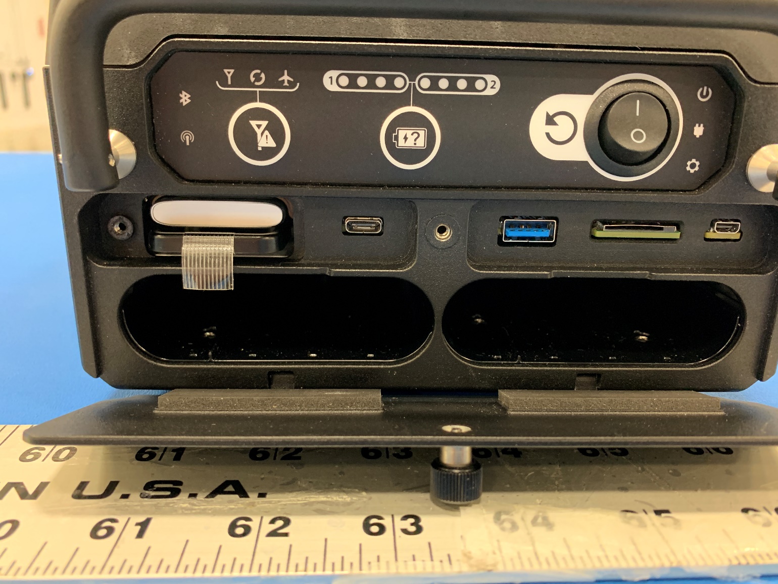
Page | 28 Revision Date July. 26, 2022 || Document Number UM-700-00016-000 || Rev A astronics.com Figure 16: Personal Security level options Finally, selecting the Enterprise level allows you to configure an external RADIUS authentication server, as shown below in Figure 17. Page | 29 Revision Date July. 26, 2022 || Document Number UM-700-00016-000 || Rev A astronics.com Figure 17: Enterprise Security level options Step 4 The Access tab is where you configure the firewall rules and user rights. As shown in Figure 18, the Access tab allows you to create Network-Based rules and Role-Based rules. You also have the option to leave the SSID Unrestricted. Page | 30 Revision Date July. 26, 2022 || Document Number UM-700-00016-000 || Rev A astronics.com Figure 18: Access Rules options Figure 19 shows an example of creating a rule that denies all DNS traffic except to the DNS server with the IP address of 192.168.10.1. Figure 19: Configuring Firewall Rules Refer to the Aruba Instant Users Guide for additional information on the Virtual Controller GUI. Page | 31 Revision Date July. 26, 2022 || Document Number UM-700-00016-000 || Rev A astronics.com 5 Physical I/O 5.1 Connections and Cabling Table 6 lists the CWAP’s external connector interfaces (per ARINC 628). Table 6: CWAP External Connector Interfaces Ref Des. Shell Insert Mating Shell Mating Insert J1 EN4165M01AA EN4165A20-22-1NA EN4165M61AA EN4165A20-22-1NB J2 EN4165M01AB EN4165A20-22-1NB EN4165M61AB EN4165A20-22-1NA J3 EN4165M01AC EN4165A20-22-1NA EN4165M61AC EN4165A20-22-1NB 5.1.1 Connector Definition J1 The J1 connector carries the input power, connects the CWAP to the upstream server/network, and carries both the Power Enable and RF Enable discrete signals to the unit. Figure 20 shows connector layout and pin definitions for the CWAP’s J1 external aircraft connection. Figure 20: J1 (Pins) Connector Layout and Pin Definitions Page | 32 Revision Date July. 26, 2022 || Document Number UM-700-00016-000 || Rev A astronics.com 5.1.2 Connector Definition J2 The J2 connector passes power, Ethernet and both the Power Enable, and RF Enable discrete signals to the next downstream CWAP when the units are in a Daisy Chain configuration. Figure 21 shows connector layout and pin definitions for the CWAP’s J2 external aircraft connection. Figure 21: J2 (Socket) Connector Layout and Pin Definitions Page | 33 Revision Date July. 26, 2022 || Document Number UM-700-00016-000 || Rev A astronics.com 5.1.3 Connector Definition J3 The J3 carries the discrete IP strapping signals from the aircraft to the CWAP. Figure 22 shows connector layout and pin definitions for the CWAP’s J3 external aircraft connection. Please see Table 5 for IP Address information. Figure 22: J3 (Socket) Connector Layout and Pin Definitions Page | 34 Revision Date July. 26, 2022 || Document Number UM-700-00016-000 || Rev A astronics.com 5.2 Maintenance Connectors Two maintenance connectors are located on the front of the unit behind the maintenance door. • The J10 connector is a female micro USB that provides a serial interface to both the SIB and the AP. • A four pin SIB programming header is located below the J10 connector. This programming header provides an interface for programming the SIB bootloader. Reset button The reset button is located behind the maintenance door. Holding the reset button for 5 seconds, until the power LED rapidly blinks, will factory reset the Aruba AP. 5.3 Status Indicators The CWAP has four (4) AP status LEDs, and three (3) CWAP indicators that are visible on the top (radome) of the CWAP and are to be used to indicate the AP status and activity. The meanings of these indicators are defined in Table 7 below. Table 7: AP LED Operation Indicator Color/State Meaning AP Status LED OFF AP Powered OFF. Green - Solid AP ready, fully functional, no network restrictions. Green - Blinking note 1 AP booting, not ready. Green - Flashing Off note 2 Device ready, fully functional, either uplink negotiated in sub-optimal speed (<1Gbps). Green - Flashing On note 3 Device in deep-sleep mode. Amber - Solid Device ready, restricted power mode, no network restrictions. Amber - Flashing Off Device ready, restricted power mode, uplink negotiated in sub-optimal speed. Red - Solid System error condition. AP Radio Status (One each for 2.4GHz, 5GHz, 6GHz radios) OFF Device is powered OFF, or radios disabled. Green - Solid Radios enabled in access mode. Green - Flashing Off One radio enabled in uplink or mesh mode. Amber - Solid Radios enabled in monitor mode or spectrum analysis mode. CWAP Power Green - Solid Red - Solid AC is present – No fault detected. AC power present – Fault detected. Ethernet Link (LAN 1, LAN 2) Green - Blinking Indicates link activity for LAN 1 (J1 connector) and LAN 2 (J2 connector). Notes: 1. Blinking: one second on, one second off, 2-seconds cycle 2. Flashing off: mostly on, fraction of a second off, 2-second cycle 3. Flashing on: mostly off, fraction of a second on, 2-seconds cycle Page | 35 Revision Date July. 26, 2022 || Document Number UM-700-00016-000 || Rev A astronics.com 6 Performance Data 6.1 Radio Characteristics Table 8: Radio Characteristics Feature Description Supported Frequency Bands country-specific restrictions apply -2.400 to 2.4835 GHz ISM -5.150 to 5.250 GHz U-NII-1 -5.250 to 5.350 GHz U-NII-2 -5.470 to 5.725 GHz U-NII-2E -5.725 to 5.850 GHz U-NII-3/ISM * -5.850 to 5.895 GHz U-NII-4 -5.925 to 6.425 GHz U-NII-5 -6.425 to 6.525 GHz U-NII-6 -6.525 to 6.875 GHz U-NII-7 -6.875 to 7.125 GHz U-NII-8 Operating Channels Dependent on configured regulatory domain. Supported radio technologies -802.11b: Direct-sequence spread-spectrum (DSSS) -802.11a/g/n/ac: Orthogonal frequency-division multiplexing (OFDM) -802.11ax: Orthogonal frequency-division multiple access (OFDMA) Supported Modulation Types -802.11b: BPSK, QPSK, CCK -802.11a/g/n/ac: BPSK, QPSK, 16-QAM, 64-QAM,256-QAM -802.11ax: BPSK, QPSK, 16-QAM, 64-QAM,256-QAM, 1024-QAM, 4096-QAM -802.11n hig…

Text truncated - open the document above for the full version.

Users Manual

804 S. Northpoint Blvd. | Waukegan, IL 60085 astronics.com +1.847.244.4500 700-00016-000 CabinAXe™ User’s Manual (IMAGE FOR REFERENCE ONLY) THIS DOCUMENT IS THE SOLE PROPERTY OF ASTRONICS CONNECTIVITY SYSTEMS & CERTIFICATION (“ASTRONICS CSC”) AND SHALL NOT BE REPRODUCED, COPIED OR ISSUED AS THE BASIS OF MAINTENANCE OR SALE OF APPARATUS WIHTOUT PERMISSION OF ASTRONICS CSC. Astronics CSC Inflight Entertainment and Connectivity Systems Page | 2 Revision Date: January 18, 2023 || Document Number UM-700-00016-000 || Rev B astronics.com Copyright © Copyright 2022 Astronics CSC. Astronics CSC trademarks include , Cabin Ace-2™, Cabin Ace™, Cabin Pinnacle™, Cabin Vista™, Edge ™, CabinAXe™, All rights reserved. All other trademarks are the property of their respective owners. Open Source Code This product includes code licensed under GNU General Public License, and/or certain other open source licenses. FCC COMPLIANCE STATEMENT CAUTION: Changes or modifications not expressly approved could void your authority to use this equipment. This device complies with Part 15 of the FCC Rules. Operation to the following two conditions: (1) This device may not cause harmful interference, and (2) this device must accept any interference received, including interference that may cause undesired operation. The operation of this device is prohibited on oil platforms, cars, trains, boats, and aircraft, except that operation of this device is permitted in large aircraft while flying above 10,000 feet. Operation in the 5.9725-7.125GHz band is prohibited for control of or communication with unmanned aircraft systems. INDUSTRY CANADA COMPLIANCE STATEMENT This device complies with Industry Canada licence-exempt RSS standard(s). Operation is subject to the following two conditions: (1) this device may not cause interference, and (2) this device must accept any interference, including interference that may cause undesired operation of the device. Le présent appareil est conforme aux CNR d'Industrie Canada applicables aux appareils radio exempts de licence. L'exploitation est autorisée aux deux conditions suivantes : (1) l'appareil ne doit pas produire de brouillage, et (2) l'utilisateur de l'appareil doit accepter tout brouillage radioélectrique subi, même si le brouillage est susceptible d'en compromettre le fonctionnement. EUROPEAN UNION COMPLIANCE STATEMENT Hereby, Astronics CSC, declares that this Cabin Wireless Access Point is in compliance with the essential requirements and other relevant provisions of Directive 2014/53/EU. The full text of the EU Declaration of Conformity (DoC) is available at the following internet address: https://eur-lex.europa.eu/legal- content/EN/TXT/PDF/?uri=CELEX:32014L0053&from=EN. Page | 3 Revision Date: January 18, 2023 || Document Number UM-700-00016-000 || Rev B astronics.com 1 TABLE OF CONTENTS 1 User Information .................................................................................................................................... 5 1.1 Support Documentation ................................................................................................................ 5 1.2 Industry Standards ........................................................................................................................ 6 1.3 Warranty ........................................................................................................................................ 6 1.4 Exclusion of Liability Notice ........................................................................................................... 6 2 Important Safety Instructions ................................................................................................................ 7 2.1 Safety and Precautions ................................................................................................................. 7 2.2 Regulatory ..................................................................................................................................... 8 3 Introduction .......................................................................................................................................... 10 3.1 Product Description ..................................................................................................................... 10 3.2 Hardware Architecture ................................................................................................................ 10 3.3 Key Hardware Components ........................................................................................................ 11 3.4 Orderable Part Numbers ............................................................................................................. 13 4 Starting Up .......................................................................................................................................... 14 4.1 Power Up ..................................................................................................................................... 14 4.2 Startup process ........................................................................................................................... 14 4.3 IP Strapping Table ...................................................................................................................... 19 4.4 Connecting using the Console Port ............................................................................................ 20 4.5 Connecting using Web-based GUI ............................................................................................. 21 4.6 Virtual Controller Architecture ..................................................................................................... 24 4.7 WLAN Setup................................................................................................................................ 26 5 Physical I/O ......................................................................................…

Text truncated - open the document above for the full version.

Attestation Statements

October 30, 2017 To: Certification and Conformity Assessment Bodies Subject: Aruba Networks Acquisition Hereby Hewlett-Packard Enterprise Company, incorporated under the laws of the State of Delaware, USA, and a manufacturer of IT and Telecommunication products, with the company registration No. 5699265, registration address: 3000 Hanover Street, Palo Alto, CA 94304-1185 USA (“HPE”), represented by Mr. Rishi Varma, Senior Vice President and Deputy General Counsel, informs that on May 19, 2015 “Aruba Networks Inc.” (“Aruba”) was acquired by HPE. Aruba is now a wholly-owned subsidiary of HPE. Products manufactured by or on behalf of Aruba are now part of HPE. All technical documents, issued for or on behalf of Aruba, are the property of HPE. Sincerely Brent A. Ford Robert Hastings Regulatory Engineering Manager Regulatory Compliance Manager HPE Networking Business Aruba, a Hewlett Packard Enterprise company

Attestation Statements

804 S. Northpoint Blvd | Waukegan, IL 60085astronics.com +1.847.244.4500 TO: Federal Communication Commission Equipment Authorization Division Application Processing Branch 7435 Oakland Mills Rd Columbia, MD 21046 Date: 02/20/2023 Pursuant to FCC 22-84 Report and Order and KDB 986446 D01 Covered Equipment v01, the Commission adopted new FCC requirements to protect the nation’s networks and supply chains from equipment that poses an unacceptable risk to national security or the safety of U.S. persons. Specifically, the Commission adopted rules that prohibit equipment authorization for “covered” telecommunications equipment and video surveillance equipment produced by entities identified on the Commission’s Covered List. Certification designating a U.S. agent for service of process. As required by section 2.911(d)(7), the applicant must designate a contact located in the United States for purposes of acting as the applicant’s agent for service of process, regardless of whether the applicant is a domestic or foreign entity. An applicant located in the United States may designate itself as the agent for service of process. 1. Be signed by both the applicant and the designated agent for service of process if the agent is different from the applicant. 2. Astronics CSC (“the applicant”) consent to accept the service of process. Astronics CSC acknowledges to maintain an agent for no less than one year after the grantee has terminated all marketing and importation or the conclusion of any Commission-related proceeding involving the equipment. Regards, Signature: Date: 02/20/2023 Signed by (printed name): Jim Costello

Attestation Statements

804 S. Northpoint Blvd | Waukegan, IL 60085 astronics.com +1.847.244.4500 TO: Federal Communication Commission Equipment Authorization Division Application Processing Branch 7435 Oakland Mills Rd Columbia, MD 21046 Date: 03/13/2023 Pursuant to FCC 22-84 Report and Order and KDB 986446 D01 Covered Equipment v01, the Commission adopted new FCC requirements to protect the nation’s networks and supply chains from equipment that poses an unacceptable risk to national security or the safety of U.S. persons. Specifically, the Commission adopted rules that prohibit equipment authorization for “covered” telecommunications equipment and video surveillance equipment produced by entities identified on the Commission’s Covered List. Certifications concerning “covered” equipment. Section 2.911(d)(5)(i)-(ii). Astronics CSC (“the applicant”) certifies that as of the date of the filing of the application, the applicant is not identified on the covered list as an entity producing covered equipment. Thank you. Regards, Signature: Date: 03/13/2023 Signed by (printed name): Jim Costello

Cover Letter(s)

Federal Communications Commission Authorization and Evaluation Division 7435 Oakland Mills Road Columbia, MD 21046 To Whom It May Concern: Authorization Letter Aruba a Hewlett Packard Enterprise Company hereby authorize Astronics CSC to file a change in ID for the following Aruba Access Point: APIN0635 (FCC ID: Q9DAPIN0635) Grant Dates: Date of Grant: 07/29/2021 [Q9DAPIN0635] 15C, 15E, 15E DFS & 15E 6GHz Sincerely, ____________________________ Signature Name/Position: Phillip Carranco Manager Regulatory Compliance Email: [email protected]

Cover Letter(s)

804 S. Northpoint Blvd. | Waukegan, IL 60085 astronics.com +1.847.244.4500 Date: 09/08/2022 TO: Federal Communication Commission 7435 Oakland Mills Rd Columbia, MD 21046 Exhibit Subject: Request for Re-use of Reference Data We, Astronics CSC submit this formal request to the FCC Authorization and Evaluation Division for an expedited review of a new authorization application. The purpose of this exhibit is this application includes test data from another FCC ID for the reference of EMC/Radio Parameters. This exhibit follows guidance in FCC KDB 484596 D01 Referencing Test Data v01 and it identifies the suitability of using existing reference EMC/Radio Parameter data for a new application. 1- Introduction: Astronics CSC has created a new product called the CabinAXe Cabin Wireless Access Point (CWAP). This new product incorporates an existing certified WiFi Access Point (manufactured by Aruba Networks) into the new CabinAXe product housing. The Astronics integration removes the complete electronics assembly from the Aruba certified access point enclosure and incorporates the Aruba electronics/PCB without making changes to the electronics/PCB into the new CabinAXe IFE product housing. The electronics/PCB from the certified Aruba Access Point are certified as noted: Date of Grant: 07/29/2021 The Aruba WiFi Access Point is certified as FCC ID: Q9DAPIN0635. Equipment Class: DTS, UNII-TX Rule Parts: 15.247, 15.407 Frequency Range(MHz) 2400-2484 Frequency Range(MHz) 5150-5250; 5250-5350; 5470-5725; 5725-5850 Frequency Range(MHz) 5850-5895; 5925-6425; 6425-6525; 6525-6875; 6875-7.125 The Aruba electronics/PCB are integrated into the CabinAXe system with a new certification as noted: Date of Grant: New Grant The new Astronics CabinAXe system is being certified as FCC ID: 2AL4H-70000016. Equipmen…

Text truncated - open the document above for the full version.

Contact Information

Applicant

James Costello(Chief Technology Officer)
[email protected]847-244-4500Fax: 847-244-4525

Technical Contact

Astronics CSCJames Costello
[email protected]8472444500

804 S Northpoint Blvd · Waukegan · United States

Non-Technical Contact

Astronics CSCJames Costello
[email protected]8472444500

Test Firm

Elite Electronic Engineering Inc.Kevin Halpin
[email protected]630-495-9770Fax: 630-495-9785

Technical Specifications

#Rule PartsFrequency RangePower Output
315C2.41 GHz - 2.46 GHz156.00 mW
Software Defined Radio
Yes
Confidentiality
Long Term
Grant Notes
Software Defined Radio Device. Power listed is peak conducted power for BT and Zigbee and maximum combined output average for WIFI 2.4GHz. Device operates with specific antennas in 2x2 MIMO configurations as described in this filing. Professional or OEM installation required. The antenna(s) used for this transmitter must be installed to provide a separation distance of at least 20 cm from all persons and must not transmit simultaneously with any other antenna or transmitter. Users and installers must be provided with antenna installation instructions and transmitter operating conditions for satisfying RF exposure compliance. This device has 20 MHz, and 40 MHz, bandwidth modes.
Other Applications from Astronics CSC

Access Point - FCC ID 2AL4H-E71314 - Astronics CSC
2AL4H-E71314

Access Point

Jun 07, 2020

Equipment Class

DTS - Digital Transmission System