2ALGLM2000Cassia Bluetooth Gateway
Cassia Networks Inc.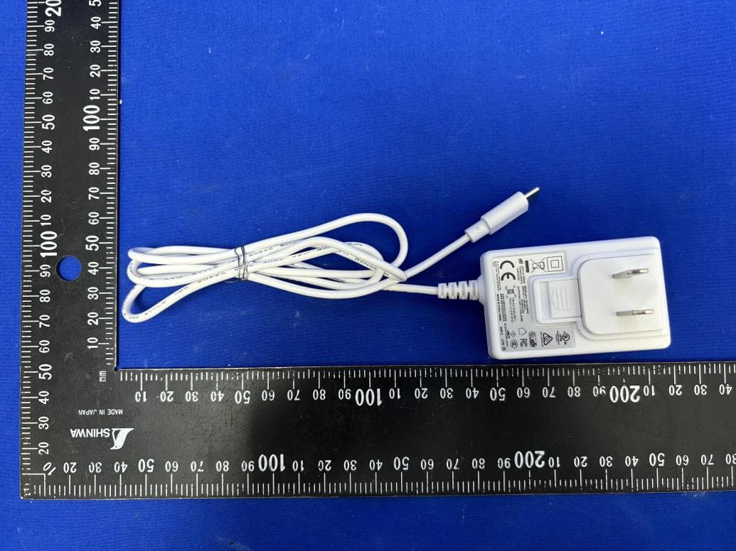
Click to zoom
Application Details
- Equipment Class
- DTS - Digital Transmission System
- Date of Grant
- Nov 28, 2024
- Application Purpose
- Original Equipment
- Date of Application
- Nov 25, 2024
- Equipment Note
- Cassia Bluetooth Gateway
- Frequency Range
- 2402.00000000 - 2480.00000000
- Company
- Cassia Networks Inc.
- Country
- United States
Documents & Files
Document Text
Text extracted from the exhibit documents filed with the FCC. Open a document above to read the original.
Users Manual
印刷说明 �.此说明采用印刷方式加工 �.纸张采用���g的哑粉纸 �.说明书为��折页,双面印刷 �.展开尺寸为���*��mm,折叠后尺寸为��*��mm �.印刷颜色为黑白 此页不印刷 Copyright © 2024 Cassia Networks, Inc. Cassia Networks and the Cassia Networks logo are trademarks of Cassia Networks, Inc. QUICK START GUIDE CASSIA M2000 BLUETOOTH GATEWAY I. INCLUDED IN PACKAGE 1 3 2. USB Power Plugs3. Mounting Bracket1. M2000 Gateway 4. Quick Start Guide5. USB Power Adapter 2 45 -1- II. PORTS AND LED Reset button System & Wi-Fi LED light 4G LED light Bluetooth LED light USB-C power input Micro SIM card socket RESET SYS4GBLE -2- LED SYS 4G BLE StatusDescription Off Solid on Fast flashing Slow flashing Slow flashing (200ms ON/1800ms OFF) Slow flashing (1800ms ON/200ms OFF) Fast flashing Off Solid on Flashing Power off The system is operating normally. Wi-Fi connection is NOT established The system is starting The system is operating normally. Wi-Fi connection is established Network searching Idle Data transfer is ongoing The Bluetooth chip didn’t start Bluetooth is operating normally Flash twice when the Bluetooth connection is established -3- III. MOUNTING & INSTALLATION Step 1: Open the silicone plug of the SIM card socket, and then insert the Micro SIM card referring to the diagram below. Make sure that the beveled corner of the SIM card is correct. If using Wi-Fi backhaul, please ignore this step Step 2: Connect the USB-C power supply to the M2000 SIM card bevel angel -4- Notes: 1When inserting the SIM card, push it in until it is held in place by the slot. 2When removing the SIM card, push it in until it pops out. Step 3: Stick the mounting bracket to the wall Step 4: Slide M2000 down on the mounting bracket -5- IV. SETUP BLUETOOTH GATEWAY V. PRODUCT INTERFACE Connect to the M2000's Wi-Fi hotspot using a computer or mobile phone. The hotspot's name is cassia-xxxxxx. The password of the hotspot is the same as the name. xxxxxx is the last six characters of the M2000's MAC address. For instance, if the MAC address of an M2000 is CC:1B:E0:E3:0D:8C, both the Wi-Fi hotspot name and password are cassia-E30D8C After connecting to the M2000's Wi-Fi hotspot, open a web browser and enter 192.168.40.1 into the address bar. The default username and password are admin and admin. Fill in the fields for settings like AC Server Address, Wi-Fi, and Cellular Modem. Power input: USB-C, DC 5V 2A Bluetooth Low Energy: 4.0/4.1/4.2/5.0 Wi-Fi: 802.11 b/g/n, 2.4GHz. Please only use the Wi-Fi AP that supports 2.4GHz Cellular: CAT-M1 and NB-IoT GPS: Active GPS with an internal GPS antenna Reset button: Restore to factory settings Record the last six digits of the MAC address on the back of the M2000. 2. 1. 3. 4. -6- -7- VI. TEMPERATURE MEASUREMENT Range: -30°C to +70°C (-22°F to +158°F) Accuracy: ±1°C (1.8°F) VII. HUMIDITY MEASUREMENT Range: 0 to 99% RH Accuracy: ±5% RH (at 25°C / 77°F) VIII. ENVIRONMENTAL Operating temperature: -30°C to +70°C (-22°F to +158°F) Humidity: 0% to 90% non-condensing Storage and transportation temperature: -50°C to +70°C (-58°F to +158°F) IP rating: IP30 (>2.5mm solid protection, no liquid protection) For additional assistance, please email: [email protected] IX. FEDERAL COMMUNICATIONS COMMISSION (FCC) INTERFERENCE STATEMENT This equipment has been tested and found to comply with the limits for a Class B digital device, pursuant to part 15 of the FCC Rules. These limits are designed to provide reasonable protection against harmful interference in a residential installation. This equipment generates, uses and can radiate radio frequency energy and, if not installed and used in accordance with the instructions, may cause harmful interference to radio communications. However, there is no guarantee that interference will not occur in a particular installation. If this equipment does cause harmful interference to radio or television reception, which can be determined by turning the equipment off and on, the user is encouraged to try to correct the interference by one or more of the following measures: — Reorient or relocate the receiving antenna. — Increase the separation between the equipment and receiver. — Connect the equipment into an outlet on a circuit different from that to which the receiver is connected. — Consult the dealer or an experienced radio/TV technician for help. -8- NOTE: Any changes or modifications not expressly approved by the party responsible for compliance could void the user's authority to operate the equipment. For additional information, please go to: https://www.cassianetworks.com X. RF EXPOSURE WARNING This equipment must be installed and operated in accordance with provided instructions and the antenna(s) used for this transmitter must be installed to provide a separation distance of at least 20 cm from all persons and must not be co-located or operating in conjunction with any other antenna or transmitter. End-users and installers must be provided with antenna installation instructions and transmitter operating conditions for satisfying RF exposure compliance. XI. EU REGULATORY CONFORMANCE -9- Cassia Networks Inc., hereby declares that Cassia M2000 Series Bluetooth Gateway is in compliance with directives listed below: EMC Directive 2014/30/EU Low Voltage Directive 2014/35/EU RED Directive 2014/53/EU REACH European Regulation (EC) No 1907/2006 RoHS Directive 2011/65/EU & 2015/863/EU WEEE Directive 2012/19/EU A Declaration of Conformity for these directives is available for viewing at https://www.cassianetworks.com Copyright © 2024 Cassia Networks, Inc. Cassia Networks et le logo Cassia Networks sont des marques déposées de Cassia Networks, Inc. CASSIA M2000 PASSERELLE BLUETOOTH GUIDE DE DÉMARRAGE RAPIDE I. INCLUS DANS L'EMBALLAGE 1 3 2. Prises d'alimentation USB3. Support de montage1. Passerelle M2000 4. Guide de démarrage rapide5. Adaptateur d'alimentation USB 2 45 -1- II. PORTS ET LED Bouton de réinitialisation Témoin lumineux système & Wi-Fi Témoin lumineux 4G Témoin lumineux Bluetooth Entrée d'alimentation USB-C Port de carte SIM …
Text truncated - open the document above for the full version.
Attestation Statements
Rev9/6/2024 CassiaNetworksInc. FederalCommunicationsCommission AuthorizationandEvaluationDivision 7435OaklandMillsRoad Columbia,MD21046 USA Date:20-11-2024 Ref:AttestationStatementsPart2.911(d)(7)Filing GranteeCode:2ALGL CassiaNetworksInc.certifiesthat,asofthedateofthefilingoftheapplication,wedesignateourselves astheU.S.agentforserviceofprocess. DesignatedU.S.AgentInformation: FRN:0026341537 Name:CassiaNetworksInc. Address:97E.BrokawRoad,Suite130,SanJose,CA95112 ContactPerson:MingyuanHuang Tel.:1-4084316870 Email:[email protected] Sincerely, CassiaNetworksInc. MingyuanHuang Applicant signature:
External Photos
Report No.: 2408RSU011-UE 1 of 11 EUT External Photograph (1) EUT Photo (2) EUT Photo Report No.: 2408RSU011-UE 2 of 11 (3) EUT Photo (4) EUT Photo Report No.: 2408RSU011-UE 3 of 11 (5) EUT Photo (6) EUT Photo Report No.: 2408RSU011-UE 4 of 11 (7) EUT Photo (8) EUT Photo Report No.: 2408RSU011-UE 5 of 11 (9) EUT Photo
ID Label/Location Info
23.00 90.00 90.00 12.5 20240430 M2000 marking content should be centered horizontally Enter K3 timePhase DesignStandardization Approved Date Wang Furong Review Process Coating Product Model Component Name First AngleProjection PageRevision QuantityWeightScale M2000 BOTTOM COVER Drawing Number ZHEJIANG SUNPARL INFORMATION TECHNLOGY CO., LTD Part Number
Internal Photos
Report No.: 2408RSU011-UE 6 of 11 EUT Internal Photograph (10) EUT Photo (11) EUT Photo Report No.: 2408RSU011-UE 7 of 11 (12) EUT Photo (13) EUT Photo Report No.: 2408RSU011-UE 8 of 11 (14) EUT Photo (15) EUT Photo Report No.: 2408RSU011-UE 9 of 11 (16) EUT Photo (17) EUT Photo Report No.: 2408RSU011-UE 10 of 11 (18) EUT Photo (19) EUT Photo Report No.: 2408RSU011-UE 11 of 11 (20) EUT Photo (21) EUT Photo
RF Exposure Info
MRT Technology (Suzhou) Co., Ltd Report No.: 2408RSU011-U3 Phone: +86-512-66308358 Report Version: V01 Web: www.mrt-cert.com Issue Date: 2024-11-21 Template Version:0.1 1 of 12 RF Exposure Evaluation Declaration FCC ID: 2ALGLM2000 Applicant: CASSIA NETWORKS INC. Product: Cassia Bluetooth Gateway Model No.: M2000 Brand Name: CASSIA FCC Rule Part(s): FCC Part 2.1091 Result: Complies Evaluation Date: 2024-11-05 Reviewed By: Denise Zhou Approved By: Robin Wu The test results relate only to the samples tested. The test results shown in the test report are traceable to the national/international standards through the calibration of the equipment and evaluated measurement uncertainty herein. The test report shall not be reproduced except in full without the written approval of MRT Technology (Suzhou) Co., Ltd. Report No.: 2408RSU011-U3 2 of 12 Revision History Report No. Version Description Issue Date Note 2408RSU011-U3 V01 Initial Report 2024-11-21 Valid Report No.: 2408RSU011-U3 3 of 12 CONTENTS Description Page 1. General Information ............................................................................................................................... 4 1.1. Applicant ........................................................................................................................................4 1.2. Manufacturer .................................................................................................................................4 1.3. Testing Facility ...............................................................................................................................4 1.4. Product Information .......................................................................................................................5 1.5. Antenna Details .............................................................................................................................6 1.6. Device Classification .....................................................................................................................6 1.7. Applied Standards .........................................................................................................................6 2. RF Exposure Evaluation ........................................................................................................................ 7 2.1. Limits .............................................................................................................................................7 2.2. MPE Exemptions ...........................................................................................................................8 2.3. Calculated Result ........................................................................................................................ 11 Report No.: 2408RSU011-U3 4 of 12 1. General Information 1.1. Applicant CASSIA NETWORKS INC. 97 E. Brokaw Road, Suite 130, San Jose, CA 95112 1.2. Manufacturer CASSIA NETWORKS INC. 97 E. Brokaw Road, Suite 130, San Jose, CA 95112 1.3. Testing Facility Test Site – MRT Suzhou Laboratory Laboratory Location (Suzhou - Wuzhong) D8 Building, No.2 Tian’edang Rd., Wuzhong Economic Development Zone, Suzhou, China Laboratory Location (Suzhou - SIP) 4b Building, Liando U Valley, No.200 Xingpu Rd., Shengpu Town, Suzhou Industrial Park, China Laboratory Location (Suzhou - Wujiang) Building 1, No.1 Xingdong Road, Wujiang, Suzhou, Jiangsu, People’s Republic of China Laboratory Accreditations A2LA: 3628.01 CNAS: L10551 FCC: CN1166 ISED: CN0001 VCCI: R-20025 G-20034 C-20020 T-20020 R-20141 G-20134 C-20103 T-20104 Test Site – MRT Shenzhen Laboratory Laboratory Location (Shenzhen) 1G, Building A, Junxiangda Building, Zhongshanyuan Road West, Nanshan District, Shenzhen, China Laboratory Accreditations A2LA: 3628.02 CNAS: L10551 FCC: CN1284 ISED: CN0105 Test Site – MRT Taiwan Laboratory Laboratory Location (Taiwan) No. 38, Fuxing 2nd Rd., Guishan Dist., Taoyuan City 333, Taiwan (R.O.C.) Laboratory Accreditations TAF: 3261 FCC: 291082, TW3261 ISED: TW3261 Report No.: 2408RSU011-U3 5 of 12 1.4. Product Information Product Name Cassia Bluetooth Gateway Model No. M2000 Wi-Fi Specification 802.11b/g/n Bluetooth Specification V5.1, BLE only 3GPP Specification LTE-M1: Band 2, 4, 5, 12, 13, 25, 26, 66, 85 NB-IoT: Band 2, 4, 5, 12, 13, 25, 66, 71, 85 GNSS Specification GPS, GLONASS, QZSS Antenna Information Refer to Section 1.5 Power Type By AC/DC Adapter Accessory Adapter Model No.: 6A-121WP05 Input Power: 100 - 240V ~ 50/60Hz, 0.6A Output Power: 5V ⎓ 2.0A, 10W Integrated Module Information Wi-Fi Module Module Name: Wi-Fi & Bluetooth Internet of Things Module Model No: ESP32-WROVER-E Brand Name: ESPRESSIF Cellular Module Module Name: LTE Cat M1 & Cat NB2 Module Model No: BG95-M6 Brand Name: Quectel Remark: The information of EUT was provided by the manufacturer, and the accuracy of the information shall be the responsibility of the manufacturer. Report No.: 2408RSU011-U3 6 of 12 1.5. Antenna Details Technology Frequency Range (MHz) Max Peak Gain (dBi) LTE-M1 Band 2 1850 ~ 1910 2.36 LTE-M1 Band 4 1710 ~ 1755 3.85 LTE-M1 Band 5 824 ~ 849 2.68 LTE-M1 Band 12 699 ~ 716 2.49 LTE-M1 Band 13 777 ~ 787 2.49 LTE-M1 Band 25 1850 ~ 1915 2.36 LTE-M1 Band 26 814 ~ 849 2.68 LTE-M1 Band 66 1710 ~ 1780 3.85 LTE-M1 Band 85 698 ~ 716 2.49 NB-IoT Band 2 1850 ~ 1910 2.36 NB-IoT Band 4 1710 ~ 1755 3.85 NB-IoT Band 5 824 ~ 849 2.68 NB-IoT Band 12 699 ~ 716 2.49 NB-IoT Band 13 777 ~ 787 2.49 NB-IoT Band 25 1850 ~ 1915 2.36 NB-IoT Band 66 1710 ~ 1780 3.85 NB-IoT Band 71 663 ~ 698 2.49 NB-IoT Band 85 698 ~ 716 2.49 2.4GHz Wi-Fi 2412 ~ 2472 3.40 BLE 2402 ~ 2480 1.00 Note: The antenna gain is from antenna data sheet provided by the manufacturer. 1.6. Device Classification According to the user manual, this device is classified as a Mobile Device. So, the RF exposure evaluation requirements of § 2.1091 for mobile device exposure conditions subject to MPE limits. 1.7. Applied Standards Ac…
Text truncated - open the document above for the full version.
Test Report
MRT Technology (Suzhou) Co., Ltd Report No.: 2408RSU011-U2 Phone: +86-512-66308358 Report Version: V01 Web: www.mrt-cert.com Issue Date: 2024-11-21 Template Version:1.7 1 of 70 RF MEASUREMENT REPORT FCC ID: 2ALGLM2000 Applicant: CASSIA NETWORKS INC. Product: Cassia Bluetooth Gateway Model No.: M2000 Brand Name: CASSIA FCC Classification: Digital Transmission System (DTS) FCC Rule Part(s): Part 15 Subpart C (Section 15.247) Result: Complies Received Date: 2024-08-07 Test Date: 2024-10-18 ~ 2024-10-24 Reviewed By: Denise Zhou Approved By: Robin Wu The test results relate only to the samples tested. This equipment has been shown to be capable of compliance with the applicable technical standards as indicated in the measurement report and was tested in accordance with the measurement procedures specified in ANSI C63.10-2013. Test results reported herein relate only to the item(s) tested. The test report shall not be reproduced except in full without the written approval of MRT Technology (Suzhou) Co., Ltd. Report No.: 2408RSU011-U2 2 of 70 Revision History Report No. Version Description Issue Date Note 2408RSU011-U2 V01 Initial Report 2024-11-21 Valid Report No.: 2408RSU011-U2 3 of 70 CONTENTS Description Page 1. General Information ................................................................................................................................ 5 1.1. Applicant ...................................................................................................................................... 5 1.2. Manufacturer ................................................................................................................................ 5 1.3. Testing Facility ............................................................................................................................. 5 1.4. Product Information ...................................................................................................................... 6 1.5. Radio Specification under Test .................................................................................................... 6 1.6. Working Frequencies ................................................................................................................... 7 2. Test Configuration ................................................................................................................................... 8 2.1. Test Mode ..................................................................................................................................... 8 2.2. Test System Connection Diagram................................................................................................ 8 2.3. Test Software ............................................................................................................................... 9 2.4. Applied Standards ........................................................................................................................ 9 2.5. Test Environment Condition ......................................................................................................... 9 3. Antenna Requirements ......................................................................................................................... 10 4. Measuring Instrument ........................................................................................................................... 11 5. Decision Rules and Measurement Uncertainty .................................................................................. 12 5.1. Decision Rules ........................................................................................................................... 12 5.2. Measurement Uncertainty .......................................................................................................... 12 6. Test Result .............................................................................................................................................. 13 6.1. Summary .................................................................................................................................... 13 6.2. 6dB Bandwidth Measurement .................................................................................................... 14 6.2.1. Test Limit .................................................................................................................................... 14 6.2.2. Test Procedure ........................................................................................................................... 14 6.2.3. Test Setting ................................................................................................................................ 14 6.2.4. Test Setup .................................................................................................................................. 14 6.2.5. Test Result ................................................................................................................................. 14 6.3. Output Power Measurement ...................................................................................................... 15 6.3.1. Test Limit .................................................................................................................................... 15 6.3.2. Test Procedure ........................................................................................................................... 15 6.3.3. Test Setting ................................................................................................................................ 15 6.3.4. Test Setup .................................................................................................................................. 15 6.3.5. Test Result ................................................................................................................................. 15 6.4. Power Spectral Density Measurement ........…
Text truncated - open the document above for the full version.
Test Report
Antennaspecification Manufacturer:BeijingCassiaNetworksTechnologyCo.,Ltd Address:RoomA301&A302&A303,ZoneA,3F,No.12,Shangdi XinxiRoad,HaidingDistrict,Beijing,China Model:M2000-BLE_ANT Workingfrequency:2400-2500Mhz Gain:1dbi
Test Setup Photos
Report No.: 2408RSU011-UT Test Setup Photo Description: Front View of Conducted Emission Test Setup for Power Port Description: Back View of Conducted Emission Test Setup for Power Port Report No.: 2408RSU011-UT Description: Radiated Spurious Emission Test Setup for Below 30MHz Description: Radiated Spurious Emission Test Setup for Below 1GHz Report No.: 2408RSU011-UT Description: Radiated Spurious Emission Test Setup for Above 1GHz Description: Radiated Spurious Emission Test Setup for Above 18GHz Report No.: 2408RSU011-UT Description: Conducted Test Setup
Contact Information
Applicant
Mingyuan Huang(Compliance engineer)
Technical Contact
MRT Technology (Suzhou) Co., LtdRobin Wu
[email protected]86-512-66308358
D8 Building, Youxin Industrial Park, No.2 · Suzhou · China
Non-Technical Contact
MRT Technology (Suzhou) Co., LtdRobin Wu
[email protected]86-512-66308358
Test Firm
MRT Technology (Suzhou) Co., Ltd.Mr. Marlin Chen
[email protected]8651266308358
Technical Specifications
| # | Rule Parts | Frequency Range | Power Output |
|---|---|---|---|
| 1 | 15C | 2.40 GHz - 2.48 GHz | 100.00 mW |