2ALTW180168706870
Salunda Limited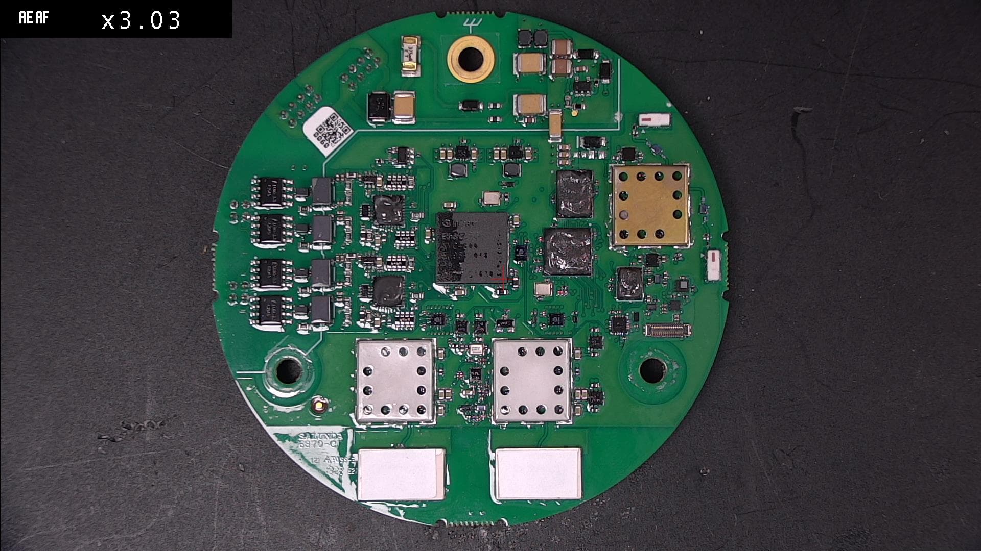
Click to zoom
Application Details
- Equipment Class
- WBT - Wideband Transmitter
- Date of Grant
- Sep 27, 2023
- Application Purpose
- Original Equipment
- Date of Application
- Sep 27, 2023
- Equipment Note
- 6870
- Frequency Range
- 6169.00000000 - 6835.00000000
- Company
- Salunda Limited
- Country
- United Kingdom
Documents & Files
Document Text
Text extracted from the exhibit documents filed with the FCC. Open a document above to read the original.
Attestation Statements
Salunda Limited 6 Avonbury Business Park Howes Lane, Bicester Oxfordshire OX26 2UA United Kingdom Tel.: +44 (0)1869 843120 Doc nr. U.S. Agent Designation for Service of Process (Applicant and U.S. Agent are Separate Parties) TO: Kiwa Nederland B.V. Wilmersdorf 50 7327 AC Apeldoorn Postbus 137 7300 AC Apeldoorn Netherlands ATTENTION: FCC Certification – Section 2.911(d)(7) Information Designated U.S. Agent Company name: Salunda USA LLC FRN 0034122804 Contact person name: Andrew Glanville Street address: 4215 S Main Street, Suite 53 ZIP/City/State 77477/Stafford/Texas Telephone number: 832-444-9800 Email address: [email protected] Signature: Date: July 14 th , 2023 This letter is to confirm that we (“the Designated U.S. Agent) have accepted the responsibility to act as the Designated U.S. Agent for Service of Process as required by section 47 CFR 2.911(d)(7) on behalf of the Applicant noted below. The Applicant acknowledges that they must maintain an agent for no less than one year after terminating all marketing and importation OR the conclusion of any Commission-related proceeding involving the equipment. The applicant further acknowledges their responsibility to inform the FCC whenever the Designated U.S. Agent information above changes. Applicant Company name: Salunda Ltd Grantee Code: 2ALTW FRN 0026436519 Contact person name: Grant Nicholls Street address: Salunda Ltd, 6 Avonbury Business Park ZIP/City/State Bicester, Oxfordshire, UK, OX26 2UA Telephone number: (+44) 1869 843120 Email address: [email protected] Signature: Date: July 14 th , 2023
Attestation Statements
Salunda Limited 6 Avonbury Business Park Howes Lane, Bicester Oxfordshire OX26 2UA United Kingdom Tel.: +44 (0)1869 843120 Certification Application Attestation Statements To Whom It May Concern: Statement for 47 CFR section 2.911(d)(5)(i) Salunda Ltd certifies that as of the date of the application the equipment FCC ID: 2ALTW18016870 for which authorization is sought is not “covered” equipment 1 prohibited from receiving an equipment authorization pursuant to section 2.903 of the FCC rules. If the equipment for which the applicant seeks authorization is produced by any of the entities identified on the current Covered List, including affiliates or subsidiaries of the named companies, the applicant must include an explanation on why the equipment is not “covered” equipment. Statement for 47 CFR section 2.911(d)(5)(ii) Salunda Ltd (“the applicant”) certifies that, as of the date of the filing of this application, the applicant - is / - is not (3) identified on the Covered List as an entity producing “covered” equipment. Date:June 19 th 2023 City:Bicester Name (2) :Grant Nicholls Function:Engineering Director FRN0026436519 Telephone number:+44 1869 843120 Email address:[email protected] Signature: 1 - The Commission’s Covered List is published by the Public Safety and Homeland Security Bureau and posted on the Commission’s website. This Covered List, which is periodically updated, identifies particular equipment, produced by particular entities, that constitutes “covered” equipment. https://www.fcc.gov/supplychain/coveredlist . (2): For FCC it must be the Grantee Code “owner” or the authorized agent. (3): double cllick on the appropriate box and select ‘’checked” then “OK”
Cover Letter(s)
Salunda Limited - Confidentiality Agreement (Two-Way) - Page 1 of 4 THIS AGREEMENT IS DATED 4 th May 2017 PARTIES (1) Salunda Limited incorporate and registered in England and Wales with company number 05230854 whose registered office is at 6, Avonbury Business Park, Howes Lane, Bicester, Oxfordshire, OX26 2UA, United Kingdom (Salunda) ; and (2) ________. With company number 2500898 whose registered address is at __________________, United Kingdom, _______ (Customer). BACKGROUND Salunda and Customer desire to exchange certain Confidential Information about themselves including but not limited to such product, hardware, software, technical, operational, business, financial, procedural and other proprietary information as each party determines, in its sole discretion, is reasonably necessary or desirable to disclose for the purposes of evaluation, testing and use of oilfield equipment monitoring applications and equipment (Purpose). In consideration of the benefits to the parties of the disclosure of the Confidential Information, the parties have agreed to comply with the following terms in connection with the use and disclosure of Confidential Information. AGREED TERMS 1. DEFINITIONS AND INTERPRETATION 1.1 “Commencement Date” means 1 May 2017. “Confidential Information” means all confidential information disclosed by the Disclosing Party or its Representatives to the Receiving Party and its Representatives from the Commencement Date of this Agreement, including but not limited to any information relating to the finances, business affairs, customers, clients, suppliers, plans, intentions, or market opportunities of the Disclosing Party; and the Intellectual Property, technology, operations, processes, technical data, inventions, product development plans, manufacturing, engineering, product information, internal product photographs, product specification, guides and materials, know-how, product designs, manuals or instructions for use of the products or software of the Disclosing Party; and any information or analysis derived from Confidential Information. Confidential Information shall be disclosed in documentary or tangible form and marked “Confidential” or “Proprietary.” In the case of disclosures in non-documentary form, made orally or by visual inspection, the Disclosing Party shall confirm in writing the fact and general nature of each such disclosure within thirty (30) days after it is made. Notwithstanding the foregoing, it is agreed that failure to mark documents or reduce oral disclosures to writing shall not alleviate the Receiving Party of its obligations under this Agreement if the disclosed information would reasonably be considered confidential based upon the nature of the information or the circumstances surrounding its disclosure 1.2 “Disclosing Party” means a party to this Agreement which discloses or makes available directly or indirectly Confidential Information to the Receiving Party. 1.3 Receiving Party” means a party to this Agreement which receives or obtains directly or indirectly Confidential Information. 1.4 “Representative” means employees, agents and other representatives of a party. 1.5 “Intellectual Property” means patents, rights to inventions, copyright and related rights, trade marks and service marks, business names and domain names, rights in get-up and trade dress, goodwill and the right to sue for passing off, rights in designs, product specification and information, rights in computer software, source codes, database rights, rights to use, and protect the confidentiality of, confidential information (including know-how and trade Salunda Limited - Confidentiality Agreement (Two-Way) - Page 2 of 4 secrets) and all other intellectual property rights and all similar or equivalent rights or forms of protection which subsist or will subsist now or in the future in any part of the world. 1.6 For the purposes of this Agreement, information shall not be deemed to be Confidential Information if such information: 1.6.1 is or becomes generally available to the public other than as a result of disclosure by the Receiving Party or its Representatives; or 1.6.2 is known by the Receiving Party prior to disclosure by the Disclosing Party; or 1.6.3 is or becomes available to the Receiving Party or its Representatives from a source not under obligation of confidentiality to the Disclosing Party; or 1.6.4 can be demonstrated through written records to have been independently developed by the Receiving Party without the use of or reference to the Confidential Information of the Disclosing Party. 2. OBLIGATIONS OF THE RECEIVING PARTY 2.1 The existence and terms of this Agreement and the existence of any discussions between the parties under this Agreement are Confidential Information of both parties and are protected by each party’s obligations of confidentiality hereunder. 2.2 Each party shall use the Confidential Information solely for the Purpose. The Receiving Party will not disclose or otherwise make known any of the Confidential Information of the Disclosing Party to anyone, except those of its Representatives who have a need to know the Confidential Information for the Purpose and who are bound by the non- use and non-disclosure obligations set forth in this Agreement. Each party shall accept the disclosures of the Confidential Information by the other party on a confidential basis and shall exercise the same degree of care with respect to the other party’s Confidential Information as it would its own Confidential Information. 2.3 The Receiving Party may disclose Confidential Information to the extent such Confidential Information is required to be disclosed by law, by any governmental or other regulatory authority, or by a court or other authority of competent jurisdiction provided that, to the extent it is legally permitted to do so, it gives the Disclosing Party as much notice of this disclosure as possible and, so that the Disclosing Party may seek a protective …
Text truncated - open the document above for the full version.
Cover Letter(s)
Salunda Limited 6 Avonbury Business Park Howes Lane, Bicester Oxfordshire OX26 2UA United Kingdom Tel.: +44 (0)1869 843120 E-mail: [email protected] Web: www.salunda.com Salunda Ltd. Registered in England No 5230854 Registered Office: 6 Avonbury Business Park, Howes Lane, Bicester, OX26 2UA Declaration of Authorization We Name: Salunda Ltd Address: 6 Avonbury Business Park, Howes Lane City: Bicester Country: United Kingdom Declare that: Name Representative of agent: Daniel Sims Agent Company name: RN Electronics Ltd Address: Arnolds Court, Arnolds Farm Lane City: Mountnessing, Brentwood Country: United Kingdom is authorized to apply for Certification of the following product(s): Product description: 6870 Type designation: C6 Trademark: Crew Hawk Validity/expiry date: July 31 st 2024 on our behalf. Date: July 31 st 2023 City: Bicester Name: Grant Nicholls Function: Engineering Director Signature:
Cover Letter(s)
FCC, Request for non-disclosure Date: 01-Nov-2022 RF_501, Issue 8 Page 1 of 1 Company Name: Salunda Ltd Address: Unit 6, Avonbury Business Park City: Bicester Country: United Kingdom To: Telefication B.V., Dept. FCC TCB Edisonstraat 12A 6902 PK ZEVENAAR The Netherlands Subject: Request for confidentiality FCC ID: 2ALTW18016870 Reference number: ###### Dear FCC TCB, 1. Long-Term Confidentiality Pursuant to 47 CFR Section 0.459(a) & (b), we hereby requests non-disclosure and confidential treatment of the following materials submitted in support of FCC certification application: Bill(s) of Material Block Diagrams Operational Description Schematic Diagrams Tune-up Procedure Internal Photos User Manual Above materials contain secrets, proprietary and technical information, which would customarily be guarded from competitors under 47 CFR, section 0.457(d)(2). Disclosure or publication or any portion of this company confidential material to other parties could cause substantial competitive harm and provide unjustified benefits for competitors. Salunda Limited has spent substantial effort in developing this product and it is one of the first of its kind in industry. Having the subject information easily available to "competition" would negate the advantage they have achieved by developing this product. Not protecting the details of the design will result in financial hardship. The user manual contains proprietary technical information, all sales and distribution of the of the user manual is under NDA that restricts the disclosure of the information. Internal photos and user manuals are prevented from becoming public or disclosed by means of not making the document available online and by NDA between Salunda and the party receiving internal photos or user manuals. The subject is not serviceable item and therefore no service documents are available to professional designated technicians. All sales of the subject are under NDA including third party sales and that the final user of the device is subject to the NDA. 2. Short-Term Confidentiality (STC) Pursuant to Public Notice DA 04-1705 of the Commission’s policy, in order to comply with the marketing regulations in 47 CFR §2.803 and the importation rules in 47 CFR §2.1204, applicant hereby requests Short-Term Confidential treatment of the following materials (See notes below): Internal Photos User’s Manual Test Set-up Photos External Photos FCC, Request for non-disclosure Date: 01-Nov-2022 RF_501, Issue 8 Page 1 of 1 Justification: Date: 18 th August 2023 Name and signature of applicant: Daniel Sims (Agent) Notes: 1) A document or type of document can only have ONE type of confidentiality! 2) Short-Term confidentiality is in principle for 45 days from date of grant; it can be extended max 3 times (total time 180 days max.)! The planned date should stated in the RF731 application form. 3) FCC must be informed when marketing begins earlier. 4) Release takes place automatically thus extension must be requested in time. Telefication does not remind you of this! 5) Request for extension or for release must be received by Telefication at least 7 days before date of actual marketing or before expiration of the STC period
Cover Letter(s)
RF_734_05 FCC Modular Approval Request Page 1 of 3 28-12-2022 Modular Approval Request FCC(KDB 996369 D01 & Part 15.212) FCC ID: _________2ALTW18016870__________ Items to be covered by Single modular transmitters. Answer from applicant 1. The radio elements must have the radio frequency circuitry shielded. Physical components and tuning capacitor(s) may be located external to the shield, but must be on the module assembly. Yes, shields are used over RF circuitry. 2. The module must have buffered modulation/data inputs to ensure that the device will comply with Part 15 requirements with any type of input signal. Yes, inputs/outputs are buffered. 3. The module must contain power supply regulation on the module Yes, regulation is present. 4. The module must contain a permanently attached antenna, or contain a unique antenna connector, and be marketed and operated only with specific antenna(s), per §§ 15.203, 15.204(b), 15.204(c), 15.212(a), 2.929(b). Yes, permanently attached integral antennae are used. 5.The module must demonstrate compliance in a stand-alone configuration. Yes, module tested 10cm from host device/config, and included AC conducted emissions testing. 6.The module must be labeled with its permanently affixed FCC ID label, or use an electronic display (see KDB Publication 784748). Yes, module is labelled with FCC ID 7.The module must comply with all specific rules applicable to the transmitter, including all the conditions provided in the integration instructions by the grantee. Yes, rule parts tested are also listed in the user manual, along with integration instructions. 8.The module must comply with RF exposure requirements. Yes, module complies with RF exposure requirements, which are listed in the user/installation manual Name and surname of applicant (or authorized representative): Daniel Sims (Agent) On behalf of RN Electronics Ltd. Date: __18 th August 2023___ Signature:
Cover Letter(s)
Salunda Limited 6 Avonbury Business Park Howes Lane, Bicester Oxfordshire OX26 2UA United Kingdom Tel.: +44 (0)1869 843120 E-mail: [email protected] Web: www.salunda.com Salunda Ltd. Registered in England No 5230854 Registered Office: 6 Avonbury Business Park, Howes Lane, Bicester, OX26 2UA Declaration of Non-Denial of federal benefits & acceptance of grantee responsibilities Name: Salunda Ltd Address: 6 Avonbury Business Park, Howes Lane City: Bicester, OX26 2UA Country: United Kingdom We certify that we are not subject to denial of federal benefits, that includes FCC benefits, pursuant to Section 5301 of the Anti-Drug Abuse Act of 1988, 21 U.S.C. 862. Further, no party, as defined in 47 CFR 1.2002 (b), to the application is subject to denial of federal benefits, that includes FCC benefits. We also declare that the information provided to the FCC is true and correct to the best of our knowledge (47 CFR 2.911(d)) and we have been informed of the grantee responsibilities (47 CFR 2.909) with regard to certified equipment. Date: November 1 st , 2022 Name: Grant Nicholls Function: Engineering Director Signature:
External Photos
Salunda Limited 6 Avonbury Business Park Howes Lane, Bicester Oxfordshire OX26 2UA United Kingdom Tel.: +44 (0)1869 843120 E-mail: [email protected] Web: www.salunda.com Salunda Ltd. Registered in England No 5230854 Registered Office: 6 Avonbury Business Park, Howes Lane, Bicester, OX26 2UA Salunda Ltd – February 8 th 2023 FCC ID 2ALTW18016870 Required Exhibits for FCC Certification External Photos Salunda Limited 6 Avonbury Business Park Howes Lane, Bicester Oxfordshire OX26 2UA United Kingdom Tel.: +44 (0)1869 843120 E-mail: [email protected] Web: www.salunda.com Salunda Ltd. Registered in England No 5230854 Registered Office: 6 Avonbury Business Park, Howes Lane, Bicester, OX26 2UA
ID Label/Location Info
Salunda Limited 6 Avonbury Business Park Howes Lane, Bicester Oxfordshire OX26 2UA United Kingdom Tel.: +44 (0)1869 843120 E-mail: [email protected] Web: www.salunda.com Salunda Ltd. Registered in England No 5230854 Registered Office: 6 Avonbury Business Park, Howes Lane, Bicester, OX26 2UA
ID Label/Location Info
THIS DRAWING IS UNCONTROLLED WHEN VIEWED OUTSIDE OF SALUNDA'S PDM SYSTEM. = 0.5mm = 0.25mm = 0.1mm = 0.5° TOLERANCES 0 0.0 0.00 ANGLES SURFACE FINISH SQUARENESS PARALLELISM RUNOUT 1.6 μm Ra MAX 0.05 IN 25 MAX 0.05 IN 25 MAX 0.1 MAX ALL DIMENSIONS IN mm UNLESS OTHERWISE STATED FCC ID LABEL - GW PCB LB-07926 A PP 09/02/2023 MB PART No: DESCRIPTION REVCHANGE NOTE: DATE: CHECKED BY: DRAWN BY: TREATMENT: MATERIAL: IF IN DOUBT ASK CONTAINS TRADE SECRETS - CONFIDENTIAL AND PROPRIETARY INFORMATION BELONGING TO SALUNDA - REPRODUCTION, DISTRIBUTION OR DISCLOSURE IS STRICTLY PROHIBITED PROPORTIONAL - DO NOT SCALE SHEET 1 OF 1 SHEET SIZE A3 PROJECTION 3rd ANGLE +44(0)1865 843120 www.salunda.com APPROVED BY: GN GLOSS WHITE VINYL HIGH TACK ADHESIVE REMOVE ALL SHARP EDGES AND BURRS. SUPPLY DEGREASED AND CLEANED. MARK WITH PART No. AND REVISION No. mass: 0.00 Kg 13.0 12.0 R1.0 TYP 4 SCALE 10:1 0.1 FRONT VIEW SCALE 1:1 ISO VIEW SCALE 1:1 NOTES: MATERIAL: SUBSTRATE AND ADHESIVE SUITABLE FOR SERVICE TEMP UP TO 70 C1. BLACK TEXT ON WHITE BACKGROUND - MATT OR SATIN FINISH ALSO ACCEPTABLE2. A F B E D C 46 8 1 3572 54 1 6 8 237 E C A B D F
RF Exposure Info
RN Electronics Ltd, Arnolds Court, Arnolds Farm Lane, Brentwood, Essex, CM13 1UT, England. Registered No. UK 3051259. VAT No. 475 2328 39 Web: www.RNElectronics.com Email: [email protected] 6870 module (EUT) RF Exposure:- The 6870 module is intendedas a mobile device. Instructions to host manufacturer included in the installation manual relate to mobile use and 200mm (0.2metres) distance and the relevant RF exposure requirements. The module device has three transmitters in it, a ZigBee device with two antennas and two UWB devices with an antenna each. The UWB devices cannot transmit with each other, either one of the UWB devices can transmit at the same time as the ZigBee radio. The ZigBee radio transmits out of one of its antennas only at a time. This evaluation covers the three transmitters operating individually and either of the UWB transmitters operating with the ZigBee transmitter simultaneously. RF exposure test exemption/calculation is demonstrated using: KDB 447498 D04 Interim General RF exposure Guidance. Clause 2.1 RF exposure Test Exemptions for single source Clause2.1.4MPE-Based Exemption An alternative to the SAR-based exemption is provided in § 1.1307(b)(3)(i)(C), for a much wider frequency range, from 300 kHz to 100 GHz, applicable for separation distances greater or equal to λ/2π, where λ is the free-space operating wavelength in meters. The MPE-based test exemption condition is in terms of ERP, defined as the product of the maximum antenna gain and the delivered maximum time-averaged power.10 For this case, a RF source is an RF exempt device if its ERP (watts) is no more than a frequency-dependent value, as detailed tabular form in Appendix B. These limits have been derived based on the basic specifications on Maximum Permissible Exposure (MPE) considered for the FCC rules in § 1.1310(e)(1). Clause2.2RF Exposure Test Exemptions for Simultaneous Transmission Sources Clause 2.2.2Simultaneous Transmission with both SAR-based and MPE-Based Test Exemptions This case is described in detail in § 1.1307(b)(3)(ii)(B) and covers the situations where both SAR-based and MPE-based exemption may be considered for test exemption in fixed, mobile, or portable device exposure conditions. For these cases, a device with multiple RF sources transmitting simultaneously will be considered an RF exempt device if the condition of Formula (1) is satisfied. For these test exemptions to apply, the maximum output power, duty factor, and other applicable parameters used in the standalone ERP determination tests, must be the same, or corresponding to a more conservative choice, than those required for simultaneous transmission. The power level of the standalone SAR used to qualify for SAR test exemption, or additional test exemption, must be clearly explained in the SAR report. When simultaneous transmission SAR-based test exemptions, or when the SPLSR test exemption [Section 2.2.3] cannot be applied, enlarged zoom scan [Glossary] SAR measurements must be performed at the maximum output power required for the applicable simultaneous transmission scenarios. This power level shall account for the tune-up tolerance [Glossary] requirements of all transmitters, but not more than 2 dB lower than the maximum tune-up tolerance limit. RN Electronics Ltd, Arnolds Court, Arnolds Farm Lane, Brentwood, Essex, CM13 1UT, England. Registered No. UK 3051259. VAT No. 475 2328 39 Web: www.RNElectronics.com Email: [email protected] RN Electronics Ltd, Arnolds Court, Arnolds Farm Lane, Brentwood, Essex, CM13 1UT, England. Registered No. UK 3051259. VAT No. 475 2328 39 Web: www.RNElectronics.com Email: [email protected] Single source ZigBee transmission 2.405 - 2.48 GHz: Highest ZigBee radiated power 97.38 dBuV/m @ 3m (+2.18 dBm) from middle channel (CH18) 2440 MHz and using antenna 1. Max 5% duty cycle. So, Max time averaged power = 2.18-13.01 = -10.83 dBm or 0.083 mW. Using clause 2.1.4 MPE-Based Exemption and Table 1 (1.1307(b)(3)(i)(c) low channel Mid channel High channel Separation distance R (meters) 0.2 0.2 0.2 f(MHz) 2405 2440 2480 λ/2π (metres) 0.019853007 0.019568231 0.019252614 Table 1 (1.1307(b)(3)(i)(c) RF Source Frequency (MHz) Threshold Erp (watts) Pth (Threshold) Watts ERP 0.3 - 1.34 1920 R 2 N/A 1.34 - 30 3450 R 2 /f 2 N/A 30 - 300 3.83 R 2 N/A 300 - 1500 0.0128 R 2 f N/A 1500 - 100000 19.2 R 2 0.768 As the ZigBee device highest ERP is on middle channel and after duty correction is only 0.083 mW, the ZigBee transmitter in the module device meets the exemption from further evaluation as a single source compared to the Pth threshold limit. Single source UWB transmission 1: UWB Peak Radiated power -0.15dBm in 50 MHz, Nominal Bandwidth is 666.5 MHz, so power in 666.5 MHz = 10* Log (666.5/50) = 11.25dB correction(addition), therefore: max UWB power = -0.15+11.25 = 11.09 dBm. Max 10% duty cycle declared. So, Max time averaged radiated power = 11.09 dBm -10dB = 1.09 dBm or 1.29 mW. low channel Separation distance R (meters) 0.2 f(MHz) 6500 λ/2π (metres) 0.007345613 As the UWB 1 transmitter devices highest ERP on its channel after duty correction is only 1.29 mW, the UWB 1 transmitter in the module device meets the exemption from further evaluation as a single source compared to the Pth threshold limit. RN Electronics Ltd, Arnolds Court, Arnolds Farm Lane, Brentwood, Essex, CM13 1UT, England. Registered No. UK 3051259. VAT No. 475 2328 39 Web: www.RNElectronics.com Email: [email protected] Single source UWB transmission 2: UWB Peak radiated power -0.39dBm in 50 MHz, Nominal Bandwidth is 666.5 MHz, so power in 666.5 MHz = 10* Log (666.5/50) = 11.25dB correction(addition), therefore: max UWB power = -0.39+11.25 = 10.86 dBm. Max 10% duty cycle declared. So, Max time averaged radiated power = 10.86 dBm -10dB = 0.86 dBm or 1.22 mW. low channel Separation distance R (meters) 0.2 f(MHz) 6500 λ/2π (metres) 0.007345613 As the UWB 2 transmitter devices highest ERP on its channel aft…
Text truncated - open the document above for the full version.
Test Report
2.4 GHz SMD, Above Metal, Low Profile Mini Chip Antenna P/N 2450AT42E0100 This antenna will generally have a metal layer directly underneath for proper operation, exceptions may apply. Detail Specification: Page 1 of 8 1 L ±± 2 W ±± 3 T ±± 4 a ±± b ±± C https://www.johansontechnology.com 4001 Calle Tecate • Camarillo, CA 93012 • TEL 805.389.1166 FAX 805.389.1821 2021 Johanson Technology, Inc. All Rights Reserved Average Gain (dBi typ.)-5.0 (YZ-V) High Frequency Ceramic Solutions -2.0 (YZ-V) Feeding Point 5.6 typ. (4.5 min.) 10/28/2021 2450AT42E0100 2400 - 2480 +5°C to +35°C Total average radiated efficiency on PCB feature on "Mounting Considerations 1" ( orderable EVB p/n: 2450AT42E0100-EB1SMA) is ~30% In 50 2,000 -40 to +85°C 2 max. (CW) mm 5.00 NC 1 0.197 0.0790.008 Terminal Configuration Part Number Explanation Suffix = S Suffix = E Mechanical Specifications Evaluation Board Packing Style Johanson Technology, Inc. reserves the right to make design changes without notice. GND Ver. 4.0 1.500.0590.200.008 0.0120.30 maxmax All sales are subject to Johanson Technology, Inc. terms and conditions. 0.200.020 1 Make sure to have Pin 2 soldered to its PCB land pad but not connected to GND or input, it must be NC (or floating). Recommended Storage Conditions and Period for unused Product on T&R Humidity 45 - 75% RH 18 months max. 0.20 0.20 This antenna was designed in mind for small coin cell, wearable, IoT, 2.4 BLE, 802.11, ISM, Zigbee, etc. applications in close-range networks where metal or a battery/display covers the entire length or side of the PCB or encasement must be present directly under the antenna and there's no room for usual/typical antenna metal clearance. 0.500.008 1.500.200.0590.008 0.008 2.00 GND E.g. 2450AT42E0100S E.g. 2450AT42E0100E General Specifications P/N Suffix 2450AT42E0100-EB1SMA (comes with 1 female SMA connector) Bulk (loose pcs.) T & R Part Number Frequency (MHz) Peak Gain (dBi typ.) Return Loss (dB) Impedance (Ω) This antenna is specifically designed for PCBs that have 0.5-1mm of total thickness Operating Temp Power Capacity (W) Reel Quantity (pcs./reel) Antenna mounts directly above or below the metal layer of PCB. No antenna clearance required ever again! b T a b L W c Top View Bottom View Side View 2.4 GHz SMD, Above Metal, Low Profile Mini Chip Antenna P/N 2450AT42E0100 This antenna will generally have a metal layer directly underneath for proper operation, exceptions may apply. Detail Specification: Page 2 of 8 https://www.johansontechnology.com 4001 Calle Tecate • Camarillo, CA 93012 • TEL 805.389.1166 FAX 805.389.1821 2021 Johanson Technology, Inc. All Rights Reserved Ver. 4.0 High Frequency Ceramic Solutions Johanson Technology, Inc. reserves the right to make design changes without notice. All sales are subject to Johanson Technology, Inc. terms and conditions. 10/28/2021 Mounting Considerations 1 *Line width should be designed to match 50ohm characteristic impedance, depending on PCB material and thickness. A coplanar waveguide trace is recommended for best results. For this particular antenna It is recommended that the designer leave available slots for the matching network, even if all slots won't be used, this will prepare the PCB for the unpredictable final mass production version of the matching circuit. The antenna matching network values above are used when antenna is mounted on Johanson's evaluation board. The matching values on client’s PCB will be different. To order a pre-tuned 50 Ω EVB with a female SMA connector you see here Click here: https://www.johansontechnology.com/request-a-sample Reference p/n: 2450AT42E0100-EB1SMA Ground Plane (where other SMD components will be mounted) 30mm 6.26mm 50mm 50Ω Feed Line 3mm Top View Bottom View Ground Want the layout file? Send us a message at: https://www.johansontechnology.com/ask-a-question p/n: 2450AT42E0100-EB1SMA Matching circuit Metal bottom GND plane to be placed directly underneath yellow soldemask zone, covering entire area. 1.5 nH Matching circuit 1.5mm 0.3mm 2mm 1.5mm 0.6mm 1.0mm 0.6mm 0.5mm 0.63mm 0.63mm Floating pad 3mm 6.26mm * 3.3 nH 2.0 pF 2.4 GHz SMD, Above Metal, Low Profile Mini Chip Antenna P/N 2450AT42E0100 This antenna will generally have a metal layer directly underneath for proper operation, exceptions may apply. Detail Specification: Page 3 of 8 Return Loss https://www.johansontechnology.com 4001 Calle Tecate • Camarillo, CA 93012 • TEL 805.389.1166 FAX 805.389.1821 2021 Johanson Technology, Inc. All Rights Reserved All sales are subject to Johanson Technology, Inc. terms and conditions. Johanson Technology, Inc. reserves the right to make design changes without notice. Ver. 4.0 High Frequency Ceramic Solutions Typical Electrical Characteristics (T=25 °C) 10/28/2021 2.22.42.62.82.03.0 -15 -10 -5 -20 0 freq, GHz dB(S(1,1)) m118 m122 m123 m118 freq= dB(S(1,1))=-11.343 2.440GHz m122 freq= dB(S(1,1))=-5.691 2.400GHz m123 freq= dB(S(1,1))=-5.746 2.480GHz The designer should not be highly concerned of the fact that the antenna only demonstrates a -5dB S11 level at the band edges. The antenna has sufficient gain at the band edges to satisfy the applications and uses a high dielectric constant ceramic giving it some detuning resilience to capacitivel loading effects. This antenna is designed for close proximity applications such as the ones mentioned on page 1. 2.4 GHz SMD, Above Metal, L…
Text truncated - open the document above for the full version.
Contact Information
Applicant
Grant Nicholls(Engineering Director)
Technical Contact
Salunda LtdGrant Nicholls
[email protected]+441869843120
Unit 6, Avonbury Business Park · Bicester · United Kingdom
Non-Technical Contact
Salunda LtdCurran William
[email protected]+441869843120
Test Firm
Kiwa LtdClint Hilling
[email protected]44 1277 352219
Technical Specifications
| # | Rule Parts | Frequency Range | Power Output |
|---|---|---|---|
| 1 | 15.250 | 6.17 GHz - 6.83 GHz | 13.00 mW |
Other Applications from Salunda Limited
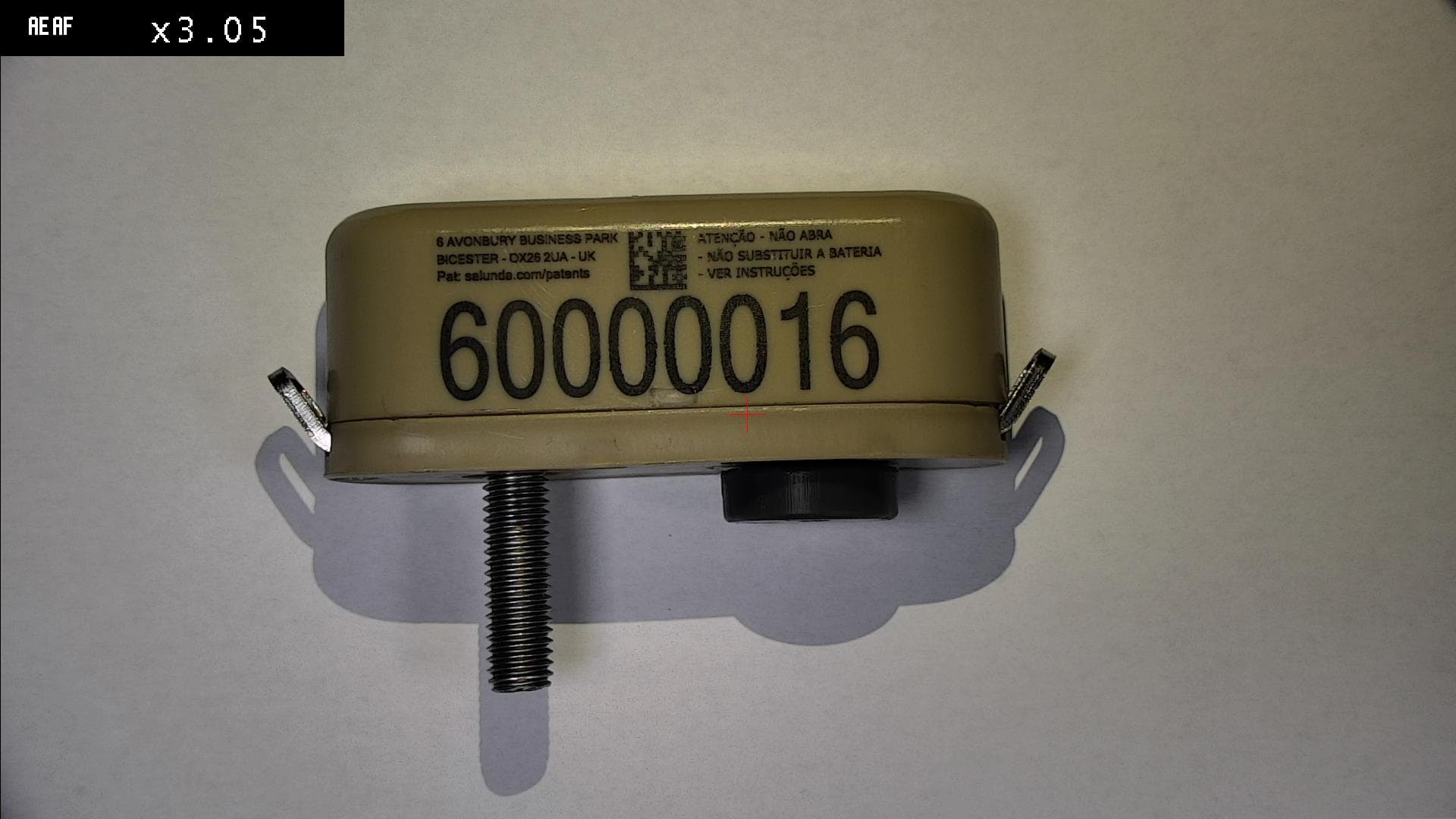
2ALTW17012020
Jan 10, 2024LHW 1701 E 2.0-20
Equipment Class
DTS - Digital Transmission System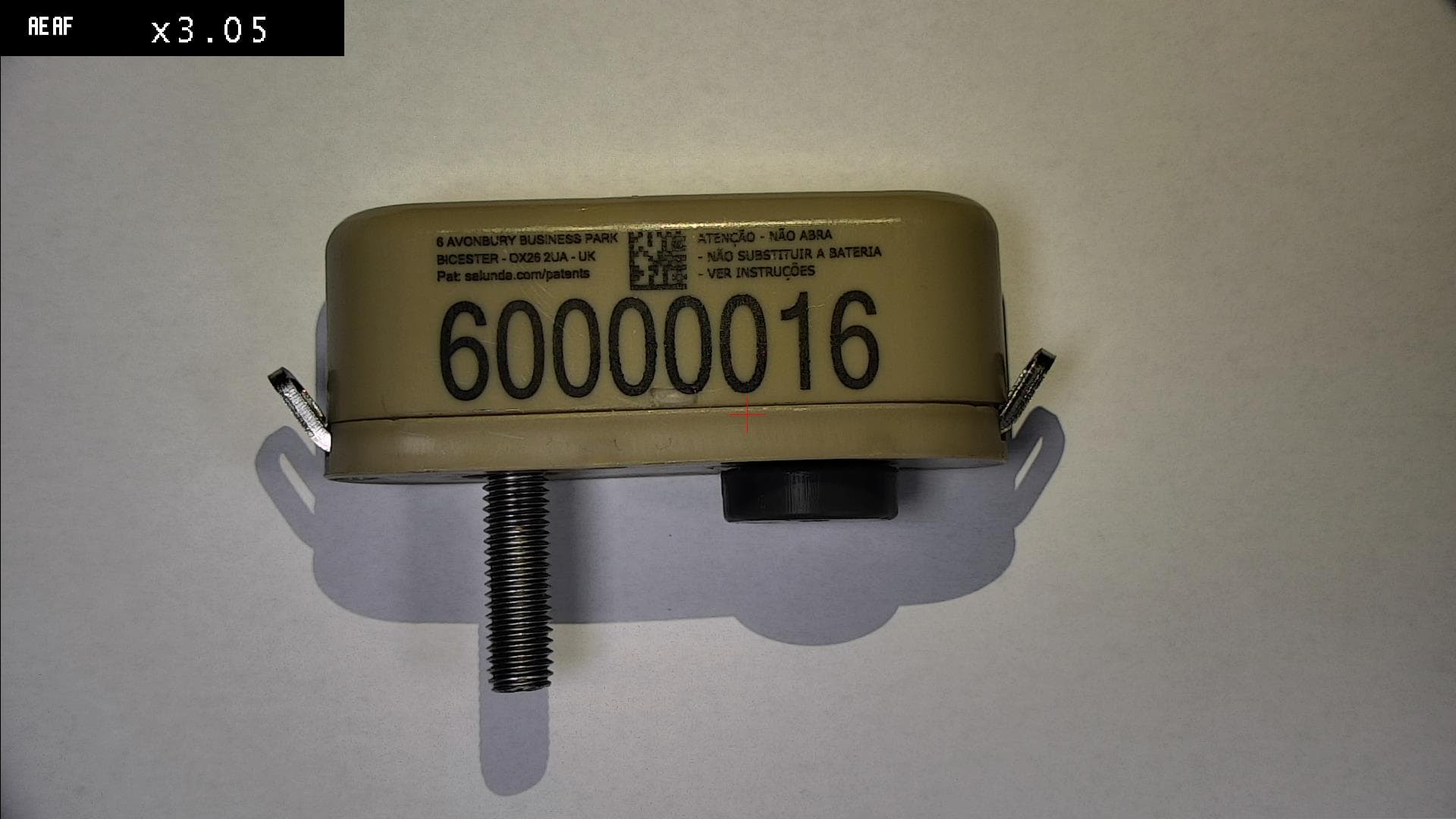
2ALTW170120
Oct 24, 2023LHW 1701 E 2.0
Equipment Class
DTS - Digital Transmission System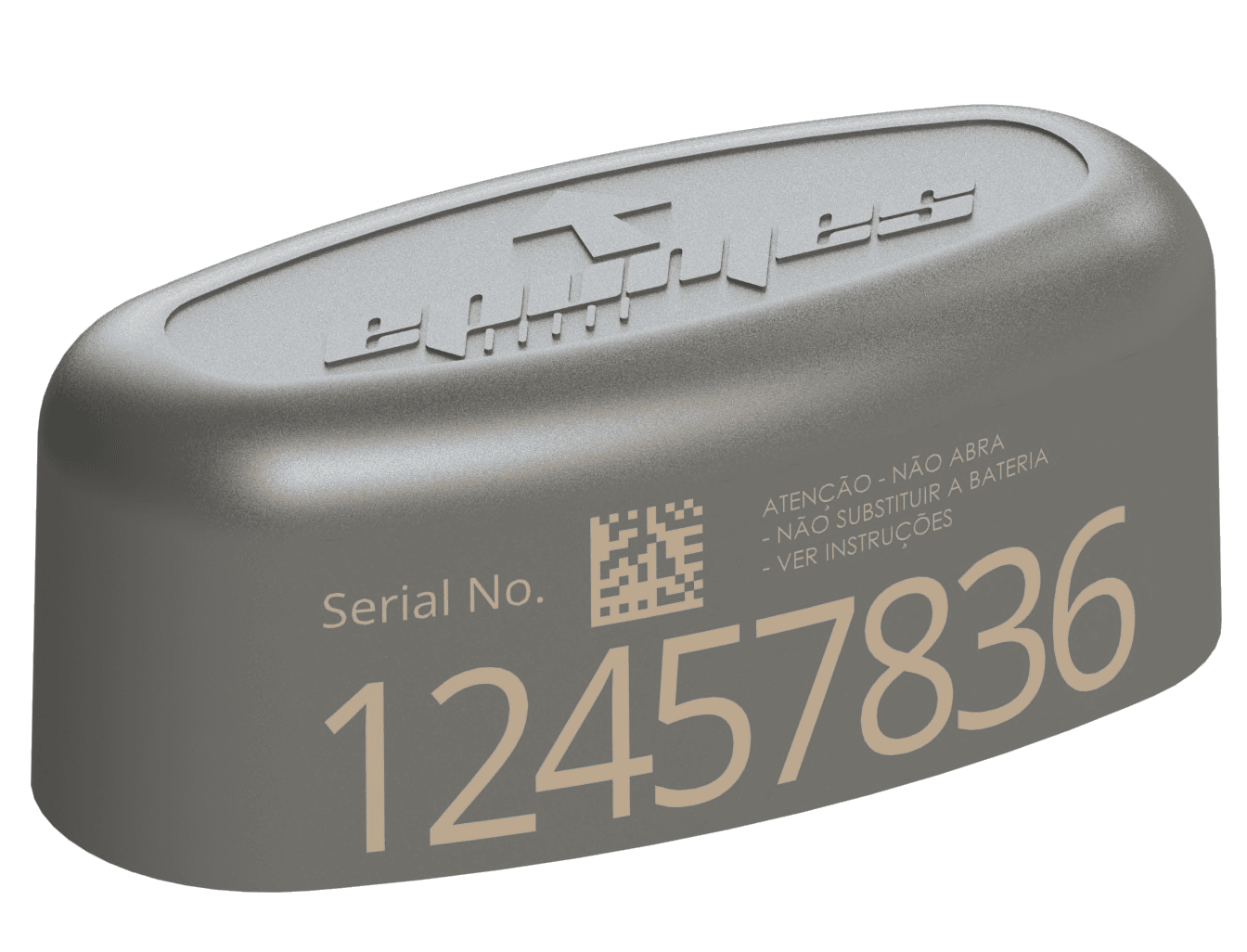
2ALTW170116
Dec 15, 2022LHW 1701 E 1.6
Equipment Class
DTS - Digital Transmission System