2ALYUHDR-AC54K OPTICAL VIDEO CAMERA
Shenzhen PA. Times Technology Co., Ltd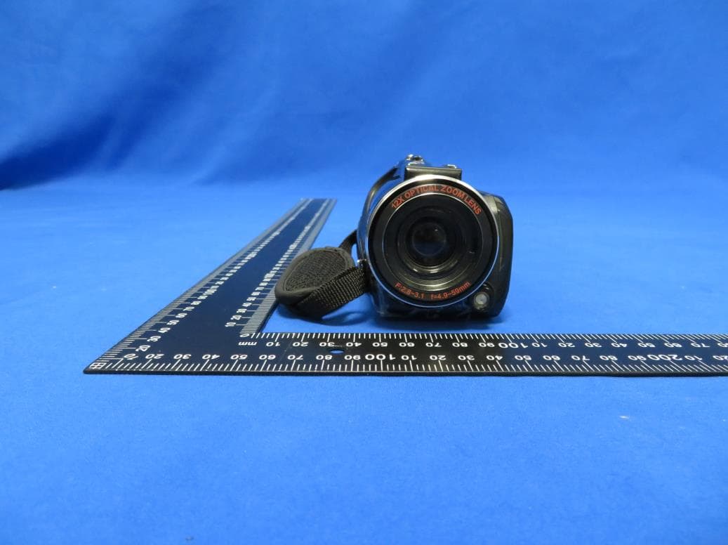
Click to zoom
Application Details
- Equipment Class
- DTS - Digital Transmission System
- Date of Grant
- Jul 08, 2020
- Application Purpose
- Original Equipment
- Date of Application
- Jul 08, 2020
- Equipment Note
- 4K OPTICAL VIDEO CAMERA
- Frequency Range
- 2412.00000000 - 2462.00000000
- Country
- China
Documents & Files
Document Text
Text extracted from the exhibit documents filed with the FCC. Open a document above to read the original.
Users Manual
Overview Thankyouforpurchasingthisportabledigitalvideocamera, thiscamerafeaturesvideorecordingat4K.Withresolutionof 2880*2160,itadoptedSony1/3-inchimagesensor,H.264 videoencodingformat,thevideofilestorageusageissmall whileithashighimagequality!Youcanconnectyourcamera viaWi-FiusingyoursmartPhoneremotely,toviewthecamera livescreenanduseyourphonetorecordorshooting. SafetyInstructions Donotdrop,impactorpuncturethecamera. Donotexposethecameratohigh/lowtemperature, excessivedust,humidityorstrongvibration,otherwise theproductmaybedamaged. Donotusecorrosivechemicalsorsolventstocleanthe product. Donotdisassemblethiscameraorattempttorepairor modifyitinanymanner,ifthereisanydamagetothe camera,stopusingthecameraandreturnthisproductto thestorewhereyouhavepurchaseditfrom,theproduct willbesentbacktothecompanyandfix. Cautions Keepchildrenawayfromtheproduct,accessoriesand itspackagingmaterials,itmaycausesuffocation. Donotputtheproductinafire,otherwiseitmaycause anexplosion. Removethebatteryifthecameraisnotgoingtobeused forlongperiods,andpleasefully-chargedthebattery beforeusingitagain. TABLEOFCONTENTS GettingtoKnowYourCamera.......................................................1 StandardAccessories...........................................................1 ChargingtheBattery.............................................................1 ComponentIntroduction.......................................................3 GettingStarted.................................................................................7 InsertinganSDCard............................................................7 LoadingBattery.....................................................................8 RecordingMode....................................................................9 PhotoMode..........................................................................13 SettingMode........................................................................17 PlayBack..............................................................................18 ConnectingtoTV................................................................22 ConnectingtotheComputer.............................................23 APPUsing......................................................................................24 DownloadingtheAPP........................................................24 HowtoConnectWi-Fi........................................................24 GetStarted...........................................................................26 TechnicalParameters...................................................................30 Troubleshooting.............................................................................31 GettingtoKnowYourCamera StandardAccessories 4KUltraHDCameraInfraredremotecontrol BatteryHDMICable ChargerUserManual USBCableWarrantyCard Theaboveareallaccessories,ifthereisanymissing, pleasecontactthesellerforreplacement. ChargingtheBattery Beforeusingthecamera,youmustloadandchargethe battery ChargingwiththeCharger Connectto 100-220V socket Note:Insertthebatteryintothechargertochargeit,the indicatorlightwillberedwhencharging;Theindicator lightwillturngreenwhenthechargingiscompleted. ChargingwithUSBCable(DirectCharge) 1.PleaseConnecttheUSBCabletothechargingadapter whencameraisrunninglow. 2.ConnecttheothersidetotheCamera’sUSBcharging interface. 3.Theindicatorlightwillberedwhencharging;Theindicator lightwillturngreenwhenthechargingiscompleted. Note: 1.Whenusingthecharger,pleaseinstallthebatteryin thechargerslotcorrectly. 2.Fordirectcharge,pleaseusethe5V/2A-2.5Acharging adapterforcharging. 3.WhenusingtheUSBCabletocharge,ifchargeduring workingcondition,thecamerawillautomaticallyshut downafterthechargingadapterispoweredoff. ComponentIntroduction RearView ⑦ ⑧ ⑨ ⑩ ⑪ ⑫ ⑬ ① ② ③ ④ ⑤ ⑥ I III V IV II ⑭ Forthefunctiondescriptionoftherelatedpartsintheabove figure,pleaserefertothefollowingtable. No.NameFunctiondescription 1IPSTouchPanel Screenpreviewandvideo/photo playback 2 Hotshoe interface Mounthotshoeproducts 3StateLightDisplayofmodestatus 4T/WZoomButton Invideo/PhotoMode,pullleft/ righttozoomin/out;InPlayback Mode,pulltoswitch photos/videosInMenu,pullto menuselection;InVideo Playback,pulltoadjustthe volume. 5PhotoButton Two-stagebutton,taptofocus andpresstophotoinphoto mode. 6Modedial Record 、 Photo 、 SettingMode : SETStandsforSettingMode StandsforRecordMode StandsforPhotoMode 7VideoButton “START/STOP”isthe recording/stopbutton; Stopplaybackwhenthevideois playing. 8LEDLightTurnon/offtheLEDLight Switch 9 Battery compartment switch Toggletotherighttoopenthe batterycompartment. 10 Battery Compartment LoadNP-120Battery. 11I/OInterface 10PINUSBinterface : Access theUSBCabletocharge Accesstoanexternal microphoneandcharging with“one-to-two”cableswitcher HDMI : ExternalHDCableto connecttoTV. 12 MenuButtonPresstoentertheMenu. DISPButton Presstoswitchscreendisplay mode. PowerButtonPowerOn/Off. PlaybackButtonPresstoentertheplaybackmode “Delete”Shortcut Presstodeleterecentvideosor photos. 13 Built-in microphone Recordingsound. 14SDslotOpenandinserttheSDCard. FrontView Forthefunctiondescriptionoftherelatedpartsintheabove figure,pleaserefertothefollowingtable No.NameFunctionDescription 1LensFraming. 2HornPlaysbacksounds. 3LEDlightLightingassist. 4 Infrared remote-control receiver Receivingremote command. 51/4TripodSocketTripodinstallation. 6 Handstrap mountinghole Installadjustablehand strap. ⑥ ① ⑤ ③ ② ④ GettingStarted InsertinganSDCard 1.OpentheSDcover. 2.Insertthememorycardinthedirectionshownuntilyou hear“Clicks”. 3.ClosetheSDcover. ※OpentheSDcoverandpressthememorycard. Note: 1.Whenusingforthefirsttime,formattheSDcard Onthisunit.TheSDcardneedstobeClass10. 2.DonotforcefullyremovetheSDcardwhileworking, otherwiseitmaycauselossoffilesormachine damage. LoadingBattery 1.PushtheOPENbuttontotherightasshown. 2.Thebatterycompartmentpopsopen,insertsalithium battery. 3.Closethebatterycompartment. Note: 1.Donotviolentlyopenthebatterycompartmentand removethebatter…
Text truncated - open the document above for the full version.
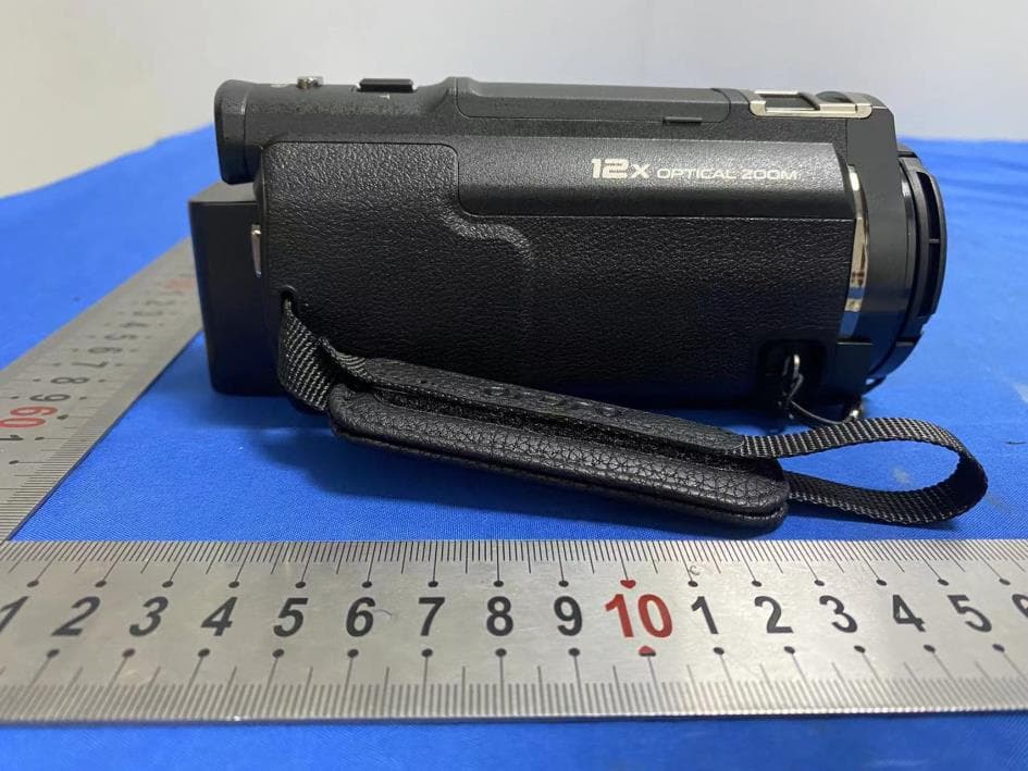
External Photos
Report No.: 2006RSU061-UE 1 of 4 EUT External Photograph (1) EUT Photo (2) EUT Photo Report No.: 2006RSU061-UE 2 of 4 (3) EUT Photo (4) EUT Photo Report No.: 2006RSU061-UE 3 of 4 (5) EUT Photo (6) EUT Photo Report No.: 2006RSU061-UE 4 of 4 (7) EUT Photo (8) EUT Photo
Internal Photos
Report No.: 2006RSU061-UE 1 of 4 EUT Internal Photograph (1) EUT Photo (2) EUT Photo Report No.: 2006RSU061-UE 2 of 4 (3) EUT Photo (4) EUT Photo Report No.: 2006RSU061-UE 3 of 4 (5) EUT Photo (6) EUT Photo Report No.: 2006RSU061-UE 4 of 4 (7) EUT Photo
RF Exposure Info
MRT Technology (Suzhou) Co., Ltd Report No.: 2006RSU061-U2 Phone: +86-512-66308358 Report Version: V01 Web: www.mrt-cert.com Issue Date: 07-08-2020 Page Number: 1 of 7 RF Exposure Evaluation Declaration FCC ID: 2ALYUHDR-AC5 APPLICANT: Shenzhen Pa. Times Technology Co., Ltd Application Type: Certification Product: 4K OPTICAL VIDEO CAMERA Model No.: HDR-AC5 Serial Model No.: AC5, AC5S, AC5P Brand Name: ORDRO FCC Classification: Digital Transmission System (DTS) Test Procedure(s): KDB 447498 D01v06 Reviewed By: ( Jame Yuan ) Approved By: ( Robin Wu ) The test results relate only to the samples tested. The test results shown in the test report are traceable to the national/international standards through the calibration of the equipment and evaluated measurement uncertainty herein. The test report shall not be reproduced except in full without the written approval of MRT Technology (Suzhou) Co., Ltd. Report No.: 2006RSU061-U2 Page Number: 2 of 7 Revision History Report No. Version Description Issue Date Note 2006RSU061-U2 Rev. 01 Initial Report 07-08-2020 Valid Report No.: 2006RSU061-U2 Page Number: 3 of 7 1. PRODUCT INFORMATION 1.1. Equipment Description Note: The different models are only for marketing different clients, others are the same. 1.2. Product Specification Subjective Product Name: 4K OPTICAL VIDEO CAMERA Model No.: HDR-AC5 Serial Model No.: AC5, AC5S, AC5P Brand Name: ORDRO Wi-Fi Specification: 802.11b/g/n Frequency Range: 802.11b/g/n-HT20: 2412 ~ 2462 MHz 802.11n-HT40: 2422 ~ 2452 MHz Type of Modulation: 802.11b: DSSS 802.11g/n: OFDM Data Rate: 802.11b: 1/2/5.5/11Mbps 802.11g: 6/9/12/18/24/36/48/54Mbps 802.11n: up to 150Mbps Antenna Type: FPC Antenna Antenna Gain: 1.63dBi Report No.: 2006RSU061-U2 Page Number: 4 of 7 2. RF Exposure Evaluation 2.1. Limits SAR Test Exclusion Thresholds for 100 MHz - 6 GHz and ≤ 50 mm Approximate SAR Test Exclusion Power Thresholds at Selected Frequencies and Test Separation Distances are illustrated in the following Table. The equation and threshold in Note 1 must be applied to determine SAR test exclusion. MHz 5 10 15 20 25 mm 150 39 77 116 155 194 SAR Test Exclusion Threshold (mW) 300 27 55 82 110 137 450 22 45 67 89 112 835 16 33 49 66 82 900 16 32 47 63 79 1500 12 24 37 49 61 1900 11 22 33 44 54 2450 10 19 29 38 48 3600 8 16 24 32 40 5200 7 13 20 26 33 5400 6 13 19 26 32 5800 6 12 19 25 31 MHz 30 35 40 45 50 mm 150 232 271 310 349 387 SAR Test Exclusion Threshold (mW) 300 164 192 219 246 274 450 134 157 179 201 224 835 98 115 131 148 164 900 95 111 126 142 158 1500 73 86 98 110 122 1900 65 76 87 98 109 2450 57 67 77 86 96 3600 47 55 63 71 79 5200 39 46 53 59 66 5400 39 45 52 58 65 5800 37 44 50 56 62 Note: The 1-g and 10-g SAR test exclusion thresholds for 100 MHz to 6 GHz at test separation distances ≤ 50 mm are determined by: Report No.: 2006RSU061-U2 Page Number: 5 of 7 [(max. power of channel, including tune-up tolerance, mW)/(min. test separation distance, mm)] * [√f(GHz)] ≤ 3.0 for 1-g SAR and ≤ 7.5 for 10-g extremity SAR, where ⚫ f(GHz) is the RF channel transmit frequency in GHz ⚫ Power and distance are rounded to the nearest mW and mm before calculation ⚫ The result is rounded to one decimal place for comparison ⚫ 3.0 and 7.5 are referred to as the numeric thresholds in the step 2 below The test exclusions are applicable only when the minimum test separation distance is ≤ 50 mm and for transmission frequencies between 100 MHz and 6 GHz. When the minimum test separation distance is < 5 mm, a distance of 5 mm according to 5) in section 4.1 is applied to determine SAR test exclusion. Report No.: 2006RSU061-U2 Page Number: 6 of 7 2.2. Test Result of RF Exposure Evaluation Product 4K OPTICAL VIDEO CAMERA Test Item RF Exposure Evaluation Test Mode Frequency Band (MHz) Maximum Output Power SAR Test Exclusion Threshold (mW) (dBm) (mW) 2.4G Wi-Fi 2412 ~ 2462 9.70 9.33 10 Note: Per FCC KDB 447498 D01v06, the SAR exclusion threshold for distances<50mm is defined by the following equation: Based on the maximum conducted power (Include Tune-up Power) of 2.4G Wi-Fi and the antenna to use separation distance, Wi-Fi SAR was not required; ( 9.33mW 5 ) * √ 2.462 = 2.93 < 3.00 Note: When the minimum test separation distance is < 5 mm, a distance of 5 mm is applied to determine SAR test exclusion. The End Report No.: 2006RSU061-U2 Page Number: 7 of 7 Appendix A - EUT Photograph Refer to “2006RSU061-UE” file.
Test Report
MRT Technology (Suzhou) Co., Ltd Report No.: 2006RSU061-U1 Phone: +86-512-66308358 Report Version: V01 Web: www.mrt-cert.com Issue Date: 07-09-2020 Page Number: 1 of 102 FCC ID: 2ALYUHDR-AC5 APPLICANT: Shenzhen Pa. Times Technology Co., Ltd Application Type: Certification Product: 4K OPTICAL VIDEO CAMERA Model No.: HDR-AC5 Serial Model No.: AC5, AC5S, AC5P Brand Name: ORDRO FCC Classification: Digital Transmission System (DTS) FCC Rule Part(s): Part 15 Subpart C (Section 15.247) Test Procedure(s): ANSI C63.10-2013 Test Date: June 28 ~ July 07, 2020 MEASUREMENT REPORT FCC PART 15.247 WLAN 802.11b/g/n Reviewed By: ( Jame Yuan ) Approved By: ( Robin Wu ) The test results relate only to the samples tested. This equipment has been shown to be capable of compliance with the applicable technical standards as indicated in the measurement report and was tested in accordance with the measurement procedures specified in ANSI C63.10-2013. Test results reported herein relate only to the item(s) tested. The test report shall not be reproduced except in full without the written approval of MRT Technology (Suzhou) Co., Ltd. Report No.: 2006RSU061-U1 Page Number: 2 of 102 Revision History Report No. Version Description Issue Date Note 2006RSU061-U1 Rev. 01 Initial Report 07-09-2020 Valid Report No.: 2006RSU061-U1 Page Number: 3 of 102 CONTENTS Description Page General Information ........................................................................................................................ 5 1. INTRODUCTION ...................................................................................................................... 6 1.1. Scope ........................................................................................................................... 6 1.2. MRT Test Location ....................................................................................................... 6 2. PRODUCT INFORMATION ...................................................................................................... 7 2.1. Feature of Equipment under Test ................................................................................. 7 2.2. Product Specification Subjective to this Report ............................................................ 7 2.3. Working Frequencies for this report .............................................................................. 8 2.4. Test Mode .................................................................................................................... 8 2.5. Test Software ............................................................................................................... 8 2.6. Duty Cycle .................................................................................................................... 9 2.7. EMI Suppression Device(s)/Modifications ................................................................... 10 2.8. Labeling Requirements ............................................................................................... 10 3. DESCRIPTION of TEST ......................................................................................................... 11 3.1. Evaluation Procedure .................................................................................................. 11 3.2. AC Line Conducted Emissions .................................................................................... 11 3.3. Radiated Emissions .................................................................................................... 12 4. ANTENNA REQUIREMENTS................................................................................................. 13 5. TEST EQUIPMENT CALIBRATION DATE ............................................................................. 14 6. MEASUREMENT UNCERTAINTY ......................................................................................... 16 7. TEST RESULT ....................................................................................................................... 17 7.1. Summary .................................................................................................................... 17 7.2. 6dB Bandwidth Measurement ..................................................................................... 18 7.2.1. Test Limit ................................................................................................................ 18 7.2.2. Test Procedure used ............................................................................................... 18 7.2.3. Test Setting ............................................................................................................. 18 7.2.4. Test Setup .............................................................................................................. 18 7.2.5. Test Result .............................................................................................................. 19 7.3. Output Power Measurement ....................................................................................... 24 7.3.1. Test Limit ................................................................................................................ 24 7.3.2. Test Procedure Used .............................................................................................. 24 7.3.3. Test Setting ............................................................................................................. 24 7.3.4. Test Setup .............................................................................................................. 25 Report No.: 2006RSU061-U1 Page Number: 4 of 102 7.3.5. Test Result of Output Power ................................................................................... 26 7.4. Power Spectral Density Measurement ........................................................................ 28 7.4.1. Test Limit ..........................................................................................…
Text truncated - open the document above for the full version.
Test Report
Report No.: 2006RSU061-U1 Page Number: 43 of 102 802.11n-HT40 Out-of-Band Emissions Channel 03 (2422MHz) 100kHz PSD reference Level Low Band Edge Spurious Emission Channel 06 (2437MHz) 100kHz PSD reference Level Spurious Emission Report No.: 2006RSU061-U1 Page Number: 44 of 102 Channel 09 (2452MHz) 100kHz PSD reference Level High Band Edge Spurious Emission Report No.: 2006RSU061-U1 Page Number: 45 of 102 7.6. Radiated Spurious Emission Measurement 7.6.1.Test Limit All out of band emissions appearing in a restricted band as specified in Section 15.205 of the Title 47 CFR must not exceed the limits shown in Table. FCC Part 15.209 Limit Frequency [MHz] Field Strength [V/m] Measured Distance [Meters] 0.009 - 0.490 2400/F (kHz) 300 0.490 - 1.705 24000/F (kHz) 30 1.705 - 30 30 30 30 - 88 100 3 88 - 216 150 3 216 - 960 200 3 Above 960 500 3 7.6.2.Test Procedure Used ANSI C63.10-2013 Section 6.3 (General Requirements) ANSI C63.10-2013 Section 6.4 (Standard test method below 30MHz) ANSI C63.10-2013 Section 6.5 (Standard test method above 30MHz to 1GHz) ANSI C63.10-2013 Section 6.6 (Standard test method above 1GHz) 7.6.3.Test Setting Table 1 - RBW as a function of frequency Frequency RBW 9 ~ 150 kHz 200 ~ 300 Hz 0.15 ~ 30 MHz 9 ~ 10 kHz 30 ~ 1000 MHz 100 ~ 120 kHz >1000MHz 1 MHz Report No.: 2006RSU061-U1 Page Number: 46 of 102 Quasi-Peak Measurements below 1GHz 1. Analyzer center frequency was set to the frequency of the radiated spurious emission of interest 2. Span was set greater than 1MHz 3. RBW = as specified in Table 1 4. Detector = CISPR quasi-peak 5. Sweep time = auto couple 6. Trace was allowed to stabilize Peak Measurements above 1GHz 1. Analyzer center frequency was set to the frequency of the radiated spurious emission of interest 2. RBW = 1MHz 3. VBW = 3MHz 4. Detector = peak 5. Sweep time = auto couple 6. Trace mode = max hold 7. Trace was allowed to stabilize Average Measurements above 1GHz 1. Analyzer center frequency was set to the frequency of the radiated spurious emission of interest 2. RBW = 1MHz 3. VBW; If the EUT is configured to transmit with duty cycle ≥ 98%, set VBW = 10 Hz. If the EUT duty cycle is < 98%, set VBW ≥ 1/T. T is the minimum transmission duration. 4. Detector = Peak 5. Sweep time = auto 6. Trace mode = max hold 7. Trace was allowed to stabilize Report No.: 2006RSU061-U1 Page Number: 47 of 102 7.6.4.Test Setup Below 1GHz Test Setup: Above 1GHz Test Setup: Report No.: 2006RSU061-U1 Page Number: 48 of 102 7.6.5.Test Result Product 4K OPTICAL VIDEO CAMERA Temperature 23°C Test Engineer Flag Yang Relative Humidity 53% Test Site AC1 Test Date 2020/06/28 Test Mode 802.11b Test Channel 01 Remark 1. Average measurement was not performed if peak level lower than average limit. 2. Other frequency was 20dB below limit line within 1-18GHz, there is not show in the report. Mark Frequency (MHz) Reading Level (dBμV) Factor (dB) Measure Level (dBμV/m) Limit (dBμV/m) Margin (dB) Detector Polarization 4689.0 33.9 5.3 39.2 74.0 -34.8 Peak Horizontal * 6457.0 33.3 9.2 42.5 74.0 -31.5 Peak Horizontal 7528.0 33.5 11.8 45.3 74.0 -28.7 Peak Horizontal * 10384.0 32.6 17.6 50.2 74.0 -23.8 Peak Horizontal 4816.5 33.6 6.0 39.6 74.0 -34.4 Peak Vertical * 5930.0 33.4 7.8 41.2 74.0 -32.8 Peak Vertical 7596.0 33.6 11.8 45.4 74.0 -28.6 Peak Vertical * 9763.5 31.6 16.7 48.3 74.0 -25.7 Peak Vertical Note 1: “*” is not in restricted band. Note 2: Measure Level (dBμV/m) = Reading Level (dBμV) + Factor (dB) Factor (dB) = Cable Loss (dB) + Antenna Factor (dB/m) - Pre_Amplifier Gain (dB) Report No.: 2006RSU061-U1 Page Number: 49 of 102 Product 4K OPTICAL VIDEO CAMERA Temperature 23°C Test Engineer Flag Yang Relative Humidity 53% Test Site AC1 Test Date 2020/06/28 Test Mode 802.11b Test Channel 06 Remark 1. Average measurement was not performed if peak level lower than average limit. 2. Other frequency was 20dB below limit line within 1-18GHz, there is not show in the report. Mark Frequency (MHz) Reading Level (dBμV) Factor (dB) Measure Level (dBμV/m) Limit (dBμV/m) Margin (dB) Detector Polarization 4646.5 33.8 5.3 39.1 74.0 -34.9 Peak Horizontal * 6491.0 32.5 9.4 41.9 74.0 -32.1 Peak Horizontal 7536.5 31.5 11.8 43.3 74.0 -30.7 Peak Horizontal * 9797.5 30.8 16.8 47.6 74.0 -26.4 Peak Horizontal 4731.5 33.6 5.6 39.2 74.0 -34.8 Peak Vertical * 6635.5 33.2 9.6 42.8 74.0 -31.2 Peak Vertical 7596.0 34.5 11.8 46.3 74.0 -27.7 Peak Vertical * 10078.0 31.6 16.8 48.4 74.0 -25.6 Peak Vertical Note 1: “*” is not in restricted band. Note 2: Measure Level (dBμV/m) = Reading Level (dBμV) + Factor (dB) Factor (dB) = Cable Loss (dB) + Antenna Factor (dB/m) - Pre_Amplifier Gain (dB) Report No.: 2006RSU061-U1 Page Number: 50 of 102 Product 4K OPTICAL VIDEO CAMERA Temperature 23°C Test Engineer Flag Yang Relative Humidity 53% Test Site AC1 Test Date 2020/06/28 Test Mode 802.11b Test Channel 11 Remark 1. Average measurement was not performed if peak level lower than average limit. 2. Other frequency was 20dB below limit line within 1-18GHz, there is not show in the report. Mark Frequency (MHz) Reading Level (dBμV) Factor (dB) Measure Level (dBμV/m) Limit (dBμV/m) Margin (dB) Detector Polarization 4799.5 33.5 5.8 39.3 74.0 -34.7 Peak Horizontal * 6482.5 32.8 9.3 42.1 74.0 -31.9 Peak Horizontal 7494.0 33.7 11.8 45.5 74.0 -28.5 Peak Horizontal * 9925.0 31.4 16.8 48.2 74.0 -25.8 Peak Horizontal 5097.0 32.9 6.8 39.7 74.0 -34.3 Peak Vertical * 5641.0 35.1 7.0 42.1 74.0 -31.9 Peak Vertical 7324.0 34.4 11.5 45.9 74.0 -28.1 Peak Vertical * 9593.5 31.4 16.3 47.7 74.0 -26.3 Peak Vertical Note 1: “*” is not in restricted band. Note 2: Measure Level (dBμV/m) = Reading Level (dBμV) + Factor (dB) Factor (dB) = Cable Loss (dB) + Antenna Factor (dB/m) - Pre_Amplifier Gain (dB) Report No.: 2006RSU061-U1 Page Number: 51 of 102 Product 4K OPTICAL VIDEO CAMERA Temperature 23°C Test Engineer Flag Yang Relative Humidity 53% Test Site AC1 Test Date 2020/06/28 Test Mode 802.11g Test Channel 01 Remark 1. Average measurement was not performed if p…
Text truncated - open the document above for the full version.
Test Setup Photos
Report No.: 2006RSU061-UT 1 of 2 FCC Part 15C Test Setup Photograph Description: Front View of Conducted Emission Test Setup for Power Port Description: Back View of Conducted Emission Test Setup for Power Port Report No.: 2006RSU061-UT 2 of 2 Description: Radiated Emission Test Setup for below 1GHz Description: Radiated Emission Test Setup for above 1GHz
Contact Information
Applicant
Peter Yang
Test Firm
MRT Technology (Suzhou) Co., Ltd.Mr. Marlin Chen
[email protected]+86-512-66308358
Technical Specifications
| # | Rule Parts | Frequency Range | Power Output |
|---|---|---|---|
| 1 | 15C | 2.41 GHz - 2.46 GHz | 75.30 mW |
Other Applications from Shenzhen PA. Times Technology Co., Ltd
2ALYUHDR-XV80
Jul 21, 2024Optical Zoom Camcorder
Equipment Class
DTS - Digital Transmission System
2ALYU-M5
Jun 22, 2024HANDHELD CAMERA
Equipment Class
DTS - Digital Transmission System2ALYUHDR-AC5PLUS
Jan 29, 2024Camcorder
Equipment Class
DTS - Digital Transmission System
2ALYU-HDR-Z88
Oct 08, 20234K OPTICAL VIDEO CAMERA
Equipment Class
DTS - Digital Transmission System
2ALYU-M3
Sep 25, 2023POCKET CAMERA
Equipment Class
DTS - Digital Transmission System