2AMOD-CHASINGM2CHASING Underwater Drone Remote
Chasing-Innovation Technology Co.,Ltd.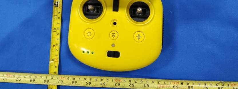
Click to zoom
Application Details
- Equipment Class
- DTS - Digital Transmission System
- Date of Grant
- Jul 20, 2020
- Application Purpose
- Original Equipment
- Date of Application
- Jul 20, 2020
- Equipment Note
- CHASING Underwater Drone Remote
- Frequency Range
- 2412.00000000 - 2462.00000000
- Country
- China
Documents & Files
Document Text
Text extracted from the exhibit documents filed with the FCC. Open a document above to read the original.
Users Manual
User ManualV1.0 DISCLAIMER Thank you for purchasing the CHASING M2 underwater drone. Please read this entire document carefully before using the drone. By using this product, you hereby signify that you have read this disclaimer and all instructions carefully and that you understand and agree to abide by the terms and conditions herein. Chasing accepts no liability for damage, injury, or any legal responsibility incurred directly or indirectly from the use of the CHASING M2 in the following conditions: 01. Damage(s) or injuries incurred when users are drunk, taking drugs, drug anesthesia, dizziness, fatigue, nausea and any other conditions no matter physically or mentally that could impair your ability. 02. Damage(s) or injuries caused by subjective intentional operations. 03. Any mental overcompensation caused by accident. 04. Failure to follow the guidance of the manual to assemble or operate. 05. Malfunctions caused by refit or replacement with non-Chasing accessories and parts, or unauthorized modification, disassembly, or shell opening not in accordance with official instructions. 06. Damage(s) or injuries caused by using third-party products or fake Chasing products. 07. Damage(s) or injuries caused by misoperation or subjective misjudgment. 08. Damage(s) or injuries caused by mechanical failures due to erosion, aging. 09. Damage(s) or injuries caused by operating the unit with a low battery alert. 10. Damage(s) or injuries caused by operating the drone out of maximum safe range and depth. 11. Damage(s) or injuries caused by knowingly operating the product in abnormal conditions (such as the assembly is not completed, or the main components have obvious faults, obvious defect or missing accessories). 12. Damage(s) or injuries caused by operating the drone in a sensitive zone such as a military area or private waters without official permission. 13. Damage or injury caused by using in bad water conditions (such as high winds, or turbid zone). 14. Damage or injury caused by uncontrollable external factors, including severe collision, tidal wave. swallowed by animal. 15. Damage(s) or injuries caused by infringement such as any data, photo or video material recorded by the use of the CHASING M2. 16. Other losses that are not covered by the scope of Chasing's liability. CHASING M2 INSTRUCTION ROV CHASING M2 is a professional underwater ROV/Drone designed for professional users and industrial applications. M2 has 8 Vectored Thrusters layout which allows OMNI movement in all directions. The Maximum speed is 3 Knots, depth is 100 meters (330 FT) and the maximum horizontal radius is 200 meters (660FT). Compatible with sophisticated attachments such as Robot Claw, GoPro camera, external LED lights and laser scaler etc. CHASING M2 offers a built in 4K/ 1080p and 12-megapixel EIS image stabilization camera, 4000 lumen LED lights, removable battery and removable SD memory card. The aluminum alloy compact body (weighs less than 4.5KG / 10lbs) allows single person operation and Quick-Deployment in 3 minutes. The CHASING M2 is your portable, user-friendly and reliable light industrial underwater ROV. 1. Camera 2. LED lights 3. Thruster/ Propeller 4. Micro SD slot 5. Tether socket / Charging socket 6. Sensor 7. Main Cabin 8. Battery Cabin 9. Buckle bracket 10. Peripheral interface 11. Battery pull ring (For battery disassembling) 12. Battery fastener 13. Battery twistlock knob Remote controller The Chasing M2 remote controller had integrated communication and control. It connects directly to the drone via the included tether and connects wirelessly to your mobile phone/tablet via Wi-Fi. It allows the drone to display a live video feed on your phone/tablet, which enables users to control the drone in real-time. The base station's HDMI output can also be used to display a live video feed to a larger screen. 1. Power swi tch: Turns controller on/off 2.Power Indicator: Green (High power), Blue (Medium power), Red (Low power) 3.Signal Indicator: a 2.4G:2.4Ghz Wi-Fi indicator,always on when working b 5G:5Ghz Wi-Fi indicator,always on when working. c ROV(drone):Indicates the communication status between the controller and the drone (Steady light indicates successful connection; Blinking light indicates disconnection.) 4. Unlock:Unlock/Lock,current state of the Thruster will show on the APP 5. Gesture back:ROV can be returned to a horizontal state 6. Led Control:On / off led light (third gear) 7. Safety Buckle:Can be used with a safety rope to prevent the remote control from falling 8. Control Sticks:Used to control the navigation of the ROV. 9. Phone/Tablet Clamp:Used to attach phone/tablet mount to mounting bracket. 10. Clamp Button:Pull apart the two ends and put in the phone/tablet, then press this button to tighten. 11. Robotic Arm Control:Short press to close and stop, long press for one second to open 12. Photo/Video:Short press to take photos, long press to start / end recording video 13. Left Angel Adjustment:Adjust the pitch angle 14. Right Angel Adjustment:Adjust the rollover angle 15. HDMI Socket:1080P HD image real-time output 16. Tether Connection Socket/Charging socket. Note: Do not put the controller in the water to avoid damaging the device, damages caused by water ingress are not covered by the warranty. Handle indicators introduction Battery: Red:10%↓ Red light flashes quickly;10-19% Red light flashes slowly;20-29% Red light always on. Yellow:30-69% Yellow light always on; Green:70-100% Green light always on; Signal Indicator a 2.4G:2.4Ghz Wi-Fi indicator,always on when working. b 5G:5Ghz Wi-Fi indicator,always on when working. c ROV:Indicates the communication status between the controller and the ROV (Steady light indicates successful connection, Blinking light indicates disconnection.) Gesture back Button: The blue light is always on when the ROV is in a non-horizontal position Unlock Button: Locking: No lights Unlocking: Blue light on Led Control Button: Bright light:Blue light alway…
Text truncated - open the document above for the full version.
Cover Letter(s)
QA-FR-170-B Chasing-Innovation Technology Co.,Ltd. Add: ROOM 506 XITA BUILDING, DIGITAL CULTURE INDUSTRY BASE, SHENLAN AVENUE 10128, NANSHAN DISTRICT, Shenzhen, China Tel: 18611822026 Fax: 075526407202 Email: [email protected] FCC Authorization Date: 2020-06-19 FEDERAL COMMUNICATIONS COMMISSION Authorization and Evaluation Division 7435 Oakland Mills Road Columbia, MD 21046 Subject: Agent Authorization To whom it may concern: We , Chasing-Innovation Technology Co.,Ltd. Hereby authorizes Bay Area Compliance Laboratories Corporation to act on its behalf in all matters relating to application for Equipment authorization, including the signing of all documents relating to these matters. All acts carried out by Bay Area Compliance Laboratory Corporation on our behalf shall have the same effect as our own action. We, the undersigned, hereby certify that we are not subject to a denial of federal benefits, that includes FCC benefits, pursuant to Section 5301 of the Anti-Drug Abuse Act of 1988, 21 U.S.C. 862. This authorization is valid until further written notice from the applicant. Sincerely Yours, Client’s signature Printed Name: leon lee Title: manager
Cover Letter(s)
QA-FR-171-A Chasing-Innovation Technology Co.,Ltd. Add: ROOM 506 XITA BUILDING, DIGITAL CULTURE INDUSTRY BASE, SHENLAN AVENUE 10128, NANSHAN DISTRICT, Shenzhen, China Tel: 18611822026 Fax: 075526407202 Email: [email protected] FCC Confidential Authorization Date: 2020-06-19 FEDERAL COMMUNICATIONS COMMISSIONS Authorization and Evaluation Division 7435 Oakland Mills Road Columbia, MD 21046 Subject: Confidentiality Request regarding application for certification of FCC ID: 2AMOD-CHASINGM2 In accordance with Sections 0.457 and 0.459 of the Commission’s Rules, (Chasing-Innovation Technology Co.,Ltd. ) hereby requests long-term confidential treatment of information accompanying this application as outlined below: Block Diagram Schematics Operation Description The above materials contain proprietary and confidential information not customarily released to the public. The public disclosure of these materials provides unjustified benefits to its competitors in the market. Sincerely, Signature: Printed Name: leon lee Title: manager
External Photos
EXHIBIT B - EUT EXTERNAL PHOTOGRAPHS
ID Label/Location Info
Made in China FCC ID:2AMOD-CHASINGM2 IC:22933-CHASINGM2 FCC & IC Label Model: CHASING M2 Input: DC 25.2V 2.9A Label location
Internal Photos
EXHIBIT C - EUT INTERNAL PHOTOGRAPHS RF Chip Antenna Chain 0 Antenna Chain 1
RF Exposure Info
Note: This test report is prepared for the customer shown above and for the device described herein. It may not be duplicated or used in part without prior written consent from Bay Area Compliance Laboratories Corp. (Dongguan). This report must not be used by the customer to claim product certification, approval, or endorsement by A2LA* or any agency of the Federal Government. * This report may contain data that are not covered by the A2LA accreditation and are marked with an asterisk “*”. SAR EVALUATION REPORT For Chasing-Innovation Technology Co.,Ltd. FCC: ROOM 506 XITA BUILDING, DIGITAL CULTURE INDUSTRY BASE, SHENLAN AVENUE 10128, NANSHAN DISTRICT, Shenzhen, China IC: 506 Xita in Digital Cultural Industry Base of Shennan 10128 Nanshan, Nantou Street, Nanshan District, Shenzhen, Guangdong 51800, China FCC ID: 2AMOD-CHASINGM2 IC: 22933-CHASINGM2 Report Type: Original Report Product Type: CHASING underwater drone Report Number: RDG200522003-20 Report Date: 2020-07-11 Reviewed By: Rocky Xiao RF Engineer Prepared By: Bay Area Compliance Laboratories Corp. (Dongguan) No.69 Pulongcun, Puxinhu Industry Area, Tangxia, Dongguan, Guangdong, China Tel: +86-769-86858888 Fax: +86-769-86858891 www.baclcorp.com.cn Bay Area Compliance Laboratories Corp. (Dongguan) Report No.: RDG200522003-20 SAR Evaluation Report 2 of 76 Attestation of Test Results EUT Information EUT Description CHASING underwater drone Tested Model CHASING M2 FCC ID 2AMOD-CHASINGM2 IC 22933-CHASINGM2 Serial Number RDG200522003-SA-S1 Test Date 2020-05-23 MODE Max. SAR Level(s) Reported(W/kg) Limit (W/kg) Handheld Wi-Fi 2.4G 10g Extremity SAR 0.77 4.0 Wi-Fi 5.8G 10g Extremity SAR 0.48 Simultaneous 10g Extremity SAR 1.27 Body Suppored Wi-Fi 2.4G 1g Body SAR 0.46 1.6 Wi-Fi 5.8G 1g Body SAR 0.48 Simultaneous 1g Body SAR 0.95 Applicable Standards FCC 47 CFR part 2.1093 Radiofrequency radiation exposure evaluation: portable devices RSS-102 Issue 5 March 2015 Radio Frequency (RF) Exposure Compliance of Radio communication Apparatus (All Frequenc y Bands). RF Exposure Procedures: TCB Workshop April 2019 IEEE1528:2013 IEEE Recommended Practice for Determining the Peak Spatial-Average Specific Absorption Rate (SAR) in the Human Head from Wireless Communications Devices: Measurement Techniques IEC 62209-1:2016 Measurement procedure for the assessment of specific absorption rate of human exposure to radio frequency fields from hand-held and body-mounted wireless communication devices – Part 1: Devices used next to the ear (Frequency range of 300 MHz to 6 GHz) KDB procedures KDB 447498 D01 General RF Exposure Guidance v06 KDB 865664 D01 SAR Measurement 100 MHz to 6 GHz v01r04 KDB 865664 D02 RF Exposure Reporting v01r02 KDB 248227 D01 802 11 Wi-Fi SAR v02r02 Note: This wireless device has been shown to be capable of compliance for localized specific absorption rate (SAR) for General Population/Uncontrolled Exposure limits specified in FCC 47 CFR part 2.1093/ RSS-102 Issue 5 March 2015 and has been tested in accordance with the measurement procedures specified in IEEE 1528-2013 and RF exposure KDB procedures. The results and statements contained in this report pertain only to the device(s) evaluated. Bay Area Compliance Laboratories Corp. (Dongguan) Report No.: RDG200522003-20 SAR Evaluation Report 3 of 76 TABLE OF CONTENTS DOCUMENT REVISION HISTORY ......................................................................................................................... 4 EUT DESCRIPTION .................................................................................................................................................... 5 TECHNICAL SPECIFICATION ......................................................................................................................................... 5 REFERENCE, STANDARDS, AND GUIDELINES .................................................................................................. 6 SAR LIMITS ................................................................................................................................................................. 7 FACILITIES .................................................................................................................................................................. 8 DESCRIPTION OF TEST SYSTEM .......................................................................................................................... 9 EQUIPMENT LIST AND CALIBRATION ............................................................................................................. 15 EQUIPMENTS LIST & CALIBRATION INFORMATION .................................................................................................... 15 SAR MEASUREMENT SYSTEM VERIFICATION .............................................................................................. 16 LIQUID VERIFICATION ............................................................................................................................................... 16 SYSTEM ACCURACY VERIFICATION ........................................................................................................................... 17 SAR SYSTEM VALIDATION DATA ..................................................................................................................... 18 EUT TEST STRATEGY AND METHODOLOGY ................................................................................................. 20 TEST POSITIONS FOR DEVICE OPERATING NEXT TO A PERSON’S EAR........................................................................ 20 CHEEK/TOUCH POSITION ........................................................................................................................................... 21 EAR/TILT POSITION ................................................................................................................................................... 21 TEST POSITIONS FOR BODY-WORN AND OTHER CONFIGURATIONS ...…
Text truncated - open the document above for the full version.
RF Exposure Info
PROBE CALIBRATION CERTIFICATES DIPOLE CALIBRATION CERTIFICATES
RF Exposure Info
Report No.: RDG200522003-20 Page 1 of 20 Test Plot 1#: WLAN 2.4G Mode B_Close to Body Front_Low_Chain 0 DUT: CHASING underwater drone; Type: CHASING M2; Serial: RDG200522003-SA-S1 Communication System: IEEE 802.11b 2.4GHz; Frequency: 2412 MHz;Duty Cycle: 1:1 Medium parameters used: f = 2412 MHz; σ = 1.763 S/m; ε r = 40.328; ρ = 1000 kg/m 3 Phantom section: Flat Section DASY5 Configuration: Probe: EX3DV4 - SN7329; ConvF(7.6, 7.6, 7.6) @ 2412 MHz; Calibrated: 2019/10/22 Sensor-Surface: 1.4mm (Mechanical Surface Detection) Electronics: DAE4 Sn772; Calibrated: 2019/10/6 Phantom: Twin SAM; Type: Twin SAM V5.0; Serial: TP:1412 Measurement SW: DASY52, Version 52.10 (2); SEMCAD X Version 14.6.12 (7470) Area Scan (101x141x1): Interpolated grid: dx=1.200 mm, dy=1.200 mm Maximum value of SAR (interpolated) = 0.682 W/kg Zoom Scan (5x5x7)/Cube 0: Measurement grid: dx=8mm, dy=8mm, dz=5mm Reference Value = 1.275 V/m; Power Drift = 0.19 dB Peak SAR (extrapolated) = 0.786 W/kg SAR(1 g) = 0.387 W/kg; SAR(10 g) = 0.179 W/kg Maximum value of SAR (measured) = 0.632 W/kg 0 dB = 0.632 W/kg = -1.99 dBW/kg Report No.: RDG200522003-20 Page 2 of 20 Test Plot 2#: WLAN 2.4G Mode B_Close to Body Front_Mid_Chain 0 DUT: CHASING underwater drone; Type: CHASING M2; Serial: RDG200522003-SA-S1 Communication System: IEEE 802.11b 2.4GHz; Frequency: 2437 MHz;Duty Cycle: 1:1 Medium parameters used: f = 2437 MHz; σ = 1.779 S/m; ε r = 40.241; ρ = 1000 kg/m 3 Phantom section: Flat Section DASY5 Configuration: Probe: EX3DV4 - SN7329; ConvF(7.6, 7.6, 7.6) @ 2437 MHz; Calibrated: 2019/10/22 Sensor-Surface: 1.4mm (Mechanical Surface Detection) Electronics: DAE4 Sn772; Calibrated: 2019/10/6 Phantom: Twin SAM; Type: Twin SAM V5.0; Serial: TP:1412 Measurement SW: DASY52, Version 52.10 (2); SEMCAD X Version 14.6.12 (7470) Area Scan (101x141x1): Interpolated grid: dx=1.200 mm, dy=1.200 mm Maximum value of SAR (interpolated) = 0.443 W/kg Zoom Scan (5x5x7)/Cube 0: Measurement grid: dx=8mm, dy=8mm, dz=5mm Reference Value = 1.767 V/m; Power Drift = -0.16 dB Peak SAR (extrapolated) = 0.505 W/kg SAR(1 g) = 0.262 W/kg; SAR(10 g) = 0.137 W/kg Maximum value of SAR (measured) = 0.403 W/kg 0 dB = 0.403 W/kg = -3.95 dBW/kg Report No.: RDG200522003-20 Page 3 of 20 Test Plot 3#: WLAN 2.4G Mode B_Close to Body Front_High_Chain 0 DUT: CHASING underwater drone; Type: CHASING M2; Serial: RDG200522003-SA-S1 Communication System: IEEE 802.11b 2.4GHz; Frequency: 2462 MHz;Duty Cycle: 1:1 Medium parameters used: f = 2462 MHz; σ = 1.812 S/m; ε r = 38.954; ρ = 1000 kg/m 3 Phantom section: Flat Section DASY5 Configuration: Probe: EX3DV4 - SN7329; ConvF(7.6, 7.6, 7.6) @ 2462 MHz; Calibrated: 2019/10/22 Sensor-Surface: 1.4mm (Mechanical Surface Detection) Electronics: DAE4 Sn772; Calibrated: 2019/10/6 Phantom: Twin SAM; Type: Twin SAM V5.0; Serial: TP:1412 Measurement SW: DASY52, Version 52.10 (2); SEMCAD X Version 14.6.12 (7470) Area Scan (101x141x1): Interpolated grid: dx=1.200 mm, dy=1.200 mm Maximum value of SAR (interpolated) = 0.694 W/kg Zoom Scan (5x5x7)/Cube 0: Measurement grid: dx=8mm, dy=8mm, dz=5mm Reference Value = 1.067 V/m; Power Drift = 0.12 dB Peak SAR (extrapolated) = 0.822 W/kg SAR(1 g) = 0.400 W/kg; SAR(10 g) = 0.185 W/kg Maximum value of SAR (measured) = 0.656 W/kg 0 dB = 0.656 W/kg = -1.83 dBW/kg Report No.: RDG200522003-20 Page 4 of 20 Test Plot 4#: WLAN 2.4G Mode B_Close to Body Right_Mid_Chain 0 DUT: CHASING underwater drone; Type: CHASING M2; Serial: RDG200522003-SA-S1 Communication System: IEEE 802.11b 2.4GHz; Frequency: 2437 MHz;Duty Cycle: 1:1 Medium parameters used: f = 2437 MHz; σ = 1.779 S/m; ε r = 40.241; ρ = 1000 kg/m 3 Phantom section: Flat Section DASY5 Configuration: Probe: EX3DV4 - SN7329; ConvF(7.6, 7.6, 7.6) @ 2437 MHz; Calibrated: 2019/10/22 Sensor-Surface: 1.4mm (Mechanical Surface Detection) Electronics: DAE4 Sn772; Calibrated: 2019/10/6 Phantom: Twin SAM; Type: Twin SAM V5.0; Serial: TP:1412 Measurement SW: DASY52, Version 52.10 (2); SEMCAD X Version 14.6.12 (7470) Area Scan (81x141x1): Interpolated grid: dx=1.200 mm, dy=1.200 mm Maximum value of SAR (interpolated) = 0.128 W/kg Zoom Scan (5x5x7)/Cube 0: Measurement grid: dx=8mm, dy=8mm, dz=5mm Reference Value = 2.557 V/m; Power Drift = 0.06 dB Peak SAR (extrapolated) = 0.152 W/kg SAR(1 g) = 0.075 W/kg; SAR(10 g) = 0.040 W/kg Maximum value of SAR (measured) = 0.118 W/kg 0 dB = 0.118 W/kg = -9.28 dBW/kg Report No.: RDG200522003-20 Page 5 of 20 Test Plot 5#: WLAN 2.4G Mode B_Close to Body Front_Mid_Chain 1 DUT: CHASING underwater drone; Type: CHASING M2; Serial: RDG200522003-SA-S1 Communication System: IEEE 802.11b 2.4GHz; Frequency: 2437 MHz;Duty Cycle: 1:1 Medium parameters used: f = 2437 MHz; σ = 1.779 S/m; ε r = 40.241; ρ = 1000 kg/m 3 Phantom section: Flat Section DASY5 Configuration: Probe: EX3DV4 - SN7329; ConvF(7.6, 7.6, 7.6) @ 2437 MHz; Calibrated: 2019/10/22 Sensor-Surface: 1.4mm (Mechanical Surface Detection) Electronics: DAE4 Sn772; Calibrated: 2019/10/6 Phantom: Twin SAM; Type: Twin SAM V5.0; Serial: TP:1412 Measurement SW: DASY52, Version 52.10 (2); SEMCAD X Version 14.6.12 (7470) Area Scan (131x151x1): Interpolated grid: dx=1.200 mm, dy=1.200 mm Maximum value of SAR (interpolated) = 0.139 W/kg Zoom Scan (5x5x7)/Cube 0: Measurement grid: dx=8mm, dy=8mm, dz=5mm Reference Value = 1.763 V/m; Power Drift = 0.08 dB Peak SAR (extrapolated) = 0.157 W/kg SAR(1 g) = 0.082 W/kg; SAR(10 g) = 0.043 W/kg Maximum value of SAR (measured) = 0.129 W/kg 0 dB = 0.129 W/kg = -8.89 dBW/kg Report No.: RDG200522003-20 Page 6 of 20 Test Plot 6#: WLAN 2.4G Mode B_Close to Body Bottom_Low_Chain 1 DUT: CHASING underwater drone; Type: CHASING M2; Serial: RDG200522003-SA-S1 Communication System: IEEE 802.11b 2.4GHz; Frequency: 2412 MHz;Duty Cycle: 1:1 Medium parameters used: f = 2412 MHz; σ = 1.763 S/m; ε r = 40.328; ρ = 1000 kg/m 3 Phantom section: Flat Section DASY5 Configuration: Probe: EX3DV4 - SN7329; ConvF(7.6, 7.6, 7.6) @ 2412 MHz; C…
Text truncated - open the document above for the full version.
RF Exposure Info
Report No.: RDG200522003-20 Page 1 of 4 APPENDIX B EUT TEST POSITION PHOTOS Liquid depth ≥ 15cm Phantom: Twin SAM; Type: Twin SAM V5.0; Serial: TP:1412 Report No.: RDG200522003-20 Page 2 of 4 Body Supported Mode: Close to Body Front Setup Photo (10mm) Close to Body Right Setup Photo (10mm) 10 mm 10 mm Report No.: RDG200522003-20 Page 3 of 4 Close to Body Bottom Setup Photo (10mm) 10mm Report No.: RDG200522003-20 Page 4 of 4 Handheld Mode: Handheld Front Setup Photo (0mm) Handheld Bottom Setup Photo (0mm)
Test Report
FCC PART 15.247 RSS-GEN, ISSUE 5, AMENDMENT 1, MARCH 2019 RSS-247, ISSUE 2, FEBRUARY 2017 TEST REPORT For Chasing-Innovation Technology Co.,Ltd. FCC: ROOM 506 XITA BUILDING, DIGITAL CULTURE INDUSTRY BASE, SHENLAN AVENUE 10128, NANSHAN DISTRICT, Shenzhen, China IC: 506 Xita in Digital Cultural Industry Base of Shennan 10128 Nanshan, Nantou Street, Nanshan District, Shenzhen, Guangdong 51800, China Report Type: Original Report Product Name: CHASING underwater drone Re port Number: RDG200522003-00A Re port Date: 2020-06-23 Reviewed By: Ivan Cao Assistant Mana ger Test Laboratory: Bay Area Compliance Laboratories Corp. (Dongguan) No.69 Pulongcun, Puxinhu Industry Area, Tangxia, Dongguan, Guangdong, China Tel: +86-769-86858888 Fax: +86-769-86858891 www.baclcorp.com.cn FCC ID:2AMOD-CHASINGM2 IC:22933-CHASINGM2 Bay Area Compliance Laboratories Corp. (Dongguan) Report No.: RDG200522003-00A Page 2 of 64 TABLE OF CONTENTS GENERAL INFORMATION ....................................................................................................................................... 4 PRODUCT DESCRIPTION FOR EQUIPMENT UNDER TEST (EUT) ..................................................................................... 4 OBJECTIVE ................................................................................................................................................................... 4 RELATED SUBMITTAL(S)/GRANT(S) ............................................................................................................................. 4 TEST METHODOLOGY .................................................................................................................................................. 4 MEASUREMENT UNCERTAINTY .................................................................................................................................... 5 TEST FACILITY ............................................................................................................................................................. 5 DECLARATIONS ............................................................................................................................................................ 5 SYSTEM TEST CONFIGURATION .......................................................................................................................... 6 DESCRIPTION OF TEST CONFIGURATION ...................................................................................................................... 6 EUT EXERCISE SOFTWARE .......................................................................................................................................... 6 EQUIPMENT MODIFICATIONS ....................................................................................................................................... 9 LOCAL SUPPORT EQUIPMENT LIST AND DETAILS ........................................................................................................ 9 SUPPORT CABLE LIST AND DETAILS ............................................................................................................................ 9 BLOCK DIAGRAM OF TEST SETUP ................................................................................................................................ 9 SUMMARY OF TEST RESULTS ............................................................................................................................. 10 FCC §15.247 (i) & §1.1310 & §2.1093- RF EXPOSURE .......................................................................................... 11 APPLICABLE STANDARD ............................................................................................................................................ 11 FCC §15.203& RSS-GEN CLAUSE 6.8 - ANTENNA REQUIREMENT .............................................................. 12 APPLICABLE STANDARD ............................................................................................................................................ 12 ANTENNA CONNECTOR CONSTRUCTION .................................................................................................................... 13 FCC §15.209, §15.205 & §15.247(d), RSS-247 CLAUSE 5.5, RSS-GEN CLAUSE 8.10 - SPURIOUS EMISSIONS ................................................................................................................................................................. 14 APPLICABLE STANDARD ............................................................................................................................................ 14 EUT SETUP ................................................................................................................................................................ 14 EMI TEST RECEIVER & SPECTRUM ANALYZER SETUP .............................................................................................. 15 TEST PROCEDURE ...................................................................................................................................................... 15 CORRECTED AMPLITUDE & MARGIN CALCULATION ................................................................................................. 15 TEST EQUIPMENT LIST AND DETAILS ......................................................................................................................... 16 TEST DATA ................................................................................................................................................................ 16 FCC §15.247(a) (2), RSS-247 CLAUSE 5.2 a) &RSS-GEN CLAUSE 6.7–6 dB EMISSION BANDWIDTH AND 99% OCCUPIED BANDWIDTH............................................................................................................................... 24 APPLICABLE STANDARD .......................................................................................................................................…
Text truncated - open the document above for the full version.
Test Setup Photos
EXHIBIT D - TEST SETUP PHOTOGRAPHS Radiated Emission Below 1GHz View Radiated Emission Above 1GHz View
Contact Information
Applicant
leon lee
Test Firm
Bay Area Compliance Laboratories Corp.(Dongguan)David Zhang
[email protected]0086 0769 86858888
Technical Specifications
| # | Rule Parts | Frequency Range | Power Output |
|---|---|---|---|
| 1 | 15C | 2.41 GHz - 2.46 GHz | 54.00 mW |
Other Applications from Chasing-Innovation Technology Co.,Ltd.
2AMOD-L1ULTRA
Dec 26, 2025Robotic Pool Cleaner
Equipment Class
NII - Unlicensed National Information Infrastructure TX
2AMOD-WSRC
Nov 20, 2022CHASING WSRC
Equipment Class
DTS - Digital Transmission System
2AMOD-CM2R3
Mar 02, 2021CHASING RC3
Equipment Class
NII - Unlicensed National Information Infrastructure TX