2AMQU-QN-H-220High Performance 802.11ac (2x2) Wave 2 Indoor (Room) Access Point
QUANTUM NETWORKS (SG) PTE.LTD.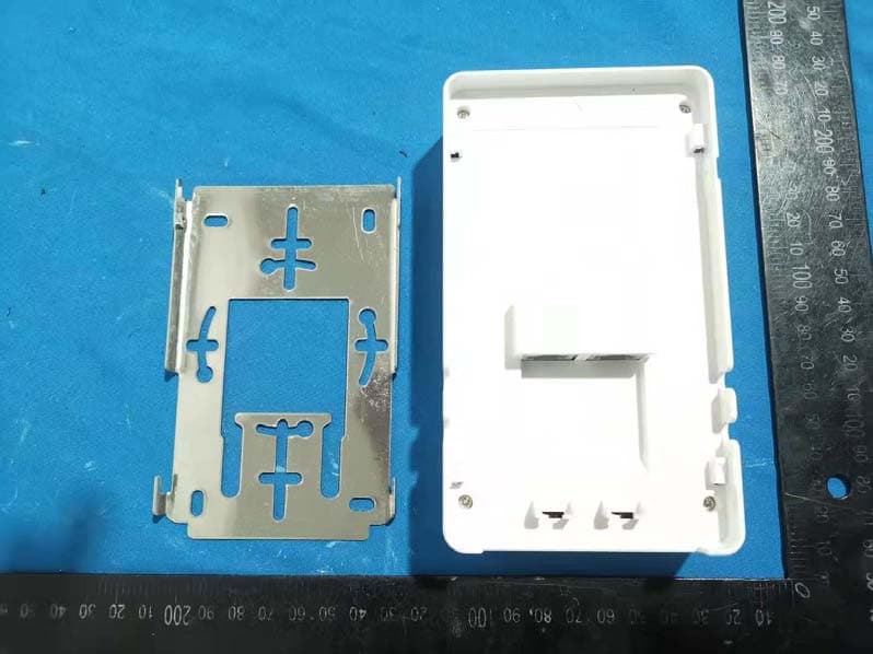
Click to zoom
Application Details
- Equipment Class
- DTS - Digital Transmission System
- Date of Grant
- Feb 26, 2020
- Application Purpose
- Original Equipment
- Date of Application
- Feb 26, 2020
- Equipment Note
- High Performance 802.11ac (2x2) Wave 2 Indoor (Room) Access Point
- Frequency Range
- 2412.00000000 - 2462.00000000
- Country
- Singapore
Documents & Files
Document Text
Text extracted from the exhibit documents filed with the FCC. Open a document above to read the original.
Users Manual
Quick Setup Guide Model: QN-H-220 High Performance 802.11ac (2x2) Wave 2 Indoor(Room) Access Point Copyright Information Copyright & trademark specifications are subject to change without prior notice. Copyright © 2018 Quantum Networks TM (SG) Pte. Ltd. All Rights Reserved. Quantum Networks TM & the logo are trademarks of Quantum Networks TM (SG) Pte. Ltd. Other brands or products mentioned may be trademarks or registered trademarks of their respective owners. Mentioned contents of this document can’t be used, translated or transmitted in any form or by any means without taking prior written permission from Quantum Networks TM (SG) Pte. Ltd.. Contents Before You Begin ....................................................................................................................... 4 Package Contents ...................................................................................................................... 4 Set up Requirements ................................................................................................................. 4 Connect AP ................................................................................................................................ 4 Step 1- Access Point Initial Configuration................................................................................. 5 Step 2- Access Point quick configuration in Standalone mode ............................................... 6 Step 3- Access Point quick configuration in Cloud Controller mode ....................................... 6 Step 4 – Account setup on Quantum Rudder (Quantum Networks TM Cloud Controller) ........ 7 Step 5 – How to Factory Reset AP ............................................................................................ 8 Access Point Default login detail .............................................................................................. 8 FCC Statement: ......................................................................................................................... 9 This Quick Setup Guide provides step-by-step instructions on how to set up Quantum Networks TM Access Point. After completing the steps described in this Guide, you will be able to install the Access Point (AP) on site and provide wireless network access to users. Before You Begin Your Quantum Networks TM Access Point can be managed by “QUANTUM RUDDER “ (Quantum Networks TM Cloud Controller) or can work in “Standalone” Mode. To manage Access Point from “QUANTUM RUDDER”, please follow step 4 first then step 1 ahead. For Standalone mode, continue with step 1 ahead. Package Contents • Quantum Networks TM Access Point • Access Point Quick Setup Guide • Mounting Bracket • Screws Set Set up Requirements A Desktop / Laptop / Mobile device. Ethernet cable. Internet connectivity. AC adapter (Purchase separately) or 802.3af / 802.3at compliant PoE switch (power over ethernet) or PoE injector. Connect AP After unpacking AP from package, connect it to Internet source. Plug in Ethernet cable to WAN port of AP. Power on AP by connecting AC adopter or 802.3af / 802.3at compliant PoE switch. Note : Access point must have internet access during initial setup for the first time for activation of the device, warranty and support. Step 1- Access Point Initial Configuration Provide internet access to WAN port of the Access Point. Access point default SSID QN_XX: XX will broadcast. (Where XX: XX are last four digits of Access Point MAC Address). Connect QN_XX: XX SSID and browse access point default IP 169.254.1.1. Below screen appears. Figure 1 Click on Start Configuration (Figure1). Do IPv4 setup by selecting required option DHCP, Static or PPPoE and click on Next. (Figure2). On successful IP setup, Management Mode setup screen would (Figure3) appear. Set user name and password of your choice. Figure 2 Figure 3 Quantum Networks TM Access Point can be configured in two modes. Standalone Mode (Independent management of each Access point) (please go to step 2) Cloud Controller mode (Centralized management of Access Points using Quantum Network cloud) (please go to step 3) Step 2- Access Point quick configuration in Standalone mode Select Management Mode as Standalone and click on Next. Admin can select AP operation mode as Bridge or Router. o Bridge (In this mode, device connects to a wired or wireless router via an Ethernet cable) o Router (Gateway) (In this mode, device connects to the internet directly and shares internet access to multiple wired and wireless devices. o For Operation Mode - Bridge, select option and follow below procedure. Configure WLAN (SSID) parameters and click on Next. Configuration Summary screen will appear. Click on Reconfigure if any changes required or click on Finish to complete the quick configuration. o For Operation Mode - Router, select option and follow below procedure. Configure WLAN (SSID) and Local subnet parameters and click on Next. Configuration Summary screen will appear. Click on Reconfigure if any changes required or click on Finish to complete the quick configuration. Step 3- Access Point quick configuration in Cloud Controller mode Select Management Mode as Cloud Controller. Enter Cloud controller account credentials (If yet you have not created account on QN cloud, please refer Step 4). Click on Next. Admin can select AP operation mode as Bridge or Router. Select mode and click on Next. o For Operation Mode - Bridge, select option and follow below procedure. By selecting option Bridge, Configuration Summary screen will appear. Click on Reconfigure if any changes required or click on Finish to complete the quick configuration. o For Operation Mode - Router, select option and follow below procedure. Configure WLAN (SSID) and Local subnet parameters and click on Next. Configuration Summary screen will appear. Click on Reconfigure if any changes required or click on Finish to complete the quick configurati…
Text truncated - open the document above for the full version.
External Photos
EXHIBIT B - EUT EXTERNAL PHOTOGRAPHS PORT PORT PORT
ID Label/Location Info
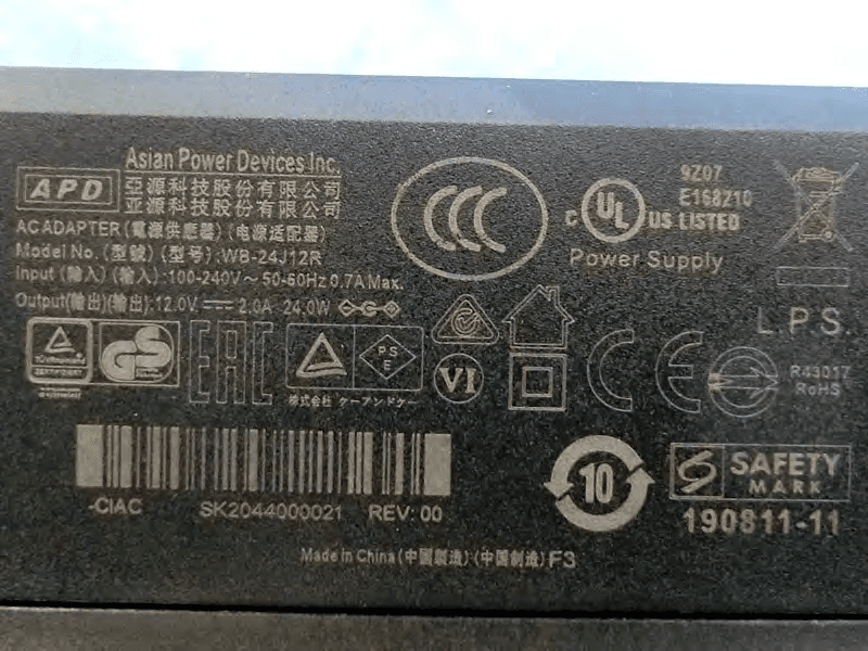
label and locatiom
Internal Photos
EXHIBIT C - EUT INTERNAL PHOTOGRAPHS Uncover 5G Chain 0 5G Chain 1 2.4G Chain 0 2.4G Chain 1 Chip Chip
RF Exposure Info
Bay Area Compliance Laboratories Corp. (Dongguan) Report No.: RDG191126003-00A Page 12 of 68 FCC §15.247 (i) & §1.1310 & §2.1091- MAXIMUM PERMISSIBLE EXPOSURE (MPE) Applicable Standard According to subpart 15.247(i)and subpart §1.1310, systems operating under the provisions of this section shall be operated in a manner that ensures that the public is not exposed to radio frequency energy level in excess of the Commission’s guidelines. Limits for Maximum Permissible Exposure (MPE) (§1.1310, §2.1091) (B) Limits for General Population/Uncontrolled Exposure Frequency Range (MHz) Electric Field Strength (V/m) Magnetic Field Strength (A/m) Power Density (mW/cm 2 ) Averaging Time (minutes) 0.3–1.34 614 1.63 *(100) 30 1.34–30 824/f 2.19/f *(180/f²) 30 30–300 27.5 0.073 0.2 30 300–1500 / / f/1500 30 1500–100,000 / / 1.0 30 f = frequency in MHz; * = Plane-wave equivalent power density; According to §1.1310 and §2.1091 RF exposure is calculated. Calculation formula: Prediction of power density at the distance of the applicable MPE limit S = PG/4R² = power density (in appropriate units, e.g. mW/cm 2 ); P = power input to the antenna (in appropriate units, e.g., mW); G = power gain of the antenna in the direction of interest relative to an isotropic radiator, the power gain factor, is normally numeric gain; R = distance to the center of radiation of the antenna (appropriate units, e.g., cm); For simultaneously transmit system, the calculated power density should comply with: Bay Area Compliance Laboratories Corp. (Dongguan) Report No.: RDG191126003-00A Page 13 of 68 Calculated Data: Mode Frequency (MHz) Antenna Gain Conducted output power including Tune- up Tolerance Evaluation Distance (cm) Power Density (mW/cm 2 ) MPE Limit (mW/cm 2 ) (dBi) (numeric)(dBm)(mW) WLAN 2412-24623 2.00 25316.23 20.00 0.13 1.0 WLAN 5150-52503 2.00 23199.53 20.00 0.08 1.0 WLAN 5725-58503 2.00 22158.49 20.00 0.06 1.0 The WLAN 2.4G and 5G can transmit simultaneously: =S 2.4 /S limit-2.4 + S 5 /S limit-5 =0.13/1+0.08/1 =0.21 < 1.0 Result: The device meet FCC MPE at 20 cm distance
Test Report
FCC PART 15.247 TEST REPORT For QUANTUM NETWORKS (SG) PTE.LTD. 8 UBI ROAD 2 #08-10 ZERVEX SINGAPORE(408538),SINGAPORE,Singapore Report Type: Original Report Product Name: High Performance 802.11ac (2x2) Wave 2 Indoor(Room) Access Point Re port Number: RDG191126003-00A Re port Date: 2020-01-19 Reviewed By: Ivan Cao Assistant manager Test Laboratory: Bay Area Compliance Laboratories Corp. (Dongguan) No.69 Pulongcun, Puxinhu Industry Area, Tangxia, Dongguan, Guangdong, China Tel: +86-769-86858888 Fax: +86-769-86858891 www.baclcorp.com.cn FCC ID: 2AMQU-QN-H-220 Bay Area Compliance Laboratories Corp. (Dongguan) Report No.: RDG191126003-00A Page 2 of 68 TABLE OF CONTENTS GENERAL INFORMATION ....................................................................................................................................... 4 PRODUCT DESCRIPTION FOR EQUIPMENT UNDER TEST (EUT) ..................................................................................... 4 OBJECTIVE ................................................................................................................................................................... 4 RELATED SUBMITTAL(S)/GRANT(S) ............................................................................................................................. 4 TEST METHODOLOGY .................................................................................................................................................. 4 MEASUREMENT UNCERTAINTY .................................................................................................................................... 5 TEST FACILITY ............................................................................................................................................................. 5 DECLARATIONS ............................................................................................................................................................ 5 SYSTEM TEST CONFIGURATION .......................................................................................................................... 6 DESCRIPTION OF TEST CONFIGURATION ...................................................................................................................... 6 EUT EXERCISE SOFTWARE .......................................................................................................................................... 6 EQUIPMENT MODIFICATIONS ....................................................................................................................................... 9 LOCAL SUPPORT EQUIPMENT LIST AND DETAILS ........................................................................................................ 9 SUPPORT CABLE LIST AND DETAILS ............................................................................................................................ 9 CONFIGURATION OF TEST SETUP ............................................................................................................................... 10 SUMMARY OF TEST RESULTS ............................................................................................................................. 11 FCC §15.247 (i) & §1.1310 & §2.1091- MAXIMUM PERMISSIBLE EXPOSURE (MPE) ....................................... 12 APPLICABLE STANDARD ............................................................................................................................................ 12 FCC §15.203 - ANTENNA REQUIREMENT ........................................................................................................... 14 APPLICABLE STANDARD ............................................................................................................................................ 14 ANTENNA CONNECTOR CONSTRUCTION .................................................................................................................... 14 FCC §15.207 (a) – AC LINE CONDUCTED EMISSIONS ..................................................................................... 15 APPLICABLE STANDARD ............................................................................................................................................ 15 EUT SETUP ................................................................................................................................................................ 15 EMI TEST RECEIVER SETUP ....................................................................................................................................... 15 TEST PROCEDURE ...................................................................................................................................................... 16 CORRECTED AMPLITUDE & MARGIN CALCULATION ................................................................................................. 16 TEST EQUIPMENT LIST AND DETAILS ......................................................................................................................... 16 TEST DATA ................................................................................................................................................................ 16 FCC §15.209, §15.205 & §15.247(d) - SPURIOUS EMISSIONS ............................................................................. 21 APPLICABLE STANDARD ............................................................................................................................................ 21 EUT SETUP ................................................................................................................................................................ 21 EMI TEST RECEIVER & SPECTRUM ANALYZER SETUP .............................................................................................. 22 TEST PROCEDURE ...............................................................................................................................…
Text truncated - open the document above for the full version.
Test Setup Photos
EXHIBIT D - TEST SETUP PHOTOGRAPHS Conducted Emissions Front View-AC/DC Adapter Conducted Emissions Side View- AC/DC Adapter Conducted Emissions Front View- PoE Adapter Conducted Emissions Side View- PoE Adapter Radiated Emission Below 1GHz View Radiated Emission Above 1GHz View
Contact Information
Applicant
Deepak Chandrayan(Administrative Officer)
Test Firm
Bay Area Compliance Laboratories Corp.(Dongguan)David Zhang
[email protected]0086 0769 86858888
Technical Specifications
| # | Rule Parts | Frequency Range | Power Output |
|---|---|---|---|
| 1 | 15C | 2.41 GHz - 2.46 GHz | 265.00 mW |
Other Applications from QUANTUM NETWORKS (SG) PTE.LTD.
2AMQU-QN-I-270
Nov 24, 2021Dual-Band Wi-Fi 6 indoor Access Point (802.11 ax 2X2)
Equipment Class
DTS - Digital Transmission System